Arduino: Precision Lib for Stepper Motor
by Fernando Koyanagi in Circuits > Arduino
4605 Views, 3 Favorites, 0 Comments
Arduino: Precision Lib for Stepper Motor


Today, I will show you a library for a full step motor driver with limit switches, and engine movement with acceleration and micro step. This Lib, which works on both the Arduino Uno and the Arduino Mega, allows you to move the engines based not only on the number of steps, but also on millimeters. And it’s pretty accurate as well.
An important feature of this library is that it allows you to build your own CNC machine, which is not necessarily just the X, Y, but also a section switch, for example, because it is not a ready GRBL, but rather the programming that allows you to make the ideal machine for you.
However, the following statement is an important detail! This video is only for those who are already accustomed to programming. If you aren’t familiar with Arduino programming, you should first watch other more introductory videos on my channel. This is because I am discussing an advanced subject in this specific video, and explaining in further detail the Lib used in the video: Step Motor with Acceleration and End of Stroke.
StepDriver Library
This library covers the three most common driver types on the market: A4988, DRV8825, and TB6600. It configures the pins of the drivers, allowing them to perform the reset and placement into Sleep mode, as well as activate and deactivate the motor outputs acting on the Enable pin. It also sets the inputs of the micro-step pins of the driver, and limits switches and their activation level (high or low). It also has motor movement code with continuous acceleration in mm / s², maximum speed in mm / s, and minimum speed in mm / s.
For those who watched parts 1 and 2 of the video Step Motor with Acceleration and End of Stroke, download this new library available today, because I made some changes in that first file to facilitate its use.
Global Variables

I show exactly what each of the global variables is for.
Functions - Setting the Driver Pins
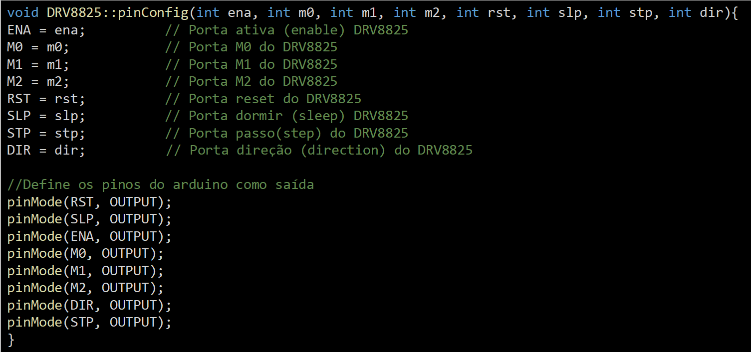
Here, I describe some methods.
I set the Pinout setting and the Arduino pins as output.
Functions - Basic Functions of the Driver
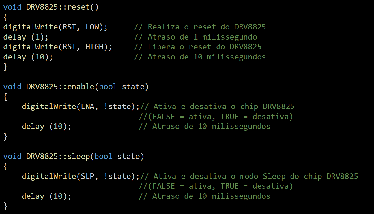
In this part, we work with the configuration of the driver and its basic functions.
Functions - Motor Step Setting
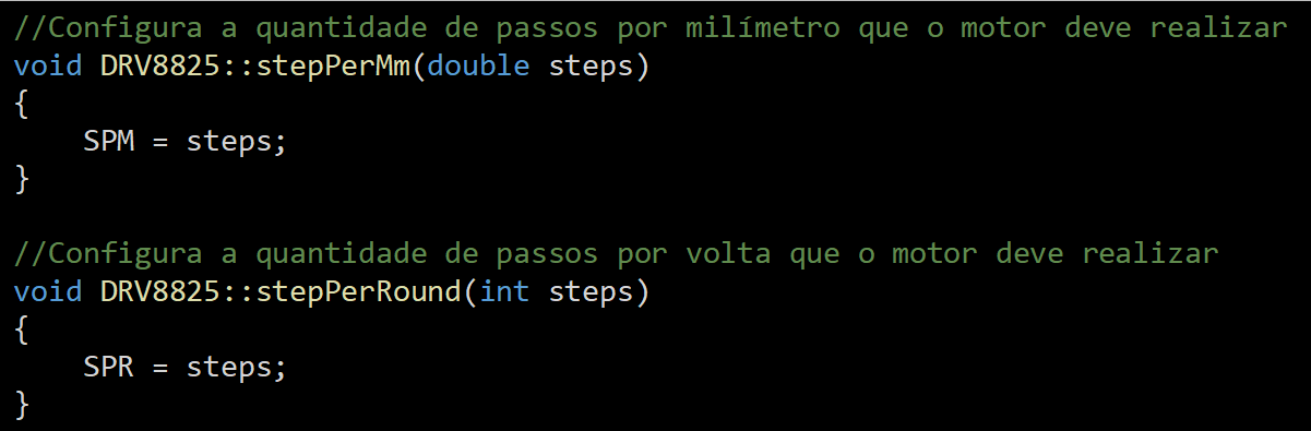
In this step of the code, we configure the amount of steps per millimeter that the motor must execute.
Functions - Setting the Motor Step Mode
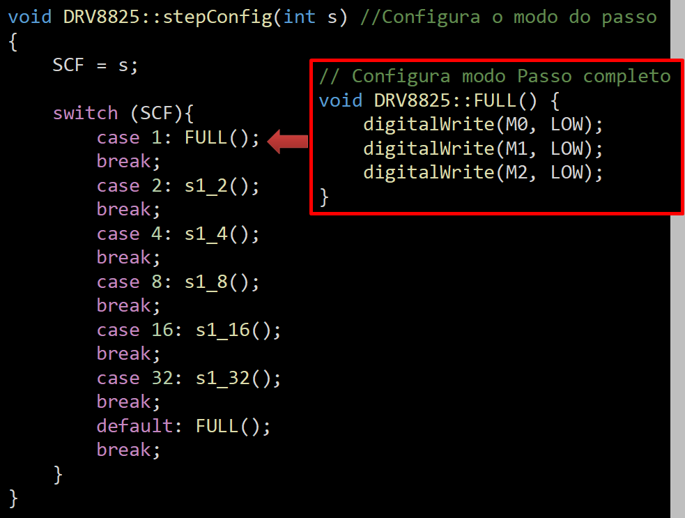
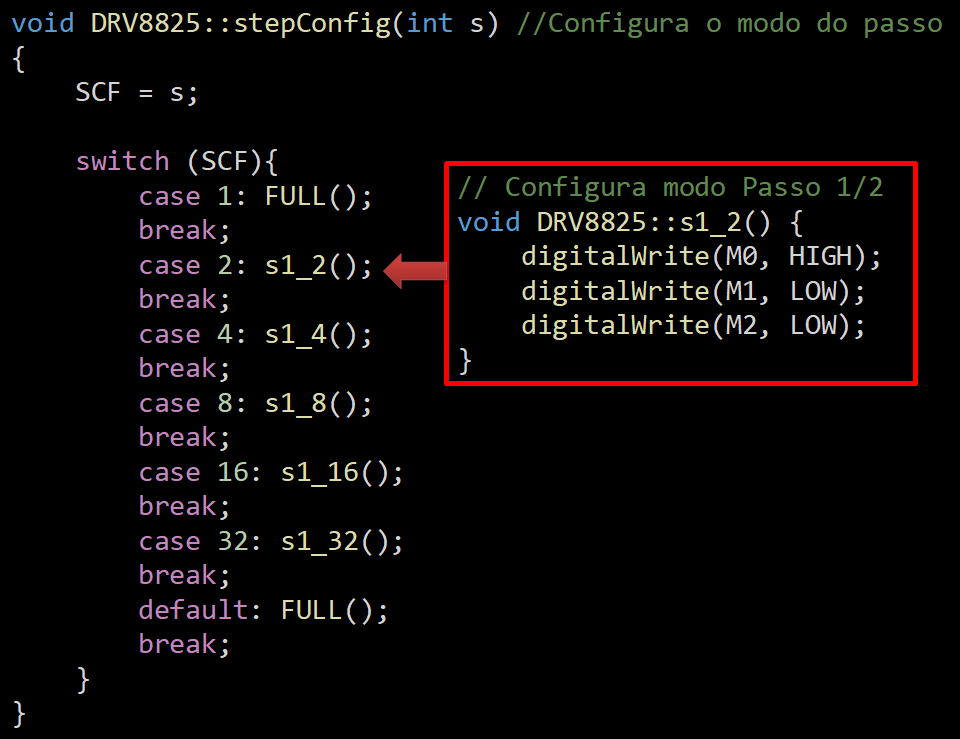


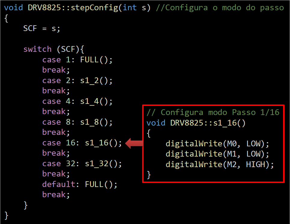

This table shows the settings for the motor step mode. Here are some examples.
Functions - Setting the Limit Switches

Here, I have to read the whole and boolean values. It is necessary to set whether the active key is up or down, while setting the maximum and minimum limit endpin.
Functions - Reading of Limit Switches

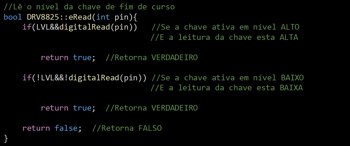

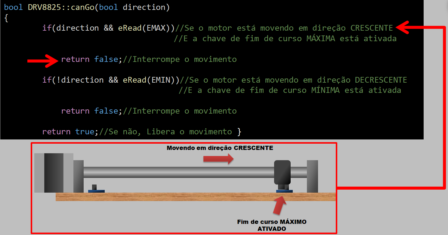
This part is different from the one in the Lib that I made available last week. Why did I change it? Well, I created eRead to replace some others. Here, the eRead will read the LVL, the digitalRead (pin), and will return TRUE. All this needs to be performed at high. The following work with the active key will be at the low level. I'll use it here to show you the "Truth" table.
In the image of code, I placed a diagram that will help in the understanding that, in this part of the source code, I am moving towards Ascending and have not yet hit the end of course key.
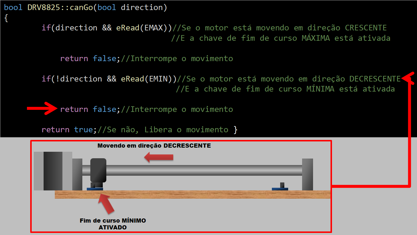
Now, in this image os code bool DRV8825, I show the engine still moving in the growing direction. However, the maximum limit switch activated. The mechanism, then, must stop the movement.
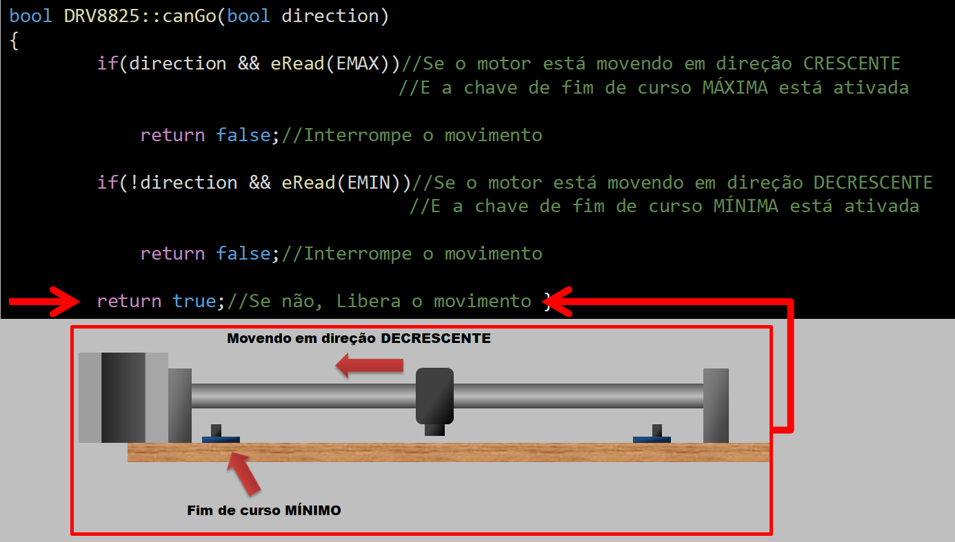
For last, I show the same movement, but in the opposite direction.
Here, you already have the end of course switch activated.
Functions - Motion Setup

The main utility of the motionConfig method is to convert millimeter per second (a measurement used in CNC machines) to steps, in order to meet the controller of a stepper motor. It is in this part, therefore, that I instantiate the variables to understand the steps and not the millimeters.
Functions - Movement Function

In this step, we treat the command that moves a step in the desired direction in a period in microseconds. We also set the driver's direction pin, delay time, and direction of limit switches.
Functions - Movement Function - Variables
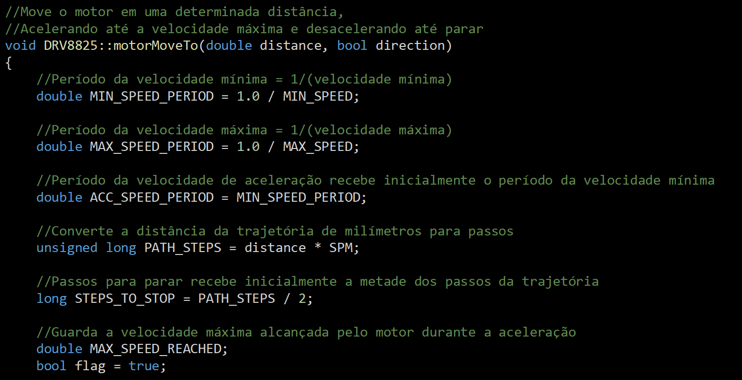
In this part, we configure all the variables that involve periods of maximum and minimum speed, distance of trajectory, and steps necessary to interrupt the trajectory, among others.
Functions - Movement Function - Acceleration


Here, I present some details about how we arrived at the acceleration data, which was calculated through Torricelli's equation, since this takes into account the spaces to work the acceleration and not the time. But, it is important here to understand that this whole equation is only about just one line of code.
We identified a trapeze in the image above, because the initial RPMs are bad for most stepper motors. The same thing happens with the deceleration. Because of this, we visualize a trapezoid in the period between acceleration and deceleration.
Functions - Motion Function - Continuous Speed

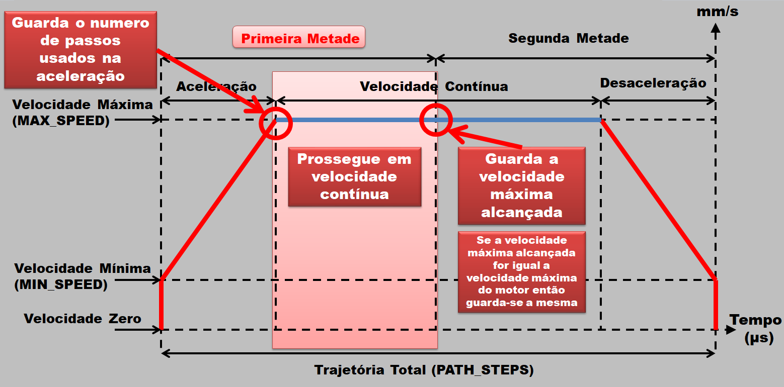
Here we keep the number of steps used in the acceleration, we continue in continuous speed, and keep with the maximum speed, which can be seen in the image below.
Functions - Movement Function - Deceleration
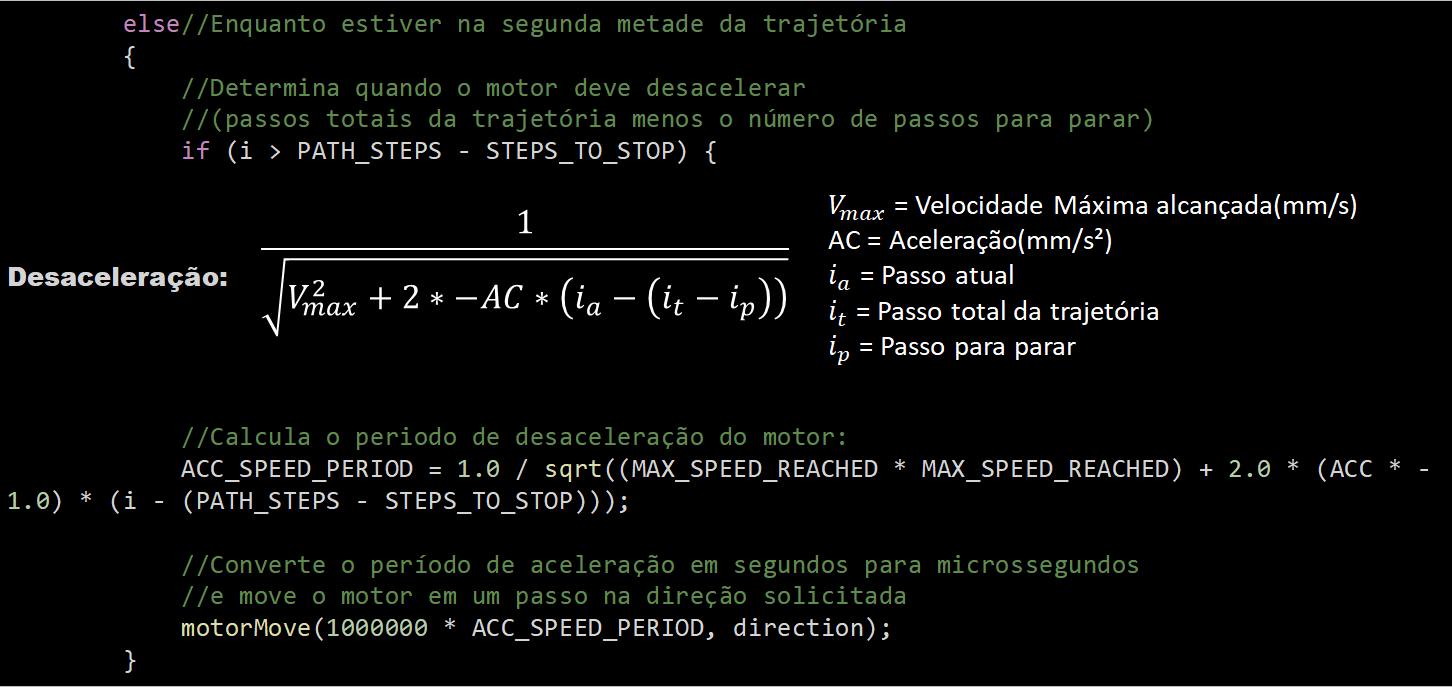
Here we have another equation, this time with a negative acceleration value. It is also displayed in a line of code, which represents, in the image below, the rectangle labeled Deceleration.
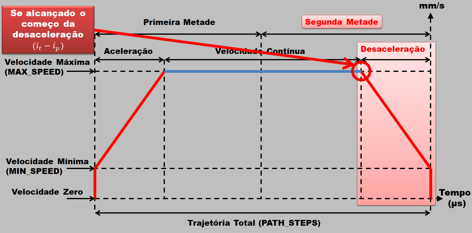
Functions - Motion Function - Continuous Speed
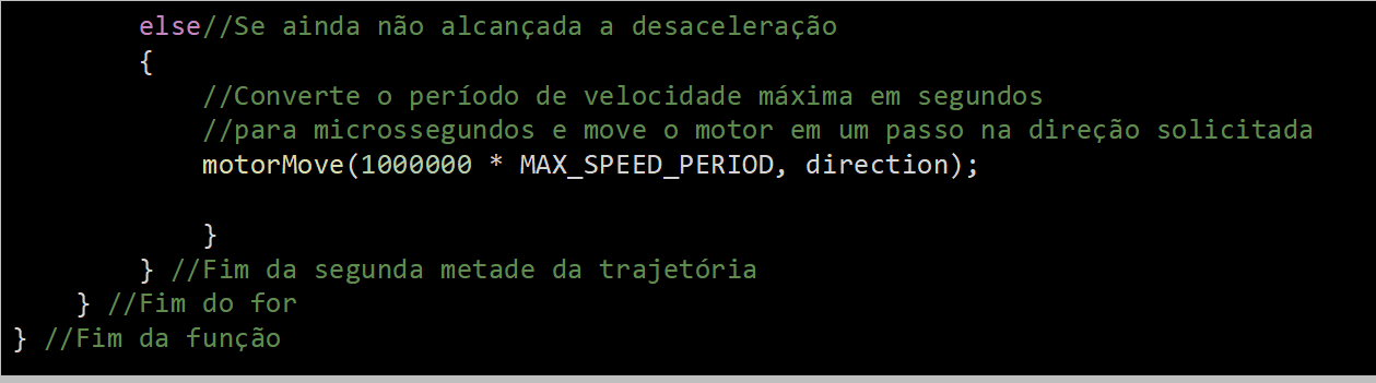
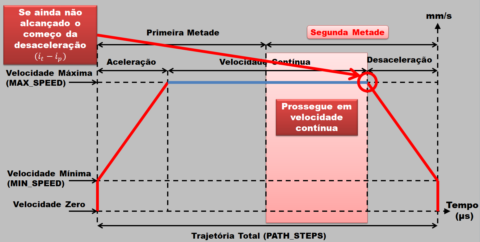
We return to continuous speed to work the second half of the trajectory, as seen below.
Functions - Move Function - Move Turns

In this part, we move the engine in a certain number of turns in the desired direction, converting the number of turns in millimeters. Finally, we move the motor in the requested direction.
Motion Chart - Position Velocity

In this graph, I have data that was extracted from the equation that we used in the part of Acceleration. I took the values and played on the Arduino serial, and I went from this to Excel, which resulted in this table. This table shows the progress of the step.
Motion Chart - Position Vs. Position

Here, we take the position, in steps, and the velocity and convert it to period, in microsecond. We note in this step that the period is inversely proportional to velocity.
Motion Chart - Velocity Vs. Moment

Finally, we have the velocity as a function of the instant, and because of this, we have a straight line, since it is the velocity as a function of time.