Arduino and Thumbwheel Switches
by pmdwayhk in Circuits > Arduino
6582 Views, 5 Favorites, 0 Comments
Arduino and Thumbwheel Switches

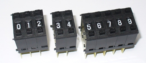
In this article we examine the use of push-wheel/thumbwheel switches with our Arduino systems. Here are some examples sourced from PMD Way.

For the uninitiated, each switch is one vertical segment and they can be connected together to form various sizes. You can use the buttons to select from digits zero through to nine. There are alternatives available that have a wheel you can move with your thumb instead of the increase/decrease buttons.
Before the days of fancy user interfaces these switches were quite popular methods for setting numerical data entry. However they are still available today, so let’s see how they work and how we can use them. The switch’s value is made available via binary-coded decimal or straight decimal. Consider the rear of the switch in BCD form.

We have common on the left, then contacts for 1, 2, 4 and 8. If you apply a small voltage (say 5V) to common, the value of the switch can be measured by adding the values of the contacts that are in the HIGH state. For example, if you select 3 – contacts 1 and 2 will be at the voltage at common. The values between zero and nine can be represented as such in the table.
.jpg)
By now you should realise that it would be easy to read the value of a switch – and you’re right, it is. We can connect 5V to the common, the outputs to digital input pins of our Arduino boards, then use digitalRead() to determine the value of each output. In the sketch we use some basic mathematics to convert the BCD value to a decimal number. So let’s do that now.
From a hardware perspective, we need to take into account one more thing – the push-wheel switch behaves electrically like four normally-open push buttons. This means we need to use pull-down resistors in order to have a clear difference between high and low states. So the schematic for one switch is as shown above.
Now it is a simple matter to connect the outputs labelled 1, 2, 4, and 8 to (for example) digital pins 8, 9, 10 and 11. Connect 5V to the switch ‘C’ point, and GND to … GND. Next, we need to have a sketch that can read the inputs and convert the BCD output to decimal. Consider the following sketch:
/*
 Uses SAA1064 numerical display shield http://www.gravitech.us/7segmentshield.html
 Uses serial monitor if you don't have the SAA1064 shield
*/
#include "Wire.h"
#define q1 8
#define q2 9
#define q4 10
#define q8 11
void setup()
{
 Serial.begin(9600);
 Wire.begin(); // join i2c bus (address optional for master)
 delay(500);
 pinMode(q1, INPUT); // thumbwheel '1'
 pinMode(q2, INPUT); // thumbwheel '2'
 pinMode(q4, INPUT); // thumbwheel '4'
 pinMode(q8, INPUT); // thumbwheel '8'
}
void dispSAA1064(int Count)
// sends integer 'Count' to Gravitech SAA1064 shield
{
 const int lookup[10] = {
 0x3F,0x06,0x5B,0x4F,0x66,0x6D,0x7D,0x07,0x7F,0x6F };
 int Thousands, Hundreds, Tens, Base;
 Wire.beginTransmission(0x38);
 Wire.write(0);
 Wire.write(B01000111);
 Wire.endTransmission();
 Wire.beginTransmission(0x38);
 Wire.write(1);
 Thousands = Count/1000;
 Hundreds = (Count-(Thousands*1000))/100;
 Tens = (Count-((Thousands*1000)+(Hundreds*100)))/10;
 Base = Count-((Thousands*1000)+(Hundreds*100)+(Tens*10));
 Wire.write(lookup[Base]);
 Wire.write(lookup[Tens]);
 Wire.write(lookup[Hundreds]);
 Wire.write(lookup[Thousands]);
 Wire.endTransmission();
 delay(10);
}
int readSwitch()
{
 int total=0;
 if (digitalRead(q1)==HIGH) { total+=1; }
 if (digitalRead(q2)==HIGH) { total+=2; }
 if (digitalRead(q4)==HIGH) { total+=4; }
 if (digitalRead(q8)==HIGH) { total+=8; }
 return total;
}
void loop()
{
 dispSAA1064(readSwitch()); // sends switch value to display shield
 Serial.println(readSwitch()); // sends switch value to serial monitor box
}
The function readSwitch() is the key. It calculates the value of the switch by adding the numerical representation of each switch output and returns the total as its result. For this example we used a numerical display shield that is controlled by the NXP SAA1064.

The function readSwitch() is the key. It calculates the value of the switch by adding the numerical representation of each switch output and returns the total as its result. For this example we used a numerical display shield that is controlled by the NXP SAA1064.
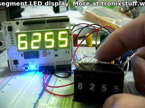
If you don’t have one, that’s ok – the results are also sent to the serial monitor. Now, let’s see it in action in the video.
Ok it doesn’t look like much, but if you need numerical entry it saves a lot of physical space and offers a precise method of entry.
So there you have it. Would you actually use these in a project? For one digit – yes. For four? Probably not – perhaps it would be easier to use a 12-digit keypad. There’s an idea…
Multiple Switches

Now we will examine how to read four digits – and not waste all those digital pins in the process. Instead, we will use the Microchip MCP23017 16-bit port expander IC that communicates via the I2C bus. It has sixteen digital input/output pins that we can use to read the status of each switch.
Before moving forward, please note that some assumed knowledge is required for this article – the I2C bus (parts one and two) and the MCP23017. We first will describe the hardware connections, and then the Arduino sketch. Recall the schematic used for the single switch example.
When the switch was directly connected to the Arduino, we read the status of each pin to determine the value of the switch. We will do this again, on a larger scale using the MCP23017. Consider the pinout diagram:

We have 16 pins, which allows four switches to be connected. The commons for each switch still connect to 5V, and each switch contact still has a 10k pull-down resistor to GND. Then we connect the 1,2,4,8 pins of digit one to GPBA0~3; digit two’s 1,2,4,8 to GPA4~7; digit three’s 1,2,4,8 to GPB0~3 and digit four’s 1,2,4,8 to GPB4~7.
Now how do we read the switches? All those wires may cause you to think it is difficult, but the sketch is quite simple. When we read the value of GPBA and B, one byte is returned for each bank, with the most-significant bit first. Each four bits will match the setting of the switch connected to the matching I/O pins. For example, if we request the data for both IO banks and the switches are set to 1 2 3 4 – bank A will return 0010 0001 and bank B will return 0100 0011.
We use some bitshift operations to separate each four bits into a separate variable – which leaves us with the value of each digit. For example, to separate the value of switch four, we shift the bits from bank B >> 4. This pushes the value of switch three out, and the blank bits on the left become zero.
To separate the value for switch three, we use a compound bitwise & – which leaves the value of switch three. The image shows a breakdown of the binary switch values – it shows the raw GPIOA and B byte values, then each digit’s binary value, and decimal value.

So let’s see the demonstration sketch :
/*
 Example 40a - Read four pushwheel BCD switches via MCP23017, display on SAA1064/4-digit 7-segment LED display
 */
// MCP23017 pins 15~17 to GND, I2C bus address is 0x20
// SAA1064 I2C bus address 0x38
#include "Wire.h"
// for LED digit definitions
int digits[16]={
  63, 6, 91, 79, 102, 109, 125,7, 127, 111, 119, 124, 57, 94, 121, 113};
byte GPIOA, GPIOB, dig1, dig2, dig3, dig4;
void initSAA1064()
{
  //setup 0x38
  Wire.beginTransmission(0x38);
  Wire.write(0);
  Wire.write(B01000111); // 12mA output, no digit blanking
  Wire.endTransmission();
}
void setup()
{
  Serial.begin(9600);
  Wire.begin(); // start up I2C bus
  initSAA1064();
}
void loop()
{
  // read the inputs of bank A
  Wire.beginTransmission(0x20);
  Wire.write(0x12);
  Wire.endTransmission();
  Wire.requestFrom(0x20, 1);
  GPIOA=Wire.read(); // this byte contains the switch data for digits 1 and 2
  // read the inputs of bank B
  Wire.beginTransmission(0x20);
  Wire.write(0x13);
  Wire.endTransmission();
  Wire.requestFrom(0x20, 1);
  GPIOB=Wire.read(); // this byte contains the switch data for digits 3 and 4
  // extract value for each switch
  // dig1 LHS, dig4 RHS
  dig4=GPIOB >> 4;
  dig3=GPIOB & B00001111;
  dig2=GPIOA >> 4;
  dig1=GPIOA & B00001111;
  // send all GPIO and individual switch data to serial monitor
  // for debug and interest's sake
  Serial.print("GPIOA = ");
  Serial.println(GPIOA, BIN);
  Serial.print("GPIOB = ");
  Serial.println(GPIOB, BIN);
  Serial.println();
  Serial.print("digit 1 = ");
  Serial.println(dig1, BIN);
  Serial.print("digit 2 = ");
  Serial.println(dig2, BIN);
  Serial.print("digit 3 = ");
  Serial.println(dig3, BIN);
  Serial.print("digit 4 = ");
  Serial.println(dig4, BIN);
  Serial.println();
  Serial.print("digit 1 = ");
  Serial.println(dig1, DEC);
  Serial.print("digit 2 = ");
  Serial.println(dig2, DEC);
  Serial.print("digit 3 = ");
  Serial.println(dig3, DEC);
  Serial.print("digit 4 = ");
  Serial.println(dig4, DEC);
  Serial.println();
  // send switch value to LED display via SAA1064
  Wire.beginTransmission(0x38);
  Wire.write(1);
  Wire.write(digits[dig4]);
  Wire.write(digits[dig3]);
  Wire.write(digits[dig2]);
  Wire.write(digits[dig1]);
  Wire.endTransmission();
  delay(10);
  delay(1000);
}
And for the non-believers … a video demonstration.
So there you have it. Four digits instead of one, and over the I2C bus conserving Arduino digital I/O pins. Using eight MCP23017s you could read 32 digits at once. Have fun with doing that!
You can order both BCD and decimal switches in various sizes from PMD Way, with free delivery worldwide.
This post brought to you by pmdway.com – everything for makers and electronics enthusiasts, with free delivery worldwide.