Art Deco Weather Forecast Display
by educ8s in Circuits > Electronics
23686 Views, 314 Favorites, 0 Comments
Art Deco Weather Forecast Display


Hello Friends,
in this Instructable we are going to see hot to build this Weather Forecast Display. It uses a Wemos D1 mini board along with a 1.8” Color TFT screen to display the weather forecast. I also designed and 3d printed an enclosure for this project using wood filament! I got the inspiration for this Art Deco style enclosure from an old radio. I wanted a design for the Weather Station that would be unique and somehow artistic, I was bored of the square enclosures without any character. I wanted something to make me feel good when looking at it.
The project connects to the internet and retrieves the weather forecast for my location and displays it on the screen. The project only displays the weather icon, the temperature and the time of the prediction because I wanted a minimal look for this project. Of course you can easily add more information if you wish. Now let’s see how to build this project.
Get All the Parts

The parts needed in order to build this project are the following:
- A Wemos D1 mini board ▶ http://educ8s.tv/part/D1Mini
- A 1.8” Color TFT display ▶ http://educ8s.tv/part/7735
- Some wires ▶ http://educ8s.tv/part/Wires
The cost of the project is very low it is around $12!
We also need an enclosure for this project. If you like the Art Deco enclosure I designed for this project you download it from Thingiverse.
Get it here ▶ https://www.printables.com/model/222196-arduino-art-deco-weather-forecast-display
The Wemos D1 Mini


The Wemos D1 mini is fantastic new board which costs around $5!
The board is very small. It uses the ESP8266 EX chip which can operate at a frequency up to 160MHz. It has a lot of memory, 64Kb of instruction RAM, 96Kb of data RAM and 4MBs of flash memory to store your programs. It offers WiFi connectivity, Over the Air updates and much more. The D1 mini board offers 11 GPIO pins and one analog input. Despite its small size many shields are being developed for this board which I think is great, since this way we can easily build great Internet of Things projects! Of course we can program this board using the Arduino IDE.
The board despite its small size it outperforms all the other Arduino compatible boards in performance. I have performed a comparison between the ESP8266 and Arduino, you can check the video I have attached in this step. This board is 17 times faster than an Arduino Uno! It also outperforms the fastest Arduino board, the Arduino Due. All that, with a cost of less than $6! Impressive.
The 1.8" Color TFT Display


This is a 1.8" Color TFT display which uses the ST7735 driver. This was the first color display to use with Arduino and the color display I use the most. It is inexpensive, it costs around $6, it has a resolution of 160x128 pixels, it can display 65.000 colors, it offers and SD card slot at the back and it has a great library support. It works on every Arduino, it works on Teensy and with the ESP8266 boards! What else to ask about? A great display!
I have prepared a detailed video tutorial about this display and I have attached in this instructable.
Build the Prototype Circuit


It is now time to connect all the parts together. It is very easy. We only need to connect 8 wires!
Connecting the 1.8" Color TFT Display
- Vcc of the display goes to the 5V output of the Wemos D1 mini
- GND of the display goes to the Wemos GND
- CS pin goes to Digital Pin 2
- Reset pin goes to Digital Pin 4
- A0 pin goes to Digital Pin 3
- SDA pin goes to Digital Pin 7
- SCK pin goes to Digital Pin 5
- LED pin goes to the 3.3V output of the Wemos D1 mini
That's it! The electronics are ready! If we power up the project, everything works as expected!
3D Print the Enclosure


The next step is to 3D print the enclosure. I designed this enclosure using Fusion 360 free software.
I tried a lot of different 3d design software but Fusion 360 became my favorite for the following reasons.
- It is very powerful
- It is free
- It is relatively easy to use
- There are a lot of tutorials online on how to use this software
I took me around half an hour to 3D desing this enclosure and have in mind that I am very new to 3D design and 3D printing. It is the second design that I have ever made! This design is based on the design of an old, very old radio.
If you like the Art Deco enclosure I designed for this project you download it from Thingiverse.
Get it here ▶ http://www.thingiverse.com/thing:1964380
I 3D printed it using wood filament. I used Form Futura’s Easy Wood Coconut filament. I have to say that this filament is by far my favorite. It looks and feels great.
Finishing the 3D Print


The enclosure consists of 3 parts, and it took me afew hours to print it, but the result was fantastic!
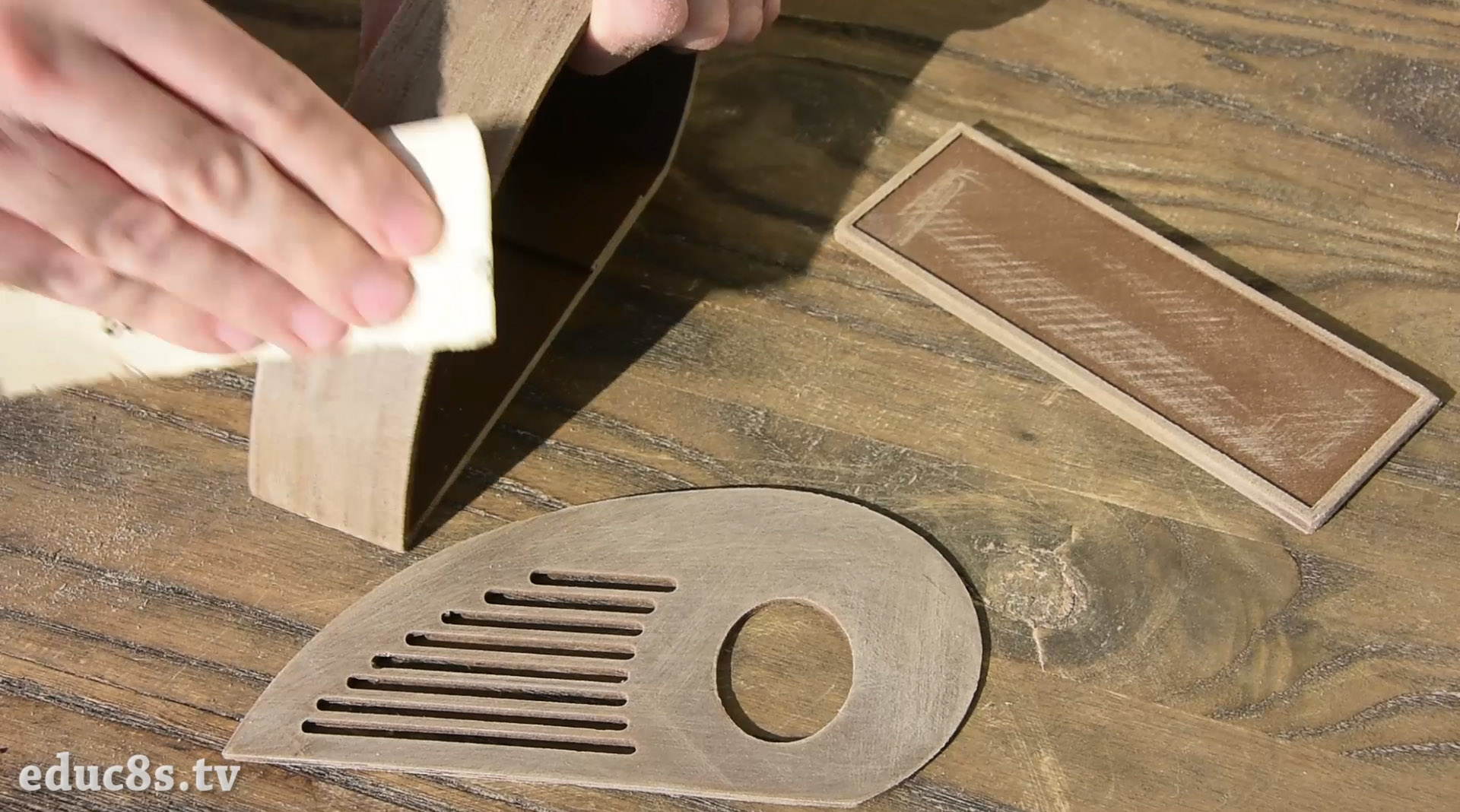
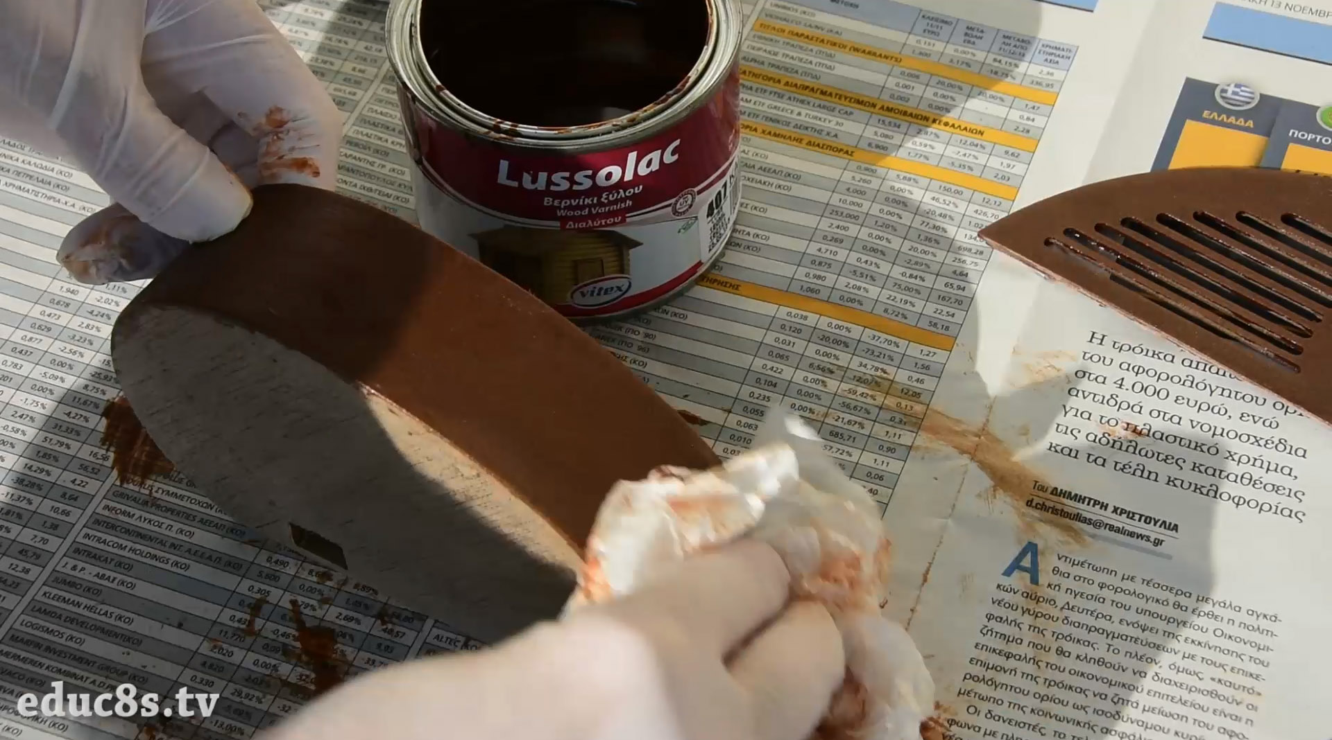
After the print was over, I sanded the parts using fine sand paper. Then polished them using wood varnish. I waited for about a day for the varnish to dry before proceding the project.
The end result is impressive.
Since I am very new to 3d printing my technique for polishing the 3d print may not be ideal, but the end result is really great!
Connecting Everything Together


After the wood varnish was dry, I attached the display to the front piece with some tape and soldered the wires to the Wemos D1 mini board. I then connected the wires to the screen. After testing the circuit again to be sure that everything is working as expected it was time to glue the Wemos D1 mini board in place.
Unfortunately, the design was not perfect and the parts didn’t fit in the enclosure for an error of a couple millimeters, so I had to make some modifications to the design the hard way. The 3D files that I have uploaded are the correct ones, after the modifications were transferred to the 3D design.
Then, I powered up the project and centered the display before attaching it permanently with hot glue. It was then time to glue a small piece of fabric on the front piece in order to add some color and contrast to the enclosure. The last step was to glue all the parts together! Our project is ready! Impressive isn’t it? I really like the shape and the feel of the enclosure. It makes an ordinary Weather Station to look unique. Let’s now see the software side of the project.
The Code of the Project

The project gets the weather forecast from the openweathermap.org website. In order to parse the weather data we need the excellent Arduino JSON library. We also need two libraries for the display.
The libraries needed are the following:
- Adafruit GFX: https://github.com/adafruit/Adafruit-GFX-Library
- Adafruit ST7735: https://github.com/adafruit/Adafruit-ST7735-Libra...
- Arduino JSON: https://github.com/bblanchon/ArduinoJson
Let’s see the code now. At first, we have to set the SSID and the password of our WiFi network. Next, we have to enter the free APIKEY from operweathermap.org website. In order to create your own API key, you have to sign up in the website. Getting current weather data and forecast is free but the website offers more options if you are willing to pay some money. Next, we have to find the id of our location. Find your location and copy the ID which can be found in the URL of your location. Then enter your city’s id in the CityID variable. The last step is to enter your time zone in order for the project to display the correct time. Now we are ready to move on.
At first, we connect to the WiFi Network. Then we request weather data from the server. I only request one result, the weather forecast for the next 3 hours. You can easily modify the code to get more forecast results if you wish. We get a reply with the weather data in JSON format. Before sending the data to the JSON library I manually delete some characters that were causing me problems. Then the JSON library takes over and we can easily save the data that we need in variables. We have to take a look at the structure of the JSON data that the openweathermap website replies to see how to get the data we are interested in. After we have saved the data in variables, all we have to do is to display them on the screen and wait for 30 minutes before requesting new data from the server. We display the time of the weather prediction, the temperature and the weather icon. The weather icons consist of some bitmap graphics and some simple shapes. I have also prepared a version of the code which displays the temperature in degrees Fahrenheit.
You can find the code of the project attached to this Instructable. I order to download the latest version of the code (version 2020) you can check the project's website here: https://educ8s.tv/esp8266-weather-display-art-deco/
or the github repository of the project: https://github.com/educ8s/ESP8266-Weather-Display-with-Art-Deco-enclosure
Downloads
Final Result


As you can see, with the technology now available we can build impressive projects easily and with very low cost! This project is a clear demonstration of this, it costs less than 15$! Of course, we can add many things to this project in order to improve it. We can add a speaker and make it an MP3 player, we can add an FM radio receiver and turn it into a vintage radio and many more things. I would love to hear your opinion about this project. Do you have any ideas on how to improve this project? Please post your thoughts and ideas below. Thanks!