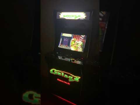
AtGames Legends Arcade Machine Ultimate Mod
by alinke in Circuits > Raspberry Pi
16622 Views, 6 Favorites, 0 Comments
AtGames Legends Arcade Machine Ultimate Mod

An AtGames Legends Arcade Machine with the following modifications:
- LCD Marquee
- LED Base Plate Mounted Marquee
- Mini LED Display (scrolls game titles)
- Mini OLED (display game meta-data)
- LED Strip Accent Lighting
All modifications change dynamically to match the current game and are integrated with the AtGames native OS and add on CoinOps X arcade front end.
Note that other than the Pixecade LED marquee, the other mods in this Instructable are beta and not supported in the production release of the AtGames firmware at the time of this writing.
These features are supported however in the Pixelcade software that is available for other major PC based arcade fronts ends such as CoinOps, LaunchBox/Big Box, HyperSpin, and GameEx and also RetroPie for Raspberry Pi. More info at http://pixelcade.org.
Materials
AtGames Legends 1.0 or 1.1 Arcade Machine
Pixelcade LED Marquee with AtGames Mount
Super PixelcadeLCD Marquee with AtGames Mount - Beta
MAX7219 8 Module LED Matrix (single color)
Alexa enabled Wi-Fi power strip
16 or 32 GB USB Thumb Drive
M3 x 20 Machine Screws (4)
M3 Nylon Nuts (4)
M3 x 40 Machine Screw (2)
M3 Metal Nut (6)
M3 x 14 Machine Screws (8)
M3 Washers (8)
M3 x 11 Hex Stands (4)
Mounting Arduino for Mini Dot Matrix and OLED Displays


The Arduino controls the MAX7219 LED dot matrix and the mini OLED displays. The Arduino is USB connected to the AtGames Legends. The Arduino is mounted inside the control panel case of the AtGames Legends.
Upload this sketch to an Arduino Uno https://github.com/alinke/PIXEL/blob/wip/max7219%2...
Arduino Pins Connections
MAX7219 LED Matrix (8 Module)
DIN--> 9
CS-->8
CLK--> 7
Mini OLED
SCL--> SCL
SDA--> SDA
Pixelcade LED Base Plate Mount


The stock Pixelcade LED mount for the AtGames Legends can be used for the base plate mount as well.
Use the Pixelcade LED mount to cut out the area for the LED matrix and mounting holes.
I tried to maintain the original artwork but it got scratched up pretty bad after cutting out the holes so ended up just painting over with black paint.
Common Power Strip


Pixelcade LED, Super PixelcadeLCD are both plugged into an Alexa WiFi power strip. The AtGames Legends 12V power supply is also plugged into this power strip such that the entire system can be turned on and off with Alexa comamnds.
Mounting Mini OLED Display on Control Panel


Mounting the mini OLED on the control panel of the AtGames Legneds. The mini OLED displays game meta-data such as title, year, manufacturer, and parental rating. The mini OLED is connected to the Arduino
Wiring & Mounting Accent Lighting LED Strip
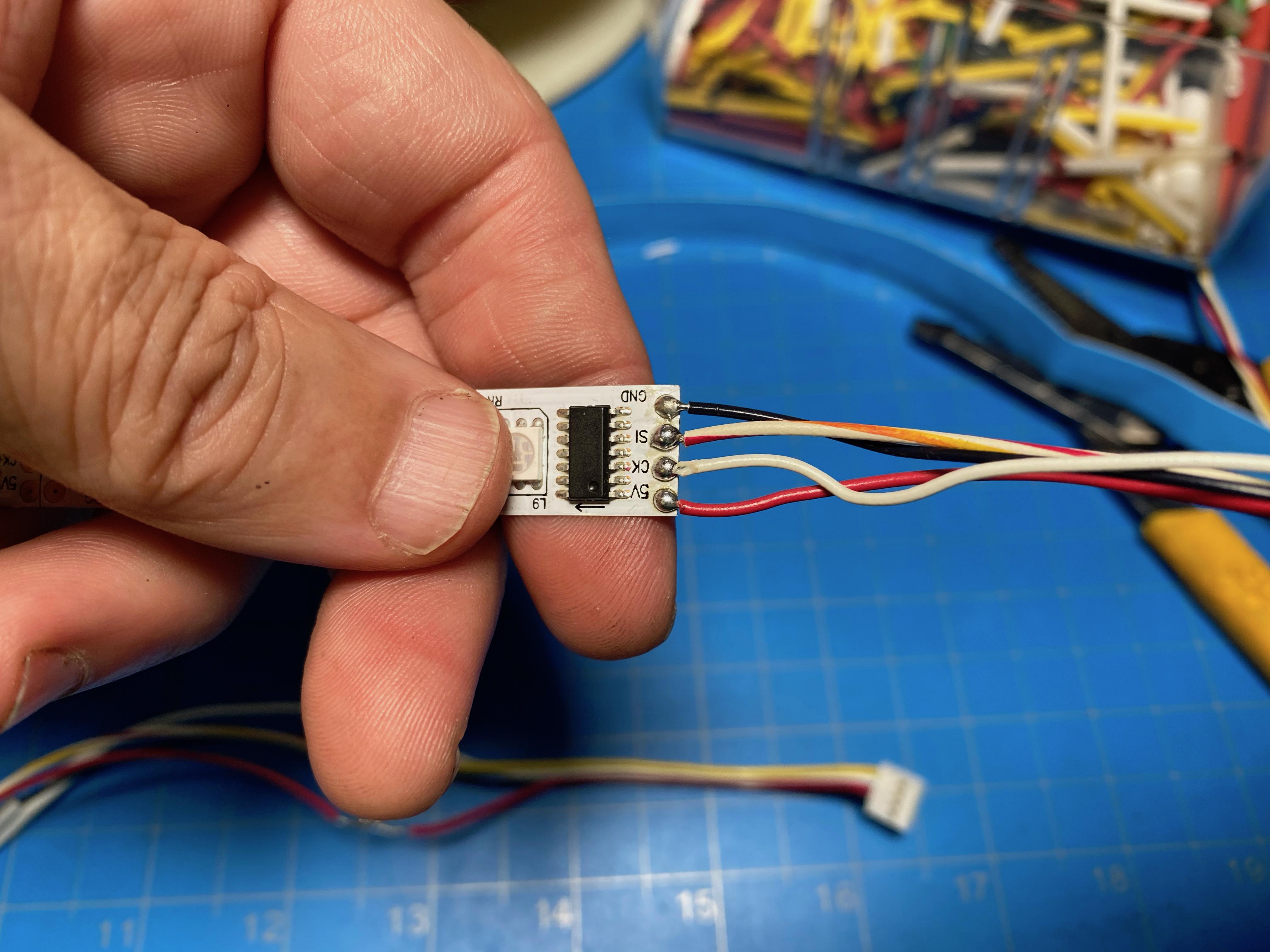


The accent lighting via the LED strip will change dynamically to match the dominant color of the marquee of the select game.
Note only a WS2801 LED strip can be used. Pixelcade is not compatible with WS281X based strips.
Solder 4 wires to the LED strip (+5V, GND, and two data signal wires) to a Grove connector. The Grove connector then plugs into Pins 2 and 3 of the Grove connector on the Pixelcade PCB board.
Connecting Pixelcade LED
Follow the video to connect and setup Pixelcade LED to your AtGames Legends (ALU).
Note that if you have an ALU 1.1, you can connect Pixelcade's USB wire inside your cabinet and if you have an ALU 1.0, you'll need to route the USB cable outside of your cabinet and plug into the control panel's right USB port.
Installing and Setting Up Super PixelcadeLCD Marquee

Follow the video to install and setup the Super PixelcadeLCD marquee.