Automatic Alarm System for Outdoor Use That's Gravity-Driven and Can Deter Intruders or Be Configured to Create Rotary Power
60 Views, 1 Favorites, 0 Comments
Automatic Alarm System for Outdoor Use That's Gravity-Driven and Can Deter Intruders or Be Configured to Create Rotary Power
.png)
This design is for a backyard or camping scenario to help prevent intruders from jumping over a fence and going onto someones property or general area.
It should be noted that this can also be used to create rotational power through the dropping of a weight connected to an axle and does not need a trigger to be operated... but for the time being the description will be geared toward security in a camping or outdoor type scenario where something triggers the potential energy of a weight connected to an axle to cause rotational energy.
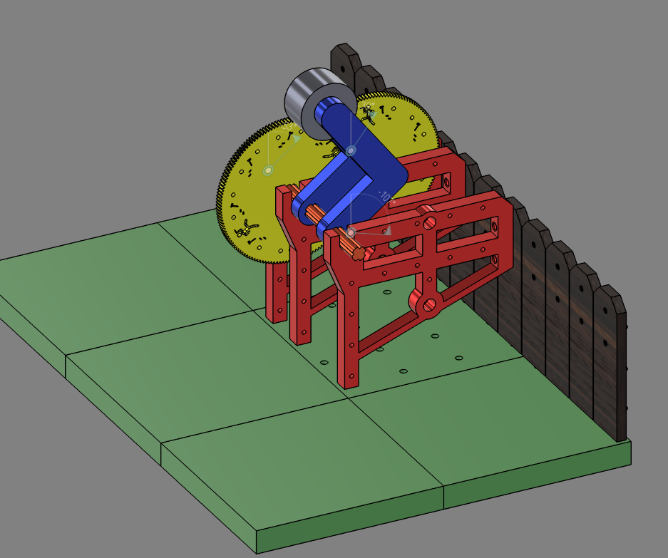
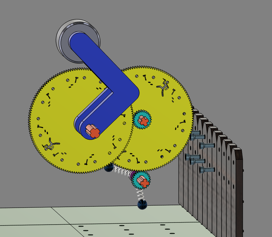
The current design can attach to a fence, or other structure, and if the supporting fence is moved, such as what would happen if someone tries to climb or scale the fence, then the movement of the fence will cause a weight to swing downward, which in turn spins an axle, and through multiple gear ratios, will spin a secondary axle and then a third output axle that can be used to signal that the trap has been triggered. In the current iteration the alert is the rotation of a mallet that swings into a bell to alert people that there is an intruder... or intruder equivalent, like a bear I guess.
(While the description will mention fences a lot, one could also rig it so it can be mounted on anything and movement or shaking of any kind can jostle the structure and create rotations of an axle)
How It Works - The Mechanics involved
The core of this is what's called a gravity drive — essentially the same principle that powered mechanical clocks for centuries before electricity existed. A weight on an arm is attached rigidly to an axle. The weight is positioned roughly 180 degrees in the air, with its center of mass directly over the axle. If nothing disturbs it, the arm won't swing down and the axle won't turn.
The arm in this configuration is functioning as an inverted pendulum — balanced at the top of its arc rather than hanging at the bottom like a normal pendulum. That balance is inherently unstable, which is exactly what makes it useful as a trigger: any disturbance that shifts the center of mass past the balance point causes the arm to fall, and once it starts, there's nothing stopping it.
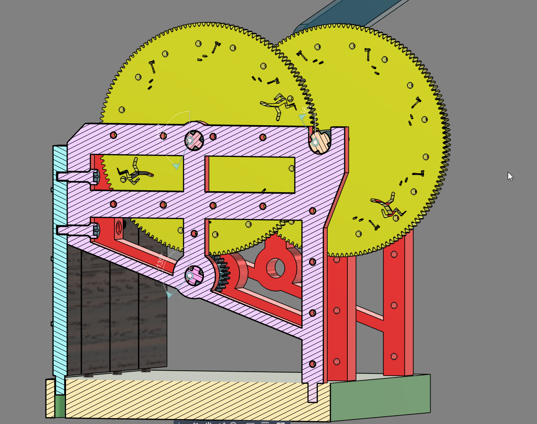
If someone moves the fence, as would happen if someone tried scaling it, it will cause the structure connected to the fence to shake. That shaking shifts the weight off its balance point. When this happens, the gravity of the weight falling causes the main axle to turn. You then put that rotation through gear ratios (in this model it's a 144 tooth gear interacting with a 24 tooth gear, or 6:1, and then another 6:1 ratio resulting in 36:1 total) to amplify the speed of rotation at the output.
Additionally, you could also put this through an escapement mechanism to have it do work over a long period of time depending on how much weight is used on the main axle, (same concept as the weight-driven clock trains that kept time in towers before any electronics existed. That's a whole other configuration but worth mentioning because the same hardware supports it.)
Reset
After the weight has fallen, to reset it, someone just needs to rotate the weight back to the top of the cycle and position it so it's right over the axle and doesn't fall. Or if using it as an escapement mechanism and not an alarm, position it so the center of mass is slightly beyond the axle and allow the arm to rotate downward and generate rotation over time.
(A simple jig could also be used or implemented to align the arm to get it to balance quicker, but mostly that's not a huge problem.)
Many Configurations
The current configuration was designed to demonstrate it attaching to a fence, so when the fence is interacted with the output axle, which has a spring mallet, will rapidly rotate into a bell, alerting people that someone is trying to get over the fence. And while this will work in that scenario, there are many different configurations to this concept and things that can be attached to the output axle.
In an outdoor/camping environment, one could also use the rotation of the output axle to do many different things — spin a rotisserie, drive a small generator, trigger a signal of some kind, or run it through an escapement and produce sustained controlled rotation for whatever mechanical task needs doing. Or not use it for security at all, and just use the dropping weight as a low-tech off-grid power source.
The concept can also be used beyond just attaching to a fence for security — placing it on anything you want to be alerted to when it moves works the same way. A door, a gate, a cooler lid, a tent zipper... anything.
Supplies
-3d printer
-filament (probably ABS would be better, or any filament that would be good in outdoor environments)
-#8 screws (roughly .17 inch diameter)
-some fence or structure to attach this to (assuming you wanted to actually make a real one and not a model of one.)
Bell of some kind (if used as an alarm, a cheap small metal bell would work pretty well, alternatively you could always not do that and have the output axle do something else, in which case that's fine.)
3d Print the Files
assuming you wanted to use my exact design then printing the stl files would be a good start.
(which you are free to do, I put all my stuff in the public domain for anyone to do whatever they want with them, I also allow anyone to modify my fusion 360 file to try to modify it and make it their own... no licensing or payment necessary, I just like to make things and don't like things being behind paywalls or barriers to entry.)
(CC:BY-SA-4.0)
While this was a prototype with the limitations of my 3D print bed volume, these can be scaled up. You can also assemble a similar structure using PVC pipes and couplings to create roughly the same effects if printing isn't an option.
Secure the Structure to the Fence
.png)
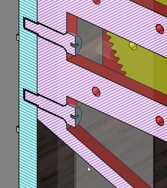
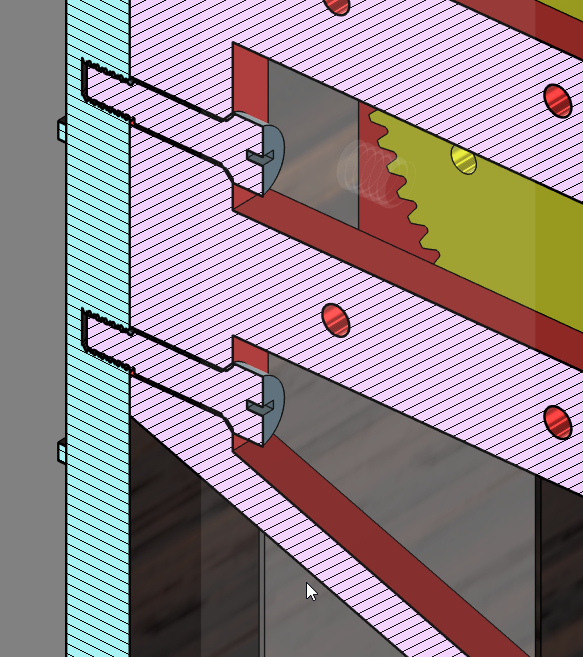
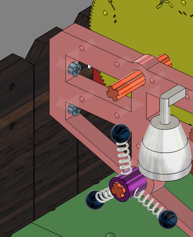
Use #8 screws and secure the structure to the fence — or whatever you want to secure it to — so that when it moves it will cause the weight to fall and rotate.
The frame has two points of contact:
one part attaches to the fence, and the other point of contact are posts which sit on the ground. The attachment to the fence keeps the structure from swaying when at rest, and the base posts just need to contact the ground to keep the frame from tipping forward. The main axle, and weight, are positioned under the base posts, so that while it is allowed to sway when interacted with, at rest it's fairly stable and won't tend to move. Anchoring the posts would add a third point of contact and would make the alarm component less likely to trigger if the fence (or whatever one attaches it to) is shaken by something.
Setup the Weight and the Axles
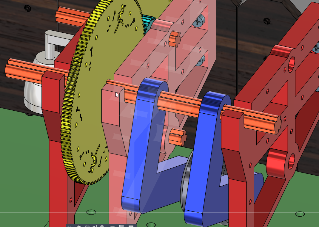
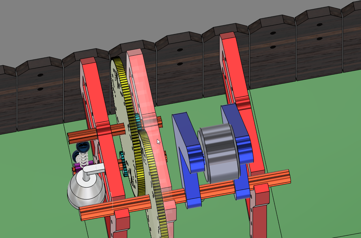
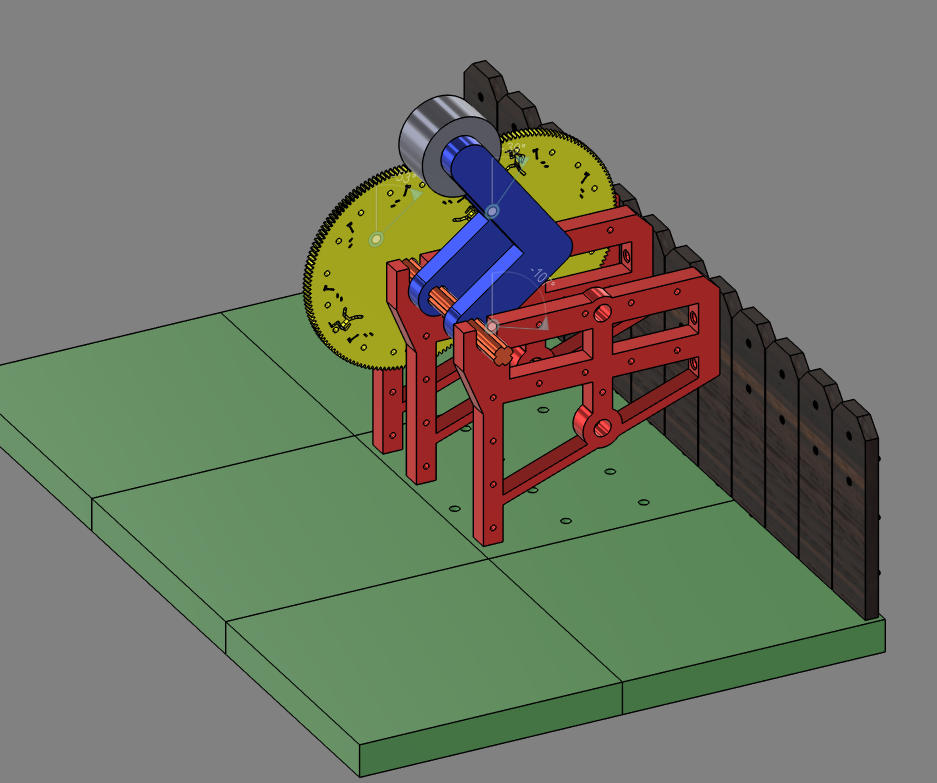
- Slide the long axle through the weighted arm so it's roughly centered
- Put the 144-tooth gear on one end of the axle
- Lift the axle and place it in the groove on the frame
- Test the axle and make sure it spins with minimal friction
For the purposes of it being used as an alarm when something causes the structure to move, it can be useful to have at least some friction in the axles just so that it's less likely to have a false alarm like a breeze to trigger the mechanism.
(Some slight friction is recommended because if placed well the arm will balance at the top and is less likely to fall spontaneously from wind. You want it to require actual structural movement to trigger, not just a breeze.)
Assembling the Intermediate Gear Ratio (6:1)
.png)
.png)
.png)
.png)
-Slide the intermediate axle through the first hole on the frame
-Slide it through the 24-tooth gear
-Push it through until it seats in the hole on the opposite side
-Check that the 144-tooth gear on the main axle meshes well with the 24-tooth gear on this axle
(if there are issues with meshing, either the teeth are too close together creating friction, or too far apart allowing the teeth to slip, consider scaling up or down the 144 tooth gear to 102% or 98% to try to optimize mesh as printer variations can cause issues with meshing, especially for gears and the effects of weathering.)
Assemble the Output Gear Ratio and Axle (36:1)
.png)
.png)
.png)
.png)
Same process as before:
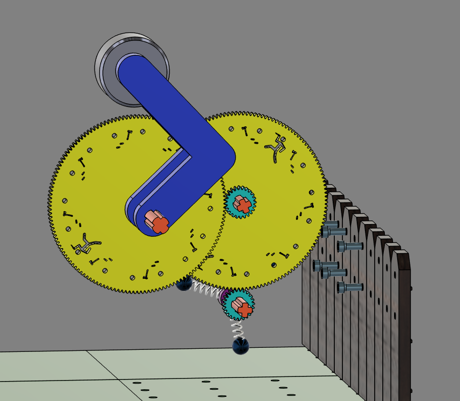
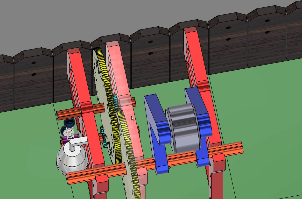
-Slide the output axle through one hole, through the 24-tooth gear, and into the far hole
-Check for smooth spin with minimal friction
-Mesh the 144-tooth gear on the intermediate axle to this 24-tooth gear on the output axle
For the alarm configuration:
-Slide the spring mallet component onto the output axle so it rotates with it
-Position a bell so that when the output axle rotates and the mallet spins, it hits the bell and creates a ringing sound
-When the weight arm falls and drives the gear train, the mallet will rapidly spin through its 18 output rotations and ring the bell repeatedly
If you're using this for something other than an alarm, such as a rotisserie, an escapement, a generator, a signal mechanism, or anything else that needs rotation , just skip the mallet and bell components and attach whatever works for your use case to the output axle instead.
The output rotation can be the same as the one in this project or you can change the gearing ratios depending on the purpose of the design and the requirements for the speed of rotation or amount of torque.
DISCLAIMER:
I'm not responsible if anything goes horribly wrong.
Good luck and have fun making things.