Automatic Watering System for Plants
by allaine_sioson in Living > Gardening
276 Views, 0 Favorites, 0 Comments
Automatic Watering System for Plants

This is an automatic plant watering system, it detects when the soil is too dry for the plant and refills the water. It also has an ultrasonic sensor to detect the level of the water in the tank if it needs to be refilled and a TMP sensor to detect the temperature of the surroundings and if it's too hot or cold for the plant.
Supplies
Materials:
- Arduino UNO
- 1x Breadboard
- 1x Soil Moisture Sensor
- 1x Ultrasonic Sensor
- 1x TMP Sensor
- 1x 330Ω Resistor
- 1x RGB LED
- 1x I2C LED
- 1x Micro Servo
- 1x Plant Pot
- 1x Water/Soda Bottle
- 1x Straw (Metal)
- 12x Wooden Blocks (3in x 1in x 1in)
Materials for Construction:
- Hot Glue
- Duct Tape
- Electrical Tape
- Masking Tape
- String
Tools Required:
- Hot Glue Gun
- Box Cutter
- Scissors
- Paint (design purposes)
Wiring the Ground/Power
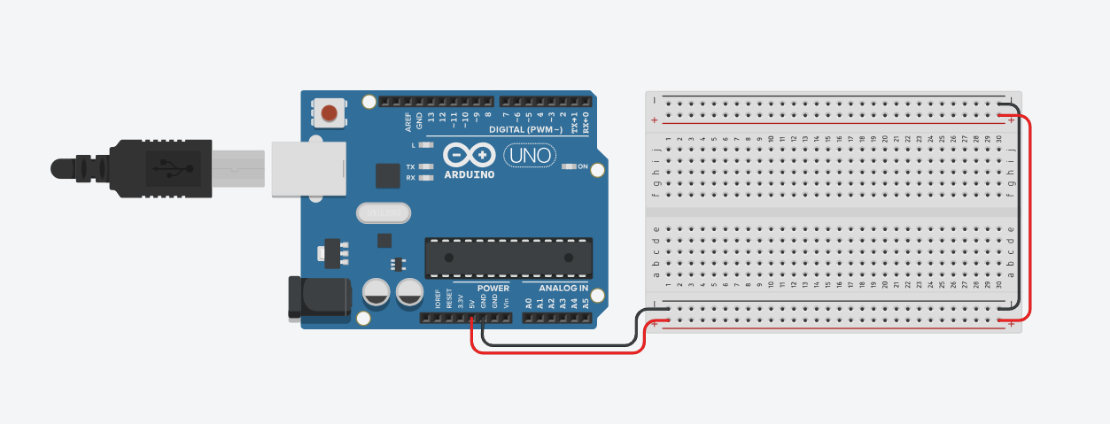
Wiring the breadboard to the Arduino UNO:
- To connect the breadboard to the power, insert a robot wire pin into the 5V port in the Arduino. The opposite end pin goes into the positive spot in the breadboard. (Please view red wire connected to the Arduino for reference)
- To connect the breadboard to the ground, insert a robot wire pin into the GRD port in the Arduino. The opposite end pin goes into the negative spot in the breadboard. (Please view black wire connected to the Arduino for reference)
Connecting both sides of the breadboard:
- Since we will be using the other half of the breadboard too, we will connect both sides with wires. Plug a wire into the positive spot on the breadboard and the other end of the wire into the opposing positive spot on the breadboard. (Please view red wire on the right side for reference)
- Then, plug a wire into the negative spot on the breadboard and the other end of the wire into the opposing negative spot on the breadboard. (Please view black wire on the right side for reference)
- This will allow anything plugged into the other half of the breadboard to reach the Arduino.
Create a Lantern (Status Indicator)
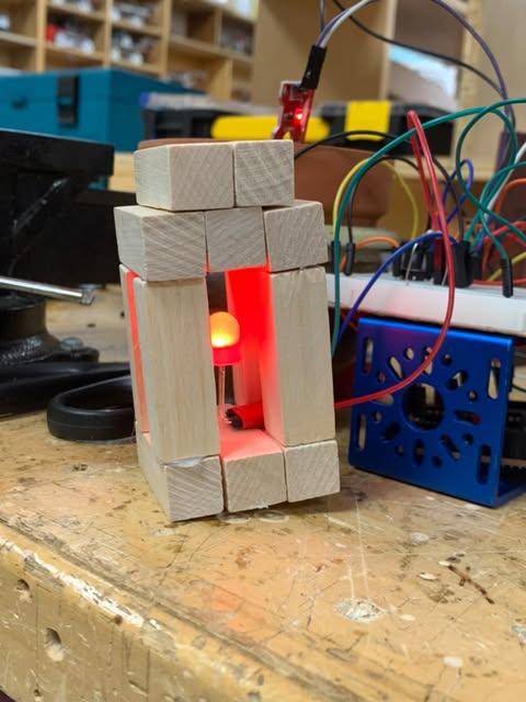
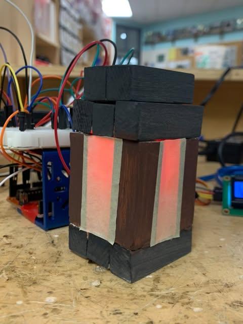
Creating the Base:
- Glue 3 wooden blocks together with hot glue to act as the base of the lantern.
- Attach 1 wooden block standing vertically on each corner of the base with hot glue, these will act as the pillars of the lantern.
- Then, repeat step one and hot glue it to the top of the pillar blocks.
- Glue the final 2 pieces of wood on top, placing it in the centre.
Attaching the RGB LED:
- Place the RGB LED inside the lantern, bend the wires so that it sticks out of the lantern while the LED stands upright inside.
- Attach robot wires to the LED pins and tape them together with electrical tape.
- Hot glue the electrical taped section onto the base.
Designing (OPTIONAL):
- Paint the "pillar blocks" with brown paint and the base and top sections with dark grey paint.
- Place masking tape on top of each gap to mimic the tinted window of the lantern, allowing the light to pass through but hides the RGB LED.
Wiring the Lantern
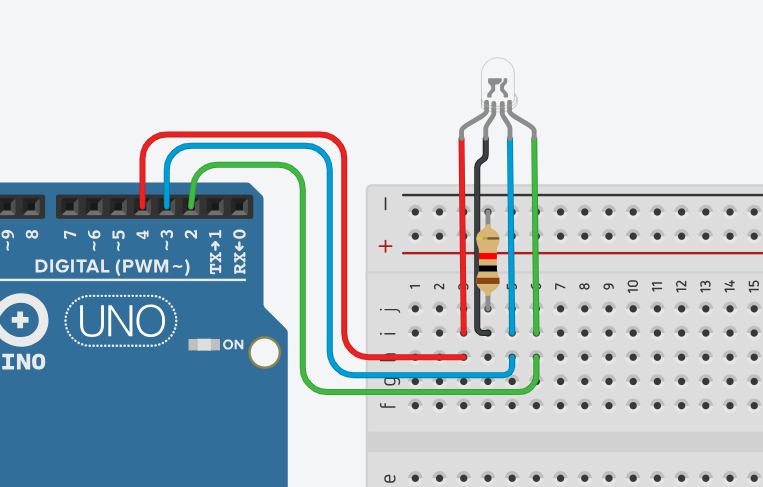
Wiring the LED to the breadboard:
- Attach the red pin of your LED with a wire into the i3 spot of the breadboard.
- Attach the blue pin of your LED with a wire into the i5 spot of the breadboard.
- Attach the green pin of your LED with a wire into the i6 spot of the breadboard.
(NOTE: If your LED appears to be cloudy / translucent, you most likely have a common anode, if it's clear, then it's a common cathode.)
If you have a common CATHODE:
- If you have a cathode LED plug your one of your resistor pins into the negative spot and the other in j4.
- Attach the GRD pin of the LED with a wire into the i4 spot of the breadboard.
If you have a common ANODE:
- If you have an anode LED, plug your one of your resistor pins into the positive spot and the other in i4.
- Attach the POWER pin of the LED with a wire into the h4 spot of the breadboard.
Wiring to the Arduino:
- To connect the red pin of the LED to the Arduino, insert a wire into digital pin 4 and the other end of the wire into the h3 spot of the breadboard.
- To connect the blue pin of the LED to the Arduino, insert a wire into digital pin 3 and the other end of the wire into the h5 spot of the breadboard.
- To connect the green pin of the LED to the Arduino, insert a wire into digital pin 2 and the other end of the wire into the h6 spot of the breadboard.
Creating the Water Tank / Dispenser
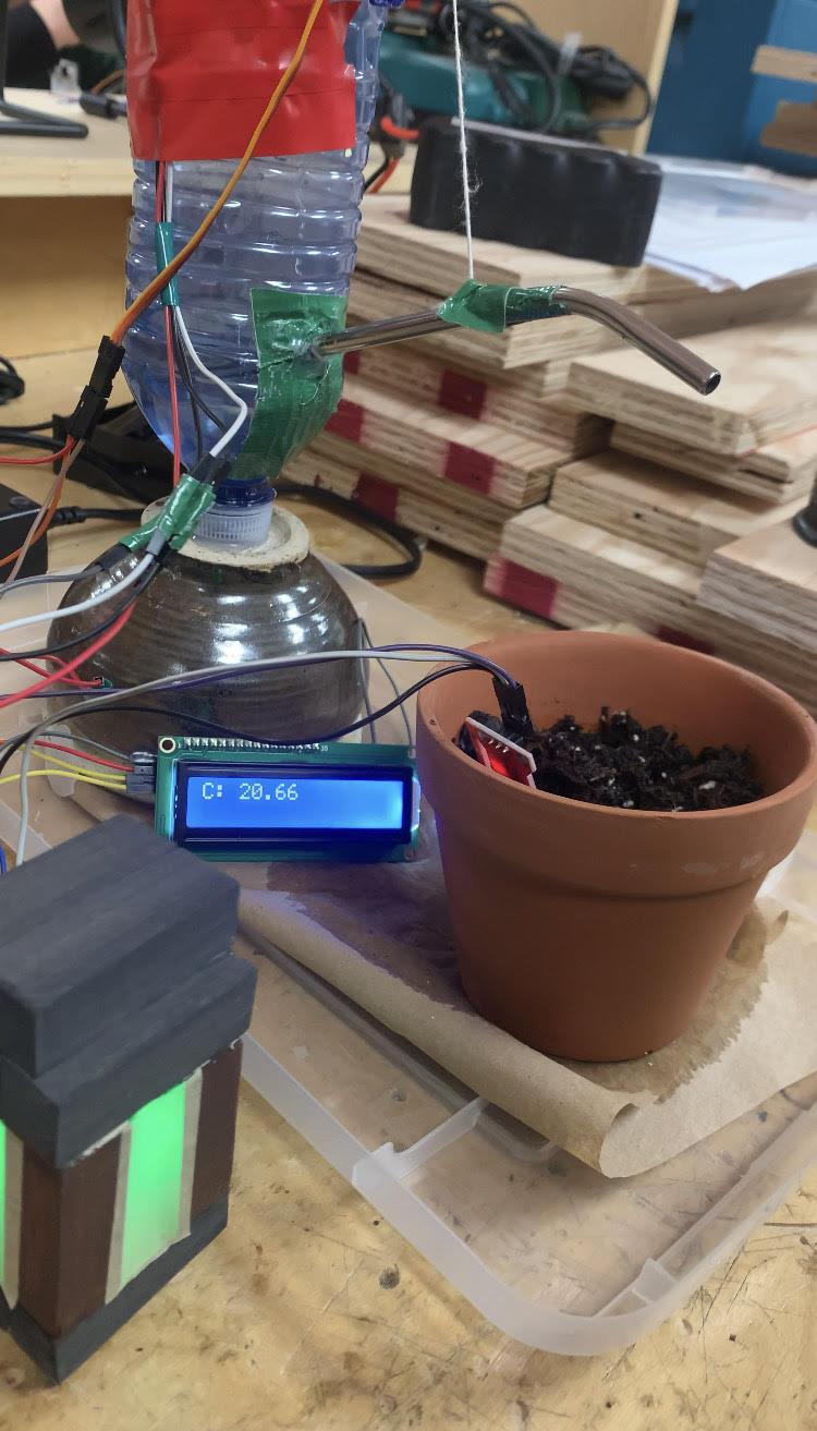
Building the Tank / Dispenser:
- Cut 1/2in to 1in off either the top or the bottom of the bottle with a cutter. (I cut off the bottom)
- Attach a micro servo onto the side of the bottle where the dispenser would be located, hot glue it 1/2in below the top of the tank.
- Create a small hole wherever you'd like the "dispenser" part of the water tank to be and put a straw through the hole.
- Hot glue or tape the straw to one end of a string and the other end to the servo. (please make sure that when you attach it, the servo horn is standing upright and the string is glued to the bottom end of the horn.)
- Place hot glue in the gaps between the straw and the bottle to prevent leakage.
- Attach an ultrasonic sensor to the very top of the tank, facing inside the tank to monitor the water level. Tape it with electrical tape.
Designing (OPTIONAL):
- Place masking tape around the bottle.
- Paint the bottle brown.
- Paint dark brown lines vertically across the bottle.
- Paint on 2 black horizontal lines / place 2 black tapes horizontally around the bottle.
Wiring the Water Tank / Dispenser

Wiring the Ultrasonic Sensor to breadboard:
- Attach the Ultrasonic sensor's POWER pin to the breadboard with a wire into the positive spot on the breadboard.
- Attach the Ultrasonic sensor's GRD pin to the breadboard with a wire into the negative spot on the breadboard.
- Attach the Ultrasonic sensor's TRIG (Trigger) pin to the breadboard with a wire into the j10 spot on the breadboard.
- Attach the Ultrasonic sensor's ECHO pin to the breadboard with a wire into the j11 spot on the breadboard.
Wiring the Micro Servo to breadboard:
- Attach the Micro servo's POWER pin to the breadboard with a wire into the positive spot on the breadboard.
- Attach the Micro servo's GRD pin to the breadboard with a wire into the negative spot on the breadboard.
- Attach the Micro servo's SIGNAL pin to the breadboard with a wire into the j23 spot on the breadboard.
Wiring to the Arduino:
- To connect the Ultrasonic sensor's TRIG pin, insert one end of a wire to the digital 9 pin on the Arduino and the other end into the i10 spot on the breadboard.
- To connect the Ultrasonic sensor's ECHO pin, insert one end of a wire to the digital 8 pin on the Arduino and the other end into the i11 spot on the breadboard.
- To connect the Micro servo's SIGNAL pin, insert one end of a wire to the digital 11 pin on the Arduino and the other end into the i23 spot on the breadboard.
Wiring the TMP Sensor
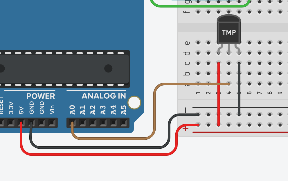
Wiring the TMP Sensor :
- Attach the TMP sensor's POWER pin to the breadboard with a wire into the positive spot on the breadboard.
- Attach the TMP sensor's GRD pin to the breadboard with a wire into the negative spot on the breadboard.
- Attach the TMP sensor's Centre pin to the Arduino with one end of the wire into the analog input pin 0 (A0) port on the Arduino and the other end into the a4 spot on the breadboard.
Wiring the Button

Wiring the Button :
- Attach each pin of the button to the breadboard in spots f13, f15, e13 and e15.
- Connect one of the button's "a" terminal pins to the Arduino with one end of the wire into the digital pin 5 port on the Arduino and the other end into the g15 spot on the breadboard.
- Connect the diagonal opposing pin of the previous "a" pin to the breadboard with one end of the wire into the negative spot on the breadboard for GRD and the other end into the d13 spot.
Wiring the Soil Moisture Sensor

Wiring the Soil Moisture Sensor:
- Attach the sensor's POWER pin to the breadboard with a wire into the c20 spot on the breadboard.
- Attach the sensor's GRD pin to the breadboard with a wire into the negative spot on the breadboard.
- Connect the Arduino to the sensor's power with one end of the wire into the digital pin 10 port on the Arduino and the other end into the d20 spot on the breadboard.
- Connect the Arduino to the sensor's signal pin with one end of the wire into the analog input pin 1 (A1) port on the Arduino and the other end into the signal pin of the sensor.
Wiring the I2C LCD
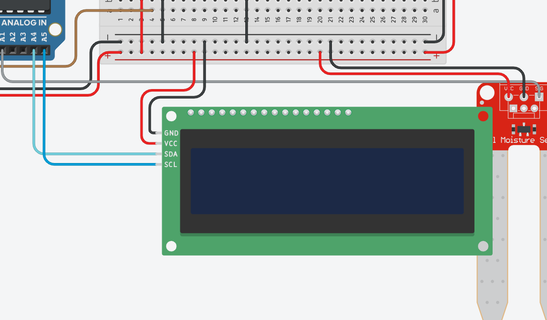
Wiring the Display:
- Attach the display's POWER pin to the breadboard with a wire into a positive spot on the breadboard.
- Attach the sensor's GRD pin to the breadboard with a wire into a negative spot on the breadboard.
- Connect the Arduino to the sensor's SDA pin with one end of the wire into the analog input pin 4 (A4) port on the Arduino and the other end into the SDA pin of the sensor.
- Connect the Arduino to the sensor's SCL pin with one end of the wire into the analog input pin 5 (A5) port on the Arduino and the other end into the SCL pin of the sensor.
Coding the Project
Copy paste this code into the Arduino IDE.