BLE Racing Simulator
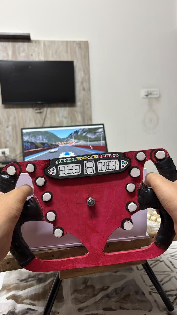
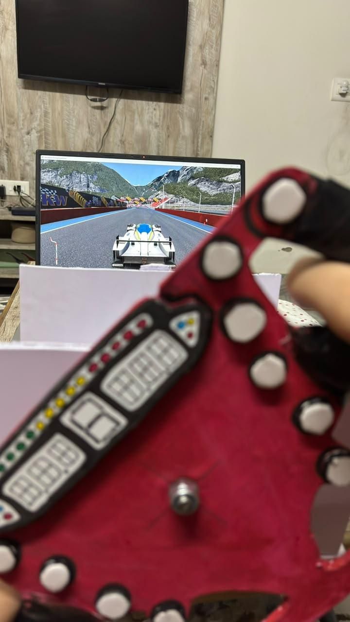
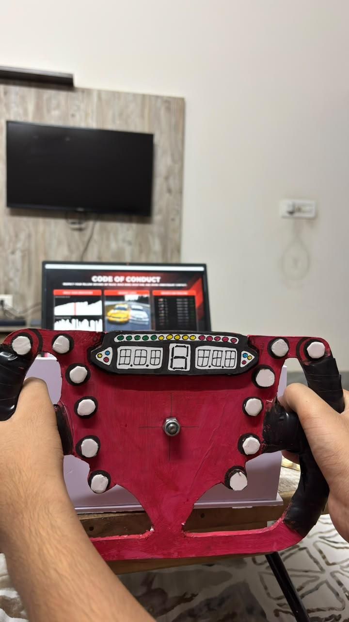
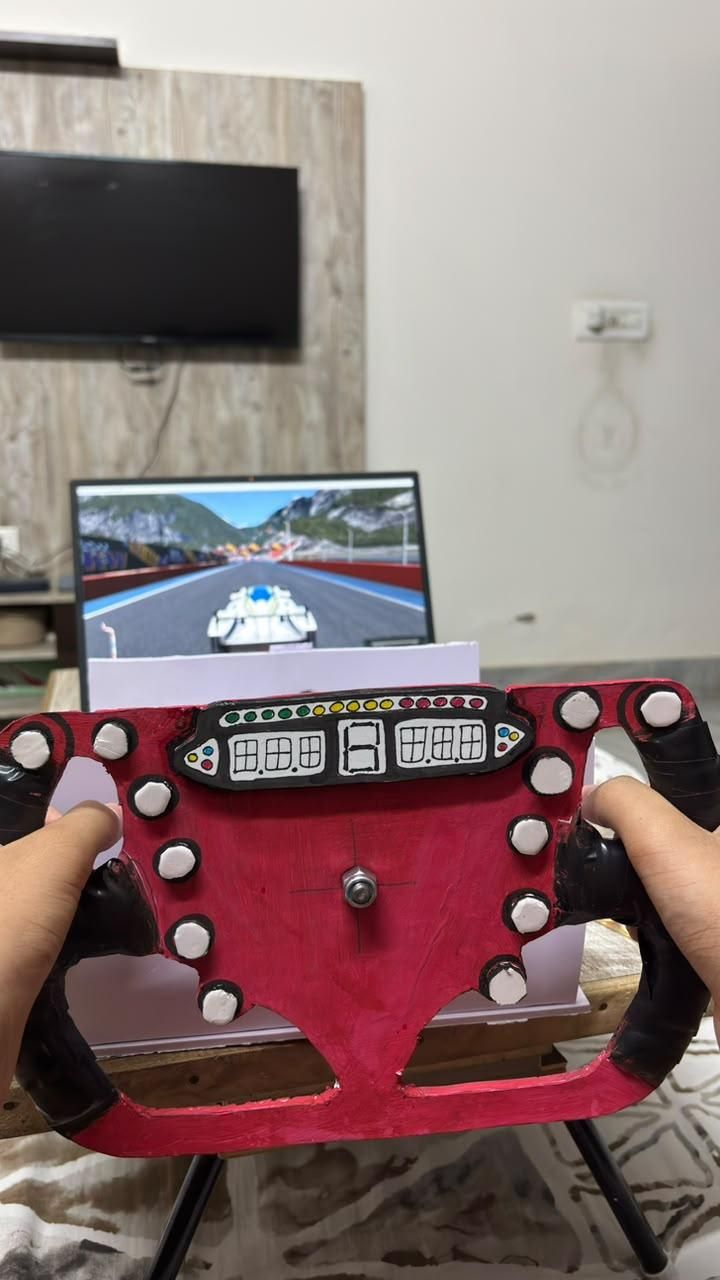
Are you tired of using your keyboard to play racing games? Take your racing experience to the next level by helping me construct this do-it-yourself racing simulator setup!
For games like RaceRoom Racing Experience and iRacing, we will build a steering wheel, pedals, and paddle shifter in this project. The best part is that you don't need a 3D printer to make it—you can do it using basic tools and materials.
Whether you're a racing fan or just looking for a fun electronics project, this build will provide you with a much more immersive driving experience without costing hundreds of dollars in commercial racing hardware.
Supplies
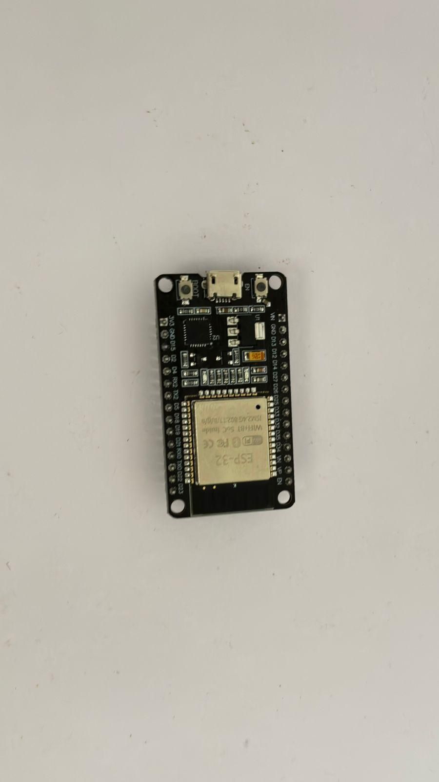
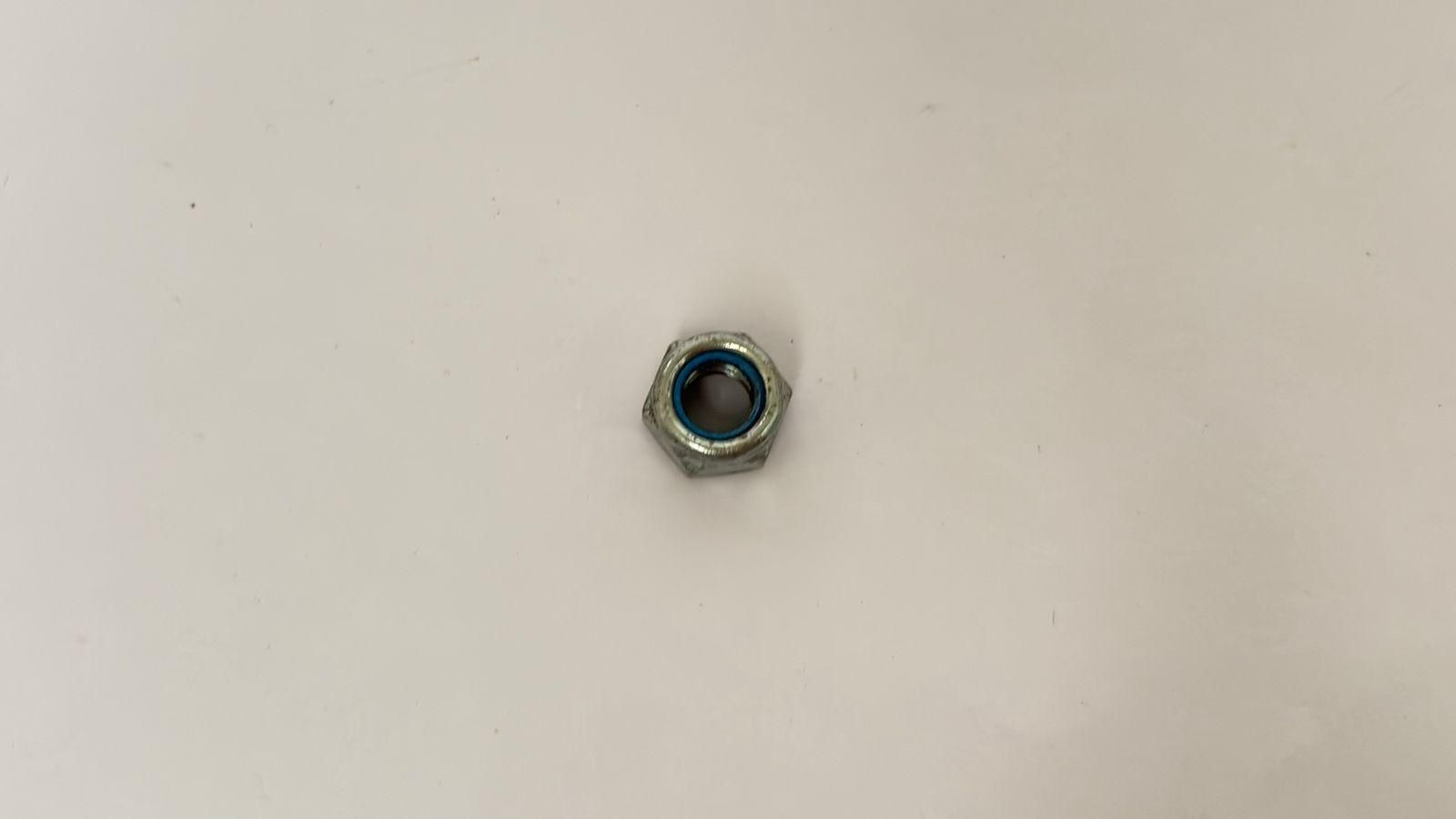
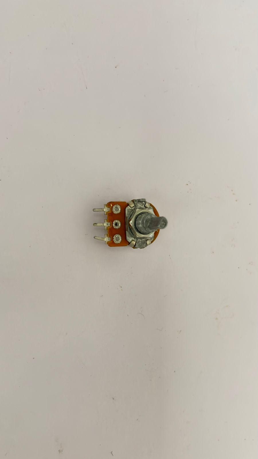
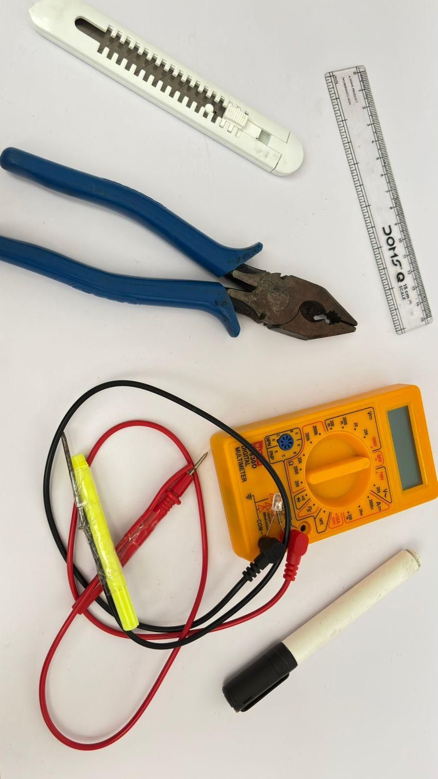
Material -
Electronics-
- ESP32 DOIT DevKit - amazon link
- 10 kΩ Rotary Potentiometer ×1 - amazon link
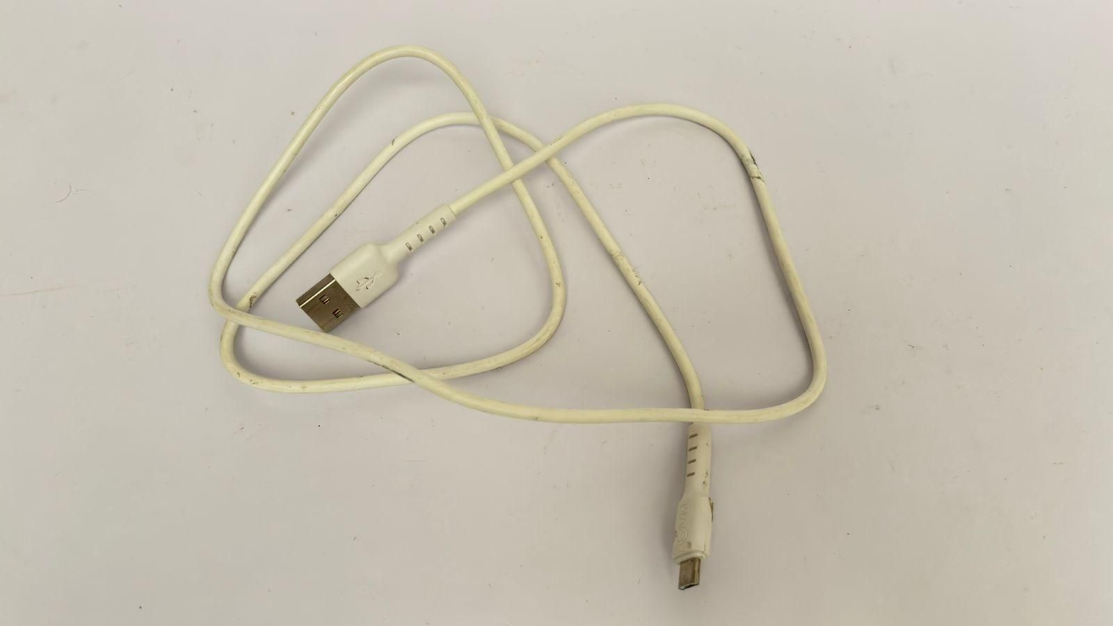
- Micro USB Data Cable ×1 - amazon link
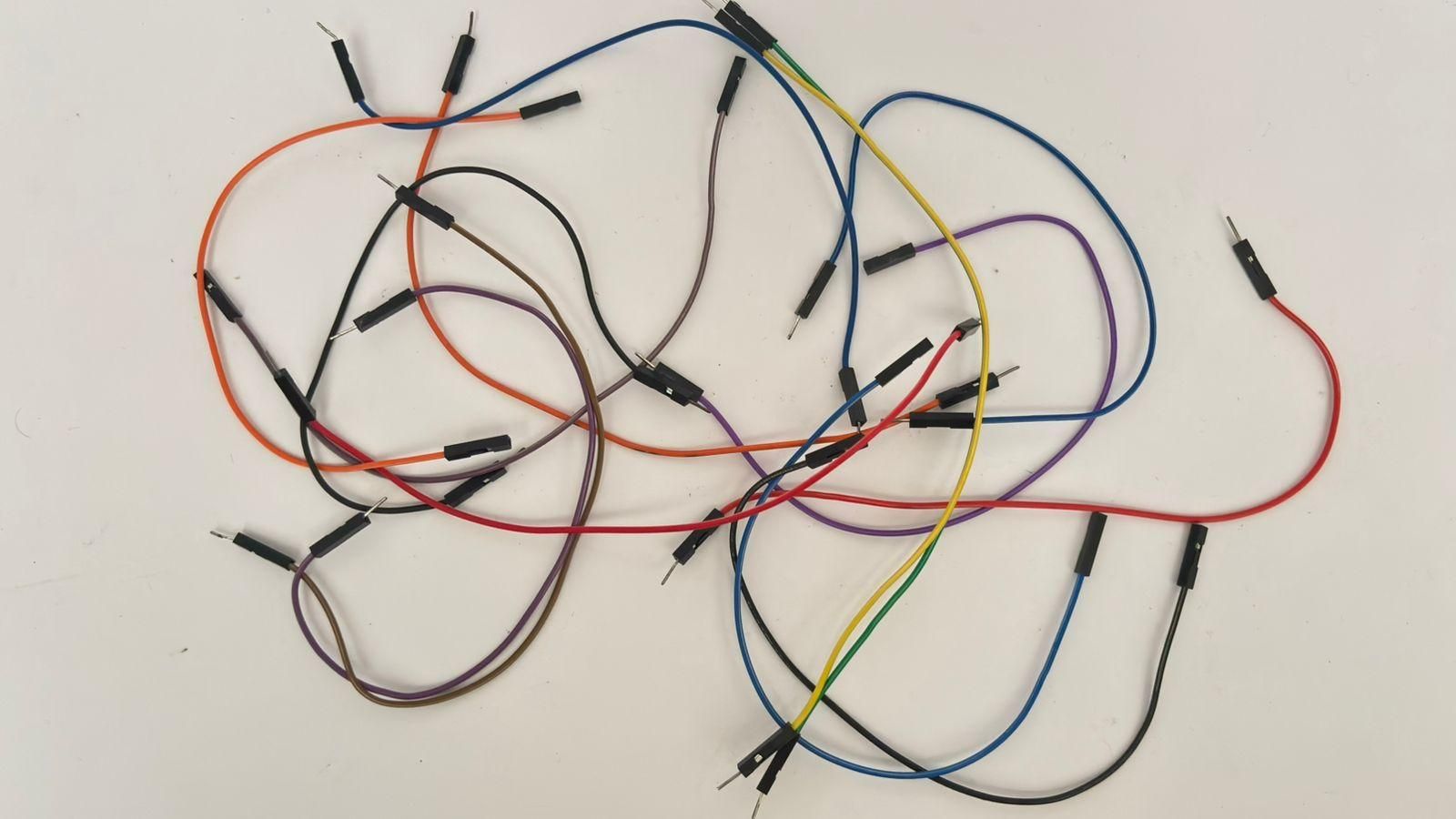
- Jumper Wires (for prototyping) - amazon link
- Linear Potentiometer ×3- amazon link
- Push Buttons ×2 - amazon link
- 18650 Battery Holder ×1 - amazon link
- 18650 Battery ×1 - amazon link
- TP4056 Charging Module ×1 - amazon link
- MT3608 Boost Converter ×1 - amazon link
- Toggle Switch ×1 - amazon link
- Heat Shrink Tubing - amazon link
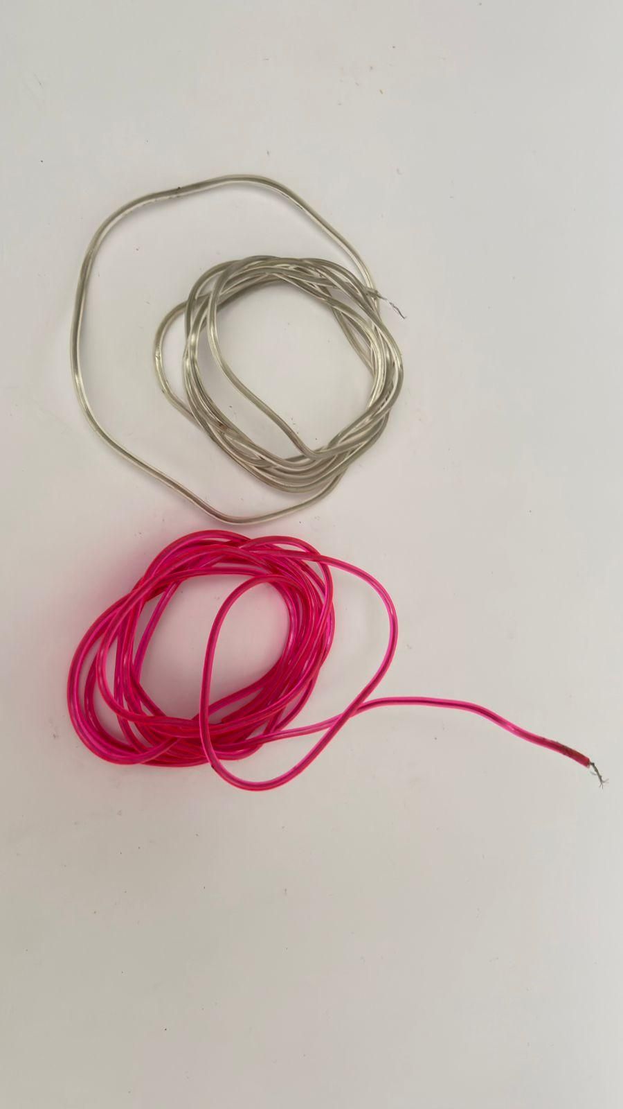
- Hook-up Wire - amazon link
Mechanical Parts-
- Foam Sheet (20 mm thick) - amazon link
- Sun Board (5 mm thick) - amazon link
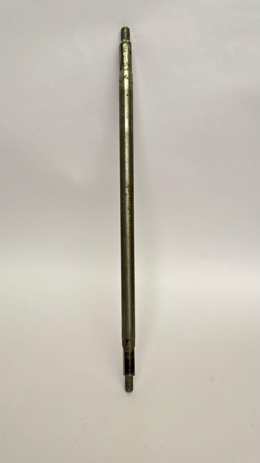
- Rod (I couldn't find the exact rod I'm using.) You can use any rod that is approximately 30–32 cm long. Make sure it has threads on one end so that the steering wheel can be easily removed and attached.
- Compression Spring (recommended: 100 mm length, 1.5 mm wire diameter) X 3 - amazon link
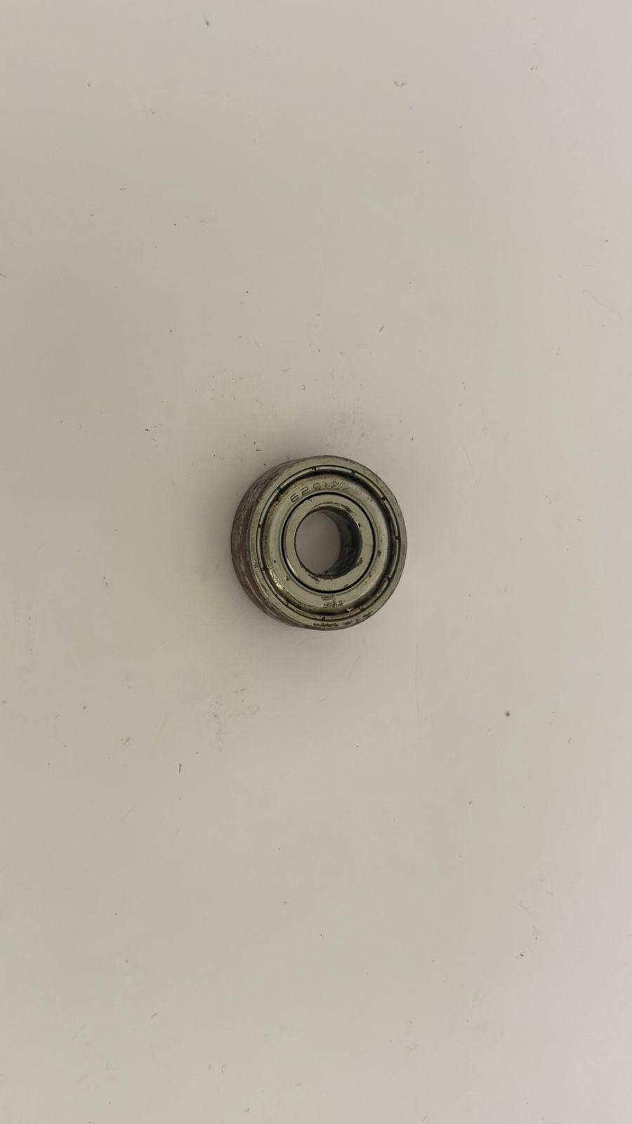
- Bearing (Optional) – Choose a bearing with an inner diameter that matches the rod you are using.
- Nut – Choose a nut that is compatible with the threaded end of your rod.
Consumables-
- Paint and Colors (optional)
- Glue for Sun Board - amazon link
tools -
- Multimeter - amazon link
- Ruler - amazon link
- Cutter Knife - amazon link
- Marker - amazon link
- Scissors - amazon link
- Soldering Iron - amazon link
- Wire Cutter - amazon link
Making the Wheel
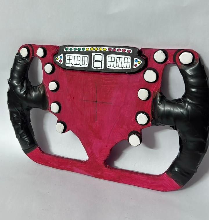
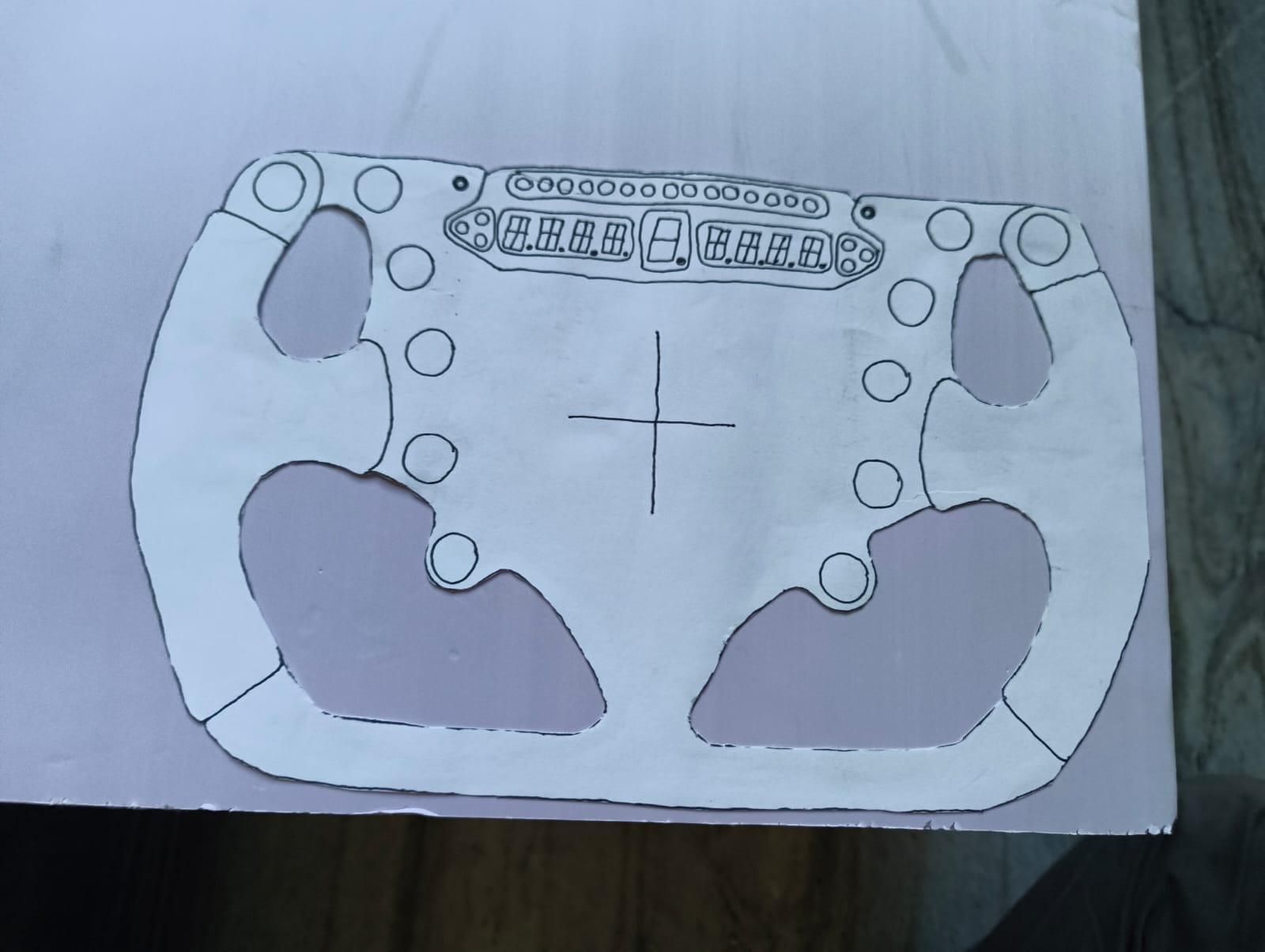
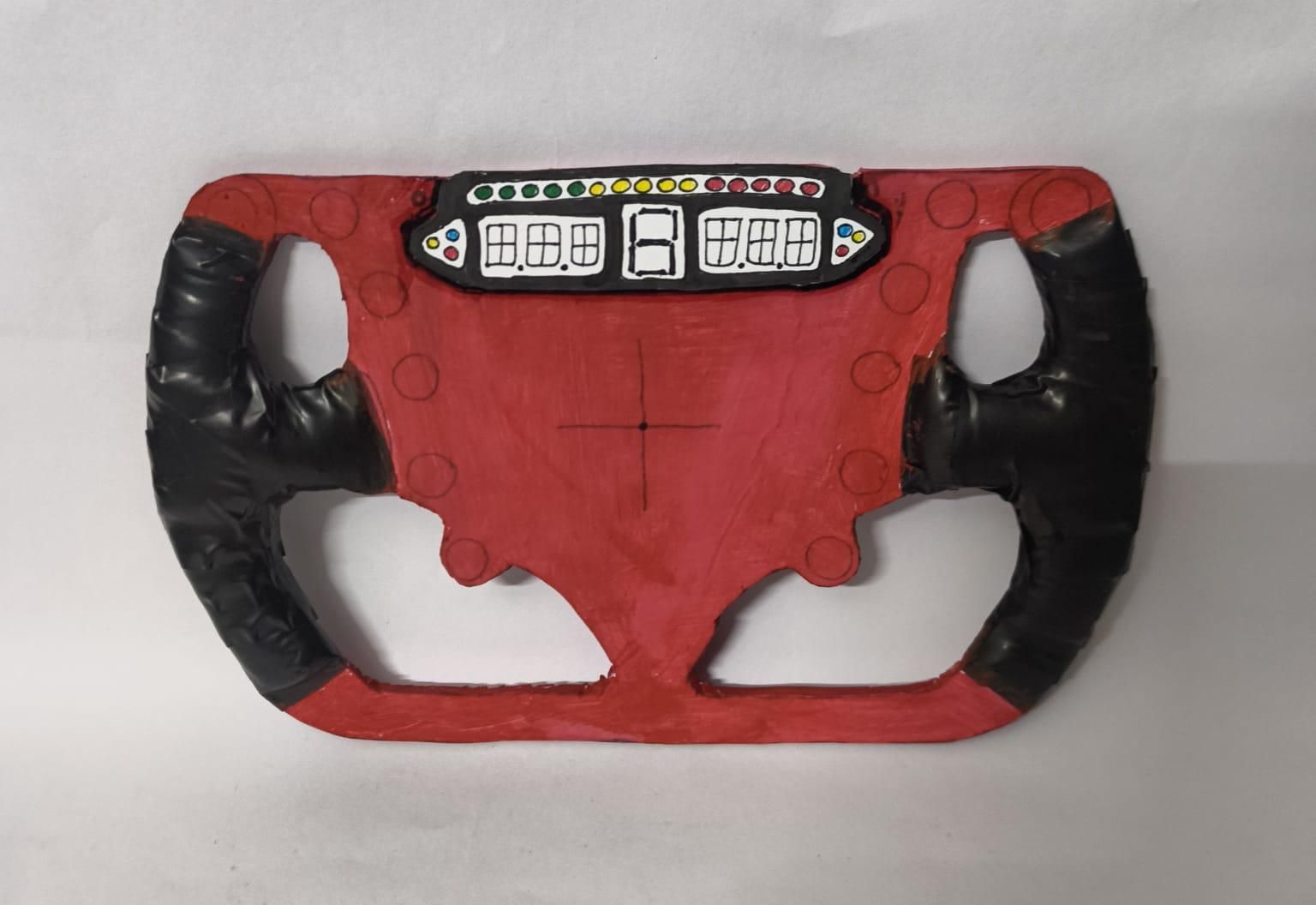
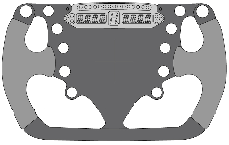
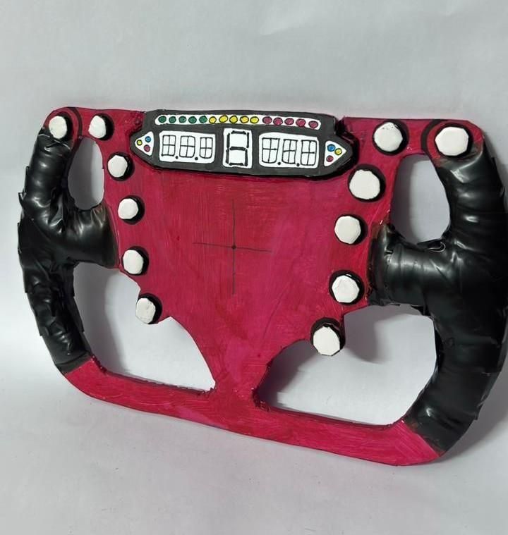
The steering wheel is the most visible part of this project, so feel free to spend some extra time making it look exactly how you want. I have provided a template for the wheel that I used, but you can also create your own design if you prefer.
Start by tracing the template onto a piece of 5 mm sunboard and carefully cut it out using a sharp cutter. Take your time with this step, especially around the corners and cutouts, as clean edges will make the final wheel look much more professional.
After cutting out the main shape, mark the exact center of the wheel. This is important because we will later make a hole here for mounting the steering shaft. Make sure the center is accurately marked to ensure smooth steering and proper alignment.
To give the wheel a realistic Formula-style appearance, I added a dashboard panel at the top and decorative buttons around the front. These details are optional, but they significantly improve the overall look of the project. You can create these parts from small pieces of foam sheet, cardboard, or sunboard and glue them in place.
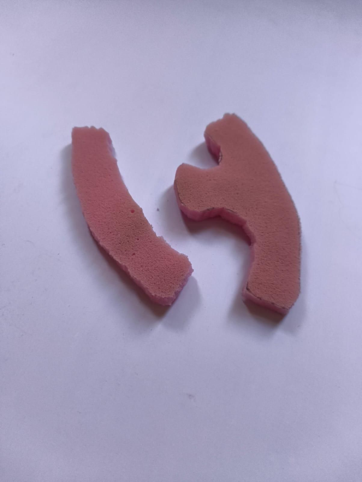
For a more comfortable grip, I wrapped the handles with foam and covered them with black tape. This enhances the immersion of racing games and makes the wheel feel much better in your hands. I have also included a short video showing the process of adding the foam grip. The video should make the construction process much easier to follow.
Once the construction is complete, paint the wheel in your favorite color scheme. I chose a Ferrari-inspired red and black theme, but you can customize it however you like. Add logos, racing numbers, button labels, or any other details that match your style.
When finished, allow the paint and glue to dry completely before moving on to the next step.
Downloads
Preparing the Pedals
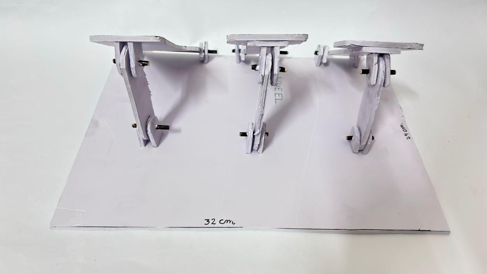
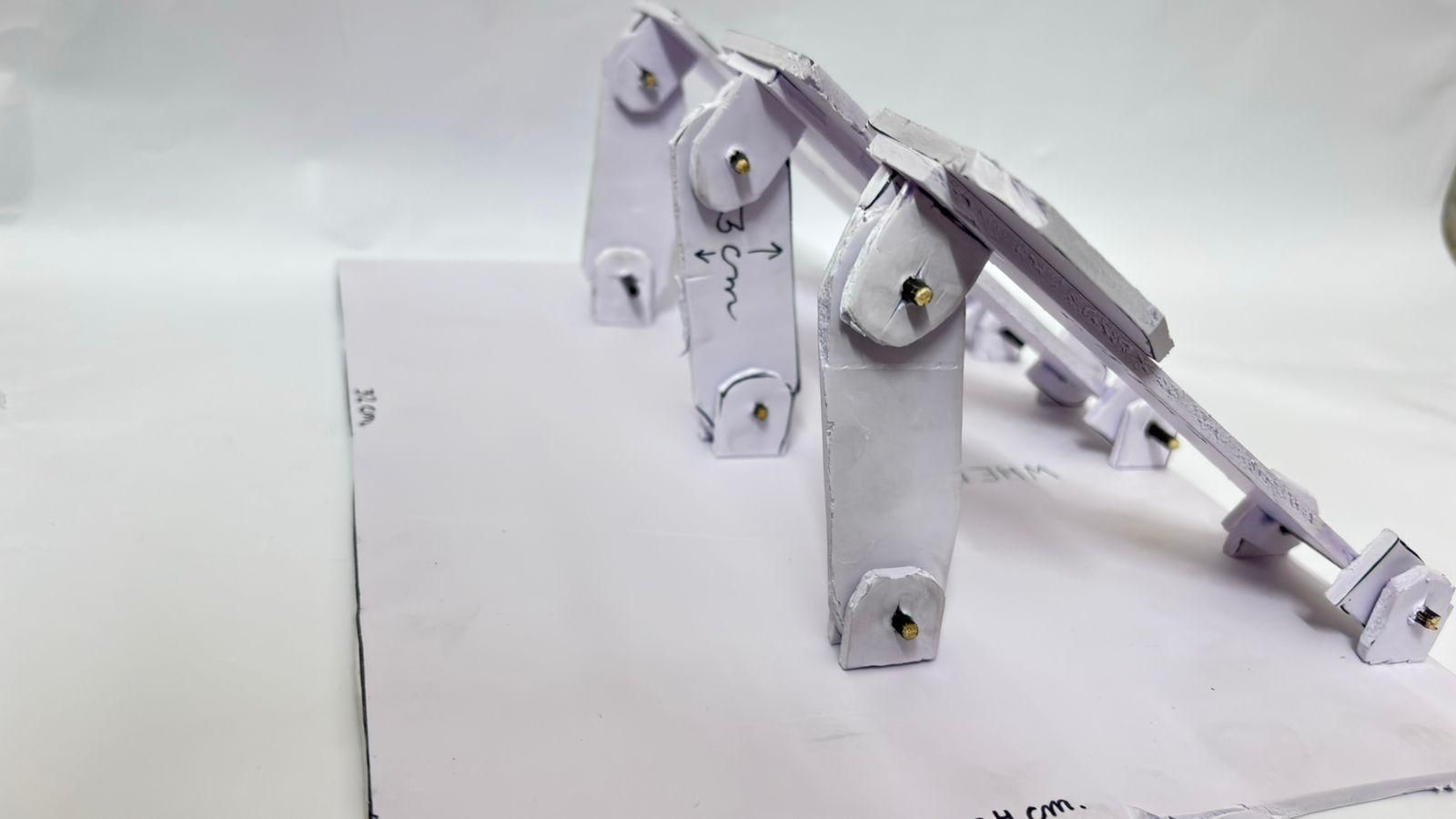
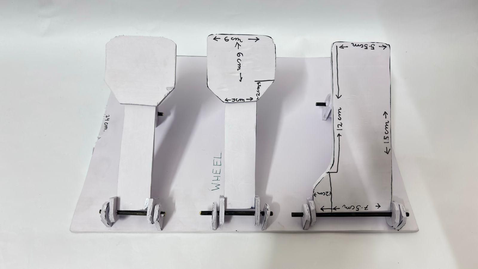
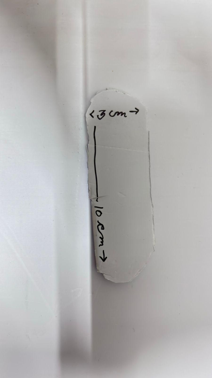
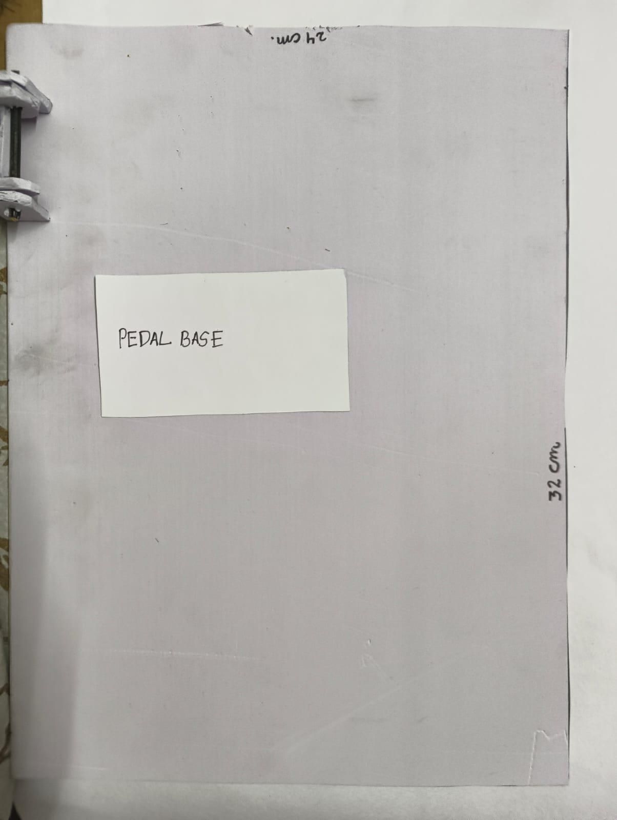
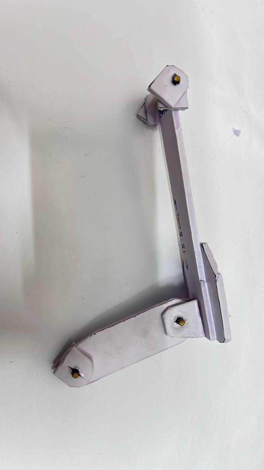
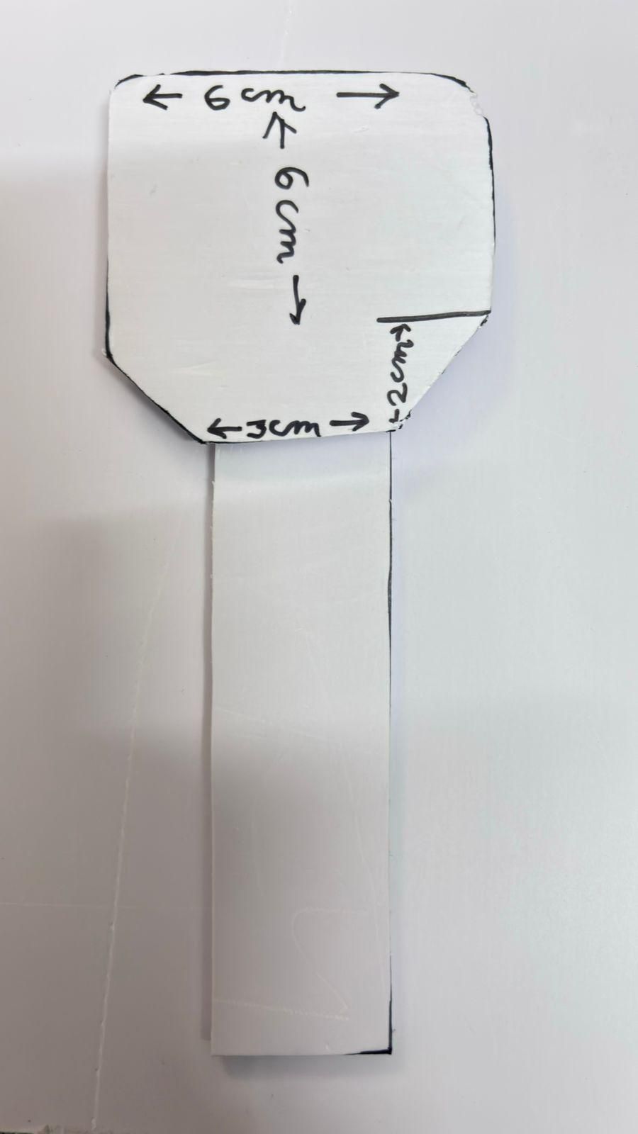
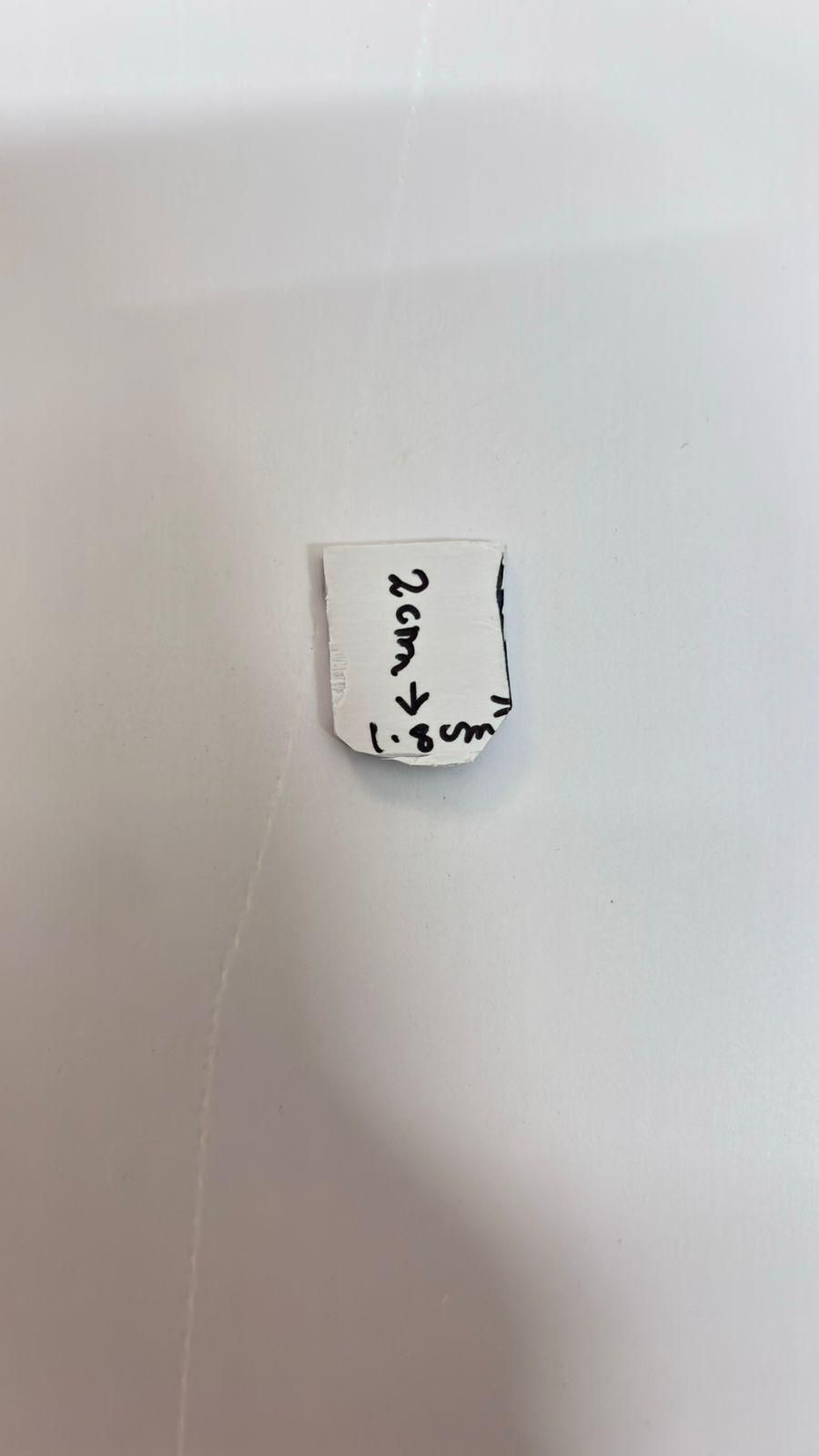
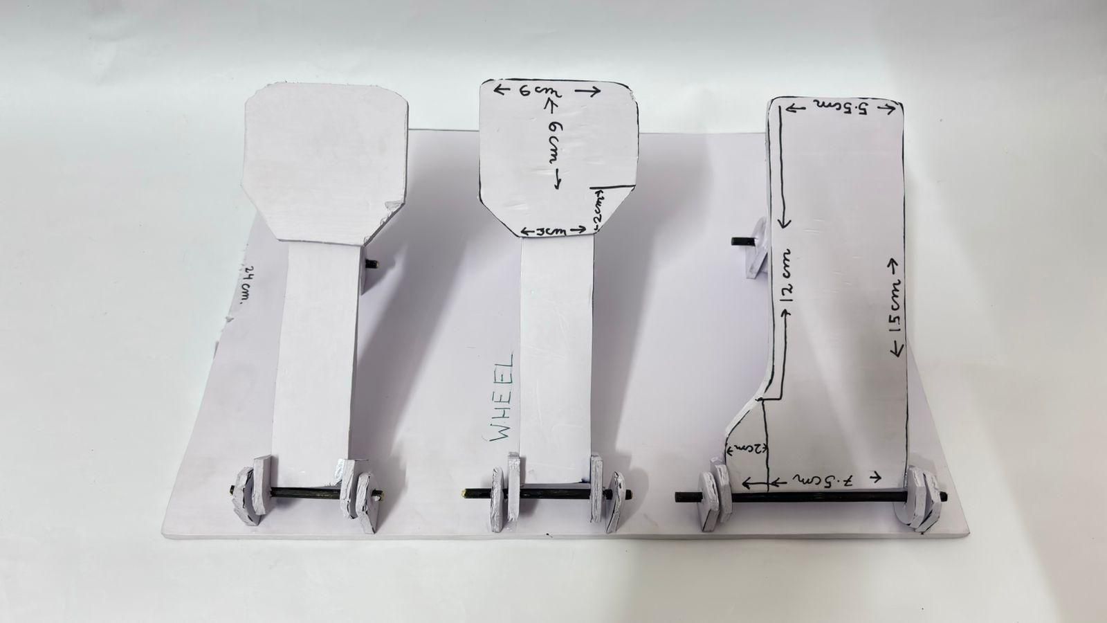
In this step, we will build the accelerator, brake, and clutch pedals. I have included templates for all the required parts, so simply cut each piece according to the dimensions shown.
Before assembling the pedals, cut a 24 cm × 32 cm piece of 5 mm sunboard. This will serve as the pedal base, on which all three pedals and the linkage mechanism will be mounted. Keep this base aside until the pedals are ready to be installed.
Start by cutting the pedal shapes from 5 mm sunboard using the templates. Cut one accelerator pedal and two copies of the smaller pedal, as these will be used for the brake and the clutch.
Since the brake and clutch pedals are shorter than the accelerator, cut two strips of sunboard according to the template and glue one to the bottom of each pedal. This will make all three pedals the same overall length and give the pedal set a cleaner appearance.
Making the Hinges
Each pedal pivots on a simple homemade hinge.
For each pedal, cut four of the small hinge pieces shown in the template.
- Make the center hole in two of the hinge pieces just large enough for a toothpick to fit tightly.
- Make the center hole in the other two pieces slightly larger so they can rotate freely around the toothpick.
Glue the two pieces with the larger holes directly onto the bottom of the pedal. Then slide a toothpick through them and attach the two pieces with the smaller holes to the sides. This creates a strong hinge while allowing the pedal to rotate smoothly.
Repeat these steps for the brake and clutch pedals until all three pedals have working hinges.
Making the Potentiometer Linkage
Now build the linkage that will connect each pedal to its potentiometer. Cut all the parts exactly as shown in the template.
You will also need four additional hinge pieces for each linkage. Make the holes in all four hinge pieces just large enough for a toothpick to fit tightly. The holes in the linkage arm itself should be slightly larger so that it can slide freely on the toothpick.
As the pedal is pressed, the linkage will move forward and push the potentiometer shaft. When the pedal returns to its original position, the linkage will also slide back, allowing the potentiometer to return smoothly.
Repeat this process for the accelerator, brake, and clutch so that each pedal has its own linkage mechanism.
Once completed, all three pedals should pivot freely and their linkages should slide smoothly. In the next step, we will mount them onto the 24 cm × 32 cm pedal base and connect them to the potentiometers.
Uploading the Code on ESP32
Now it's time to upload the code to the ESP32. This code reads the steering wheel, pedals, and paddle shifters, then sends the inputs to your computer as a Bluetooth game controller.
1. Install the Arduino IDE
If you don't already have it installed, download and install the latest version of the Arduino IDE.
2. Install the ESP32 Board Package
- Open Arduino IDE.
- Go to File → Preferences.
- In the Additional Boards Manager URLs box, paste the following URL:
- Click OK.
- Go to Tools → Board → Boards Manager.
- Search for ESP32 by Espressif Systems.
- Click Install.
3. Install the Required Library
This project uses the BleGamepad library.
- Go to Sketch → Include Library → Manage Libraries.
- Search for BleGamepad and NimBLE-Arduino.
- Install the latest version of both libraries.
4. Open the Code
You have two options:
- Option 1: Download and open the attached DIY_Racing_Simulator.ino file.
- Option 2: Copy the source code provided above and paste it into a new Arduino sketch. Save the sketch as DIY_Racing_Simulator.ino.
5. Connect the ESP32
Connect your DOIT ESP32 DEVKIT V1 to your computer using a data-capable Micro USB cable.
6. Select the Correct Board
In the Arduino IDE:
- Go to Tools → Board → ESP32 Arduino.
- Select DOIT ESP32 DEVKIT V1.
7. Select the COM Port
Go to Tools → Port and select the COM port corresponding to your ESP32.
8. Upload the Code
Click the Upload button (→) and wait for the code to compile and upload.
If your ESP32 doesn't upload automatically, hold the BOOT button while the upload starts and release it once the upload begins.
Downloads
Wiring the Pedals
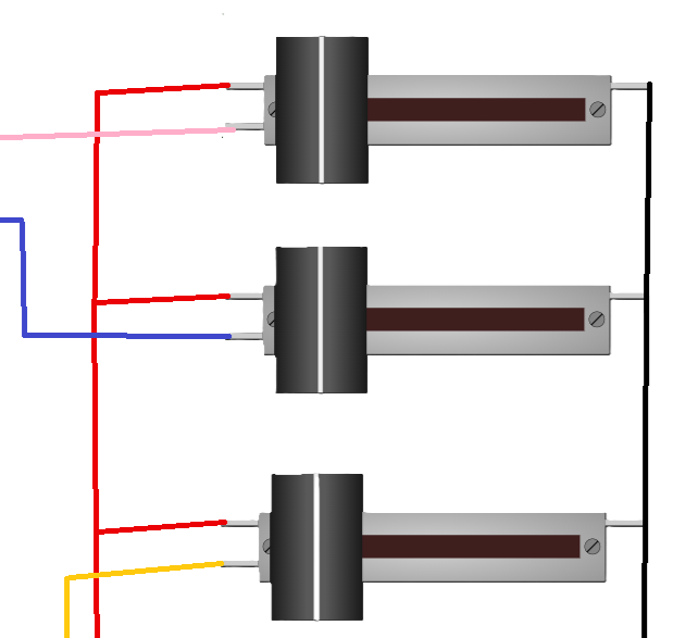
Now it's time to wire the three pedal potentiometers. In this step, we will only wire the pedals. The remaining wiring to the ESP32 and the other components will be completed after everything has been installed.
Refer to the wiring schematic provided with this step while making the connections.
Prepare the Potentiometers
Each pedal uses one linear potentiometer. Before mounting them, solder wires to each potentiometer to make the final installation much easier.
Create the Power Rails
Connect Pin 1 of all three potentiometers together. This will form the VCC rail.
Next, connect Pin 3 of all three potentiometers together. This will form the GND rail.
To supply power from the ESP32, solder approximately 1 meter of wire to Pin 1 of any one of the potentiometers. This wire will later be connected to the 3.3 V pin of the ESP32.
Similarly, solder another 1 meter wire to Pin 3 of any one of the potentiometers. This wire will later be connected to the GND pin of the ESP32.
Connect the Signal Wires
The center pin (Pin 2) of each potentiometer is the signal output.
Solder a separate 1 meter wire to Pin 2 of each potentiometer. These three wires will later be connected to the corresponding analog input pins on the ESP32.
Keeping the signal wires separate allows the ESP32 to read the position of the accelerator, brake, and clutch independently.
Check Your Connections
Before moving on, compare your wiring with the schematic diagram and ensure that:
- All Pin 1 connections are linked together.
- All Pin 3 connections are linked together.
- Each Pin 2 has its own separate signal wire.
- All solder joints are secure and insulated where necessary.
At this stage, do not connect the wires to the ESP32 yet. We will complete all of the final electrical connections after the pedals and steering assembly have been fully installed.
Build the Steering Assembly
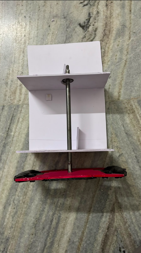
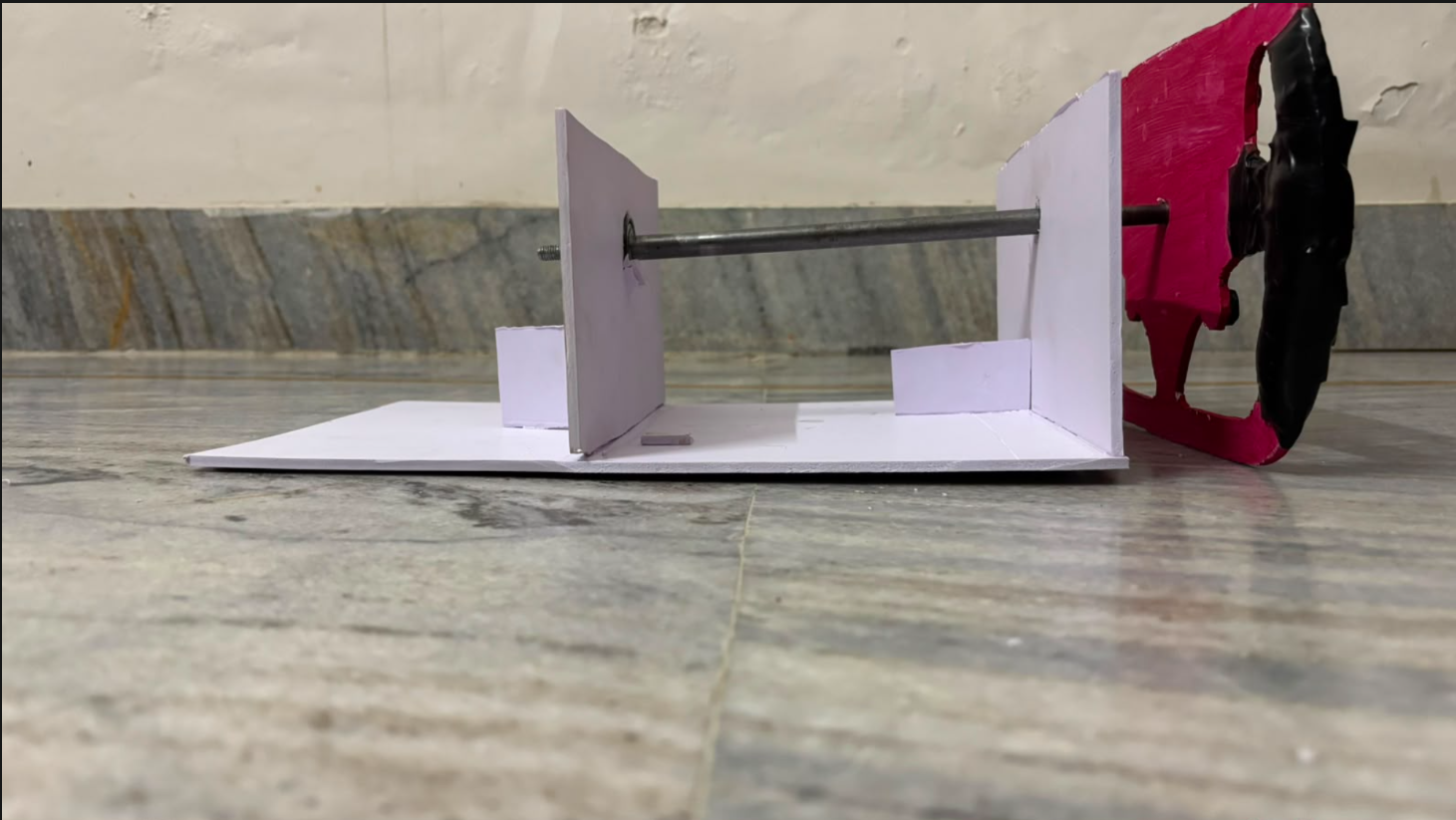
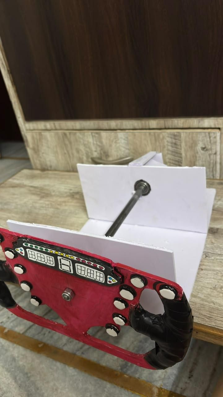
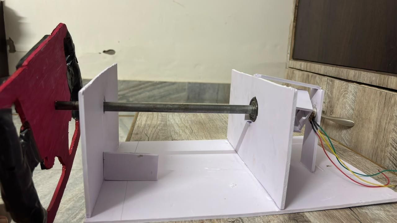
In this step, we will build the frame that supports the steering wheel, axle, and bearing. This assembly keeps the steering wheel aligned and provides enough space to mount the electronics behind it.
Cut the Base
Start by cutting a rectangle from 5 mm sunboard measuring 36 cm × 25 cm. This will serve as the main base of the steering assembly.
Next, cut two more rectangles, each measuring 13 cm × 25 cm. These pieces will act as the side supports for the steering axle.
Prepare the Side Supports
Find the center of each 13 cm × 25 cm rectangle and mark it carefully.
On one of the support pieces, cut a hole that matches the diameter of the steering axle (rod). Make this hole slightly larger than the rod so that it can rotate freely without rubbing against the sunboard.
On the second support piece, cut a hole to match the outer diameter of the bearing you are using. The bearing should fit tightly into this hole without any glue or movement. If you are not using a bearing, simply cut another hole the size of the steering axle, again making it slightly larger so the axle can rotate freely.
Assemble the Frame
Glue the two support pieces onto the 36 cm × 25 cm base as shown in the reference images.
- Position the first support piece flush with one edge of the base.
- Position the second support piece 15 cm away from the opposite edge of the base. This leaves enough space behind the support for mounting the ESP32, wiring, battery, and other electronic components.
Before the glue dries, check that both support pieces are perfectly aligned with each other. This is important to ensure that the steering axle passes through smoothly without binding.
Once the glue has fully cured, insert the axle through the holes (or through the bearing, if you are using one) and verify that it rotates freely. If necessary, slightly enlarge the axle hole until the steering shaft moves smoothly without excessive play.
Install the Steering Potentiometer
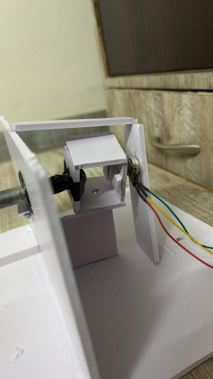
Now it's time to connect the steering potentiometer to the steering axle. This mechanism transfers the rotation of the steering wheel directly to the potentiometer, allowing the ESP32 to accurately detect the steering position.
Make the Coupler
Cut five or six small 2 cm × 2 cm squares from 5 mm sunboard.
These squares will be stacked together to create a strong coupler between the steering axle and the potentiometer shaft.
Take two or three of the squares and make a hole in the center that matches the diameter of the potentiometer shaft. The potentiometer should fit tightly inside these pieces.
In the remaining two or three squares, make a hole that matches the diameter of the steering axle. The axle should also fit snugly without any movement.
Stack all of the pieces together as shown in the reference images, making sure the axle and potentiometer holes are perfectly aligned. Once you are satisfied with the fit, glue the pieces together using hot glue, Fevikwik, or any strong adhesive that creates a rigid connection.
The finished coupler should firmly connect the steering axle to the potentiometer so that both rotate together without slipping.
Mount the Potentiometer
Next, position the potentiometer underneath the steering axle.
The potentiometer shaft must be exactly level with the steering axle so that the coupler fits straight without putting any stress on either shaft.
Use pieces of sunboard as spacers to raise the potentiometer to the correct height. Once everything is properly aligned, glue the potentiometer securely in place. Refer to the images for the exact placement and support arrangement.
Important
Do not attach the steering wheel to the axle yet.
Leaving the steering wheel off at this stage makes it much easier to calibrate the potentiometer and set the steering wheel to its center (0°) position later. Once the electronics are tested and the steering is correctly centered, the steering wheel can be installed in its final position.
Before moving to the next step, rotate the axle by hand to ensure that the potentiometer turns smoothly throughout its range without binding or slipping. If necessary, make small adjustments to the coupler before the glue fully cures.
Make the Paddle Shifter
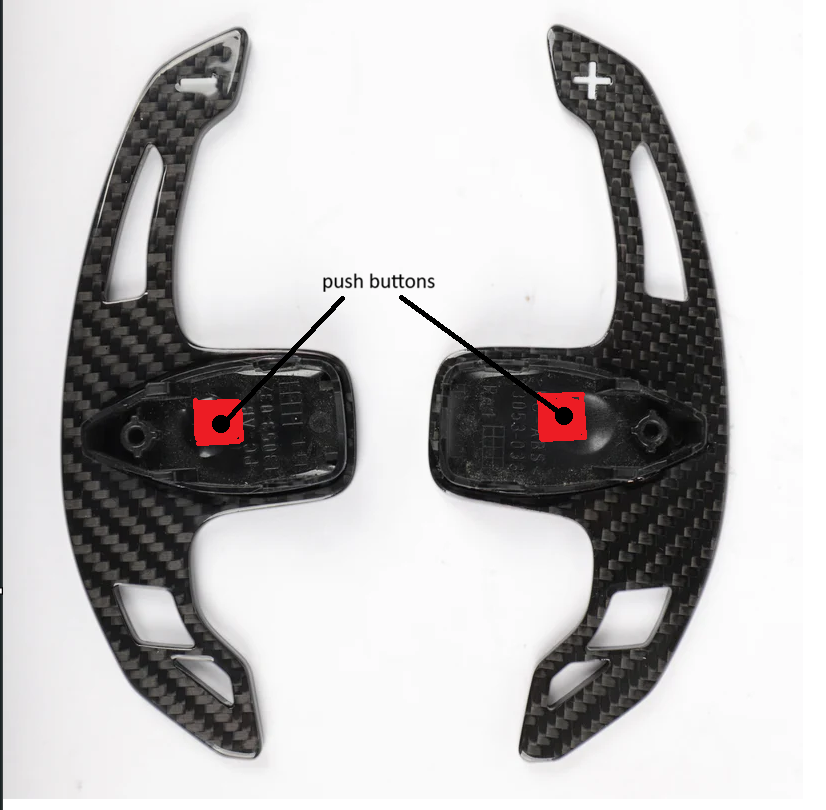
In this step, we will build the paddle shifters that will be used for shifting gears in your racing games.
Make the Paddle Shifters
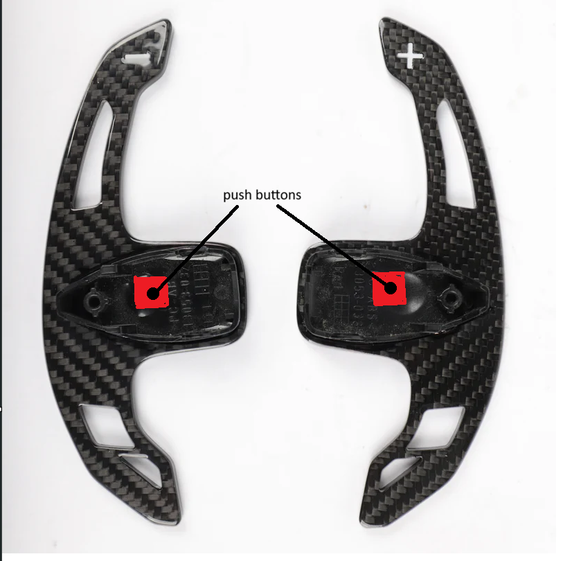
Begin by cutting two paddle shifters from 5 mm sunboard. You can use any shape or design you like, depending on your preference. One paddle will be used for Shift Up, and the other for Shift Down.
Once the paddle shifters have been cut out, mark the position where the push button will be mounted. Carefully cut a hole in the center of each paddle shifter that matches the size of your push button. The button should fit snugly into the opening.
Insert the push button into the hole and secure it using hot glue or another strong adhesive. Make sure the button remains firmly in place while still being easy to press.
Wire the Push Buttons
Solder two wires to each push button.
To prevent the wires from becoming tight or tangled while the steering wheel rotates, leave one long loop of wire between the paddle shifters and the electronics. This extra length allows the steering wheel to turn freely without putting stress on the wires.
Route the Wires
In the front support panel where the steering wheel shaft passes through, drill or cut four small holes. These holes will be used to route the wires from both paddle shifters to the electronics compartment.
Pass all four wires through these holes and into the electronics compartment. Leave enough slack outside the enclosure so the steering wheel can rotate comfortably without pulling on the wires.
Connect the Circuit
Once the wires have been routed, connect the paddle shifters according to the wiring diagram provided with this project.
Double-check that all solder joints are secure before moving on to the next step.
Mount the Paddle Shifters
Finally, attach the paddle shifters to the back of the steering wheel.
Apply glue only to the end of each paddle shifter, as shown in the reference images, and press them firmly into position. Avoid applying glue near the section that flexes when the button is pressed, as this could reduce the movement of the paddle.
After the glue has cured, test both paddle shifters to ensure they move freely, press the buttons reliably, and do not interfere with the steering wheel while turning.
Install the Linear Potentiometers
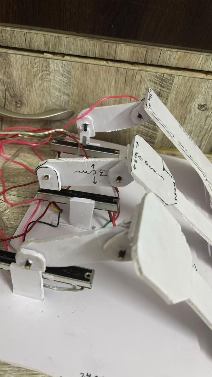
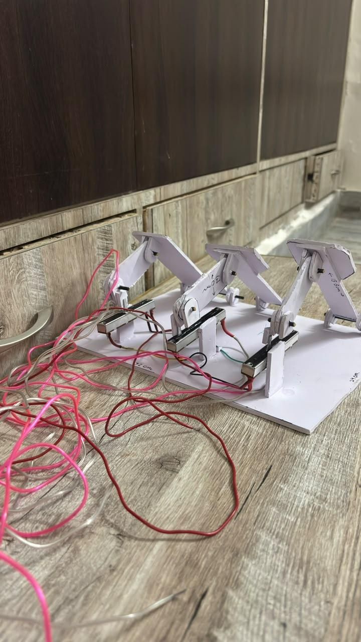
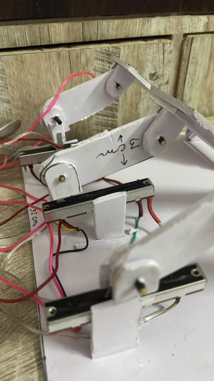
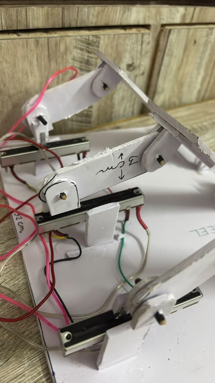
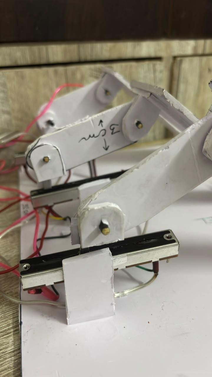
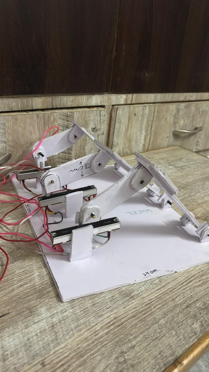
In this step, we will install the three linear potentiometers and connect them to the pedal linkage. This mechanism converts the movement of each pedal into a linear motion that the ESP32 can accurately read.
Mount the Linear Potentiometers
Position one linear potentiometer for each pedal. You can mount them at any height that suits your design, as long as the linkage can travel through its full range of motion without binding or putting stress on the potentiometer.
I recommend mounting the potentiometers directly onto the pedal base, near the rear of the assembly. This keeps the mechanism simple, compact, and easy to align.
Before fixing them permanently, move each pedal by hand and ensure that the linkage can push and pull the potentiometer smoothly throughout its entire travel.
Connect the Linkage
At the free end of each linkage arm, glue a small piece of sunboard that can be attached securely to the moving rod of the linear potentiometer. This connection allows the potentiometer rod to move whenever the pedal is pressed.
When the pedal is pushed forward, the linkage should smoothly pull or push the potentiometer rod through its full travel. Likewise, when the pedal returns to its resting position, the potentiometer rod should also return to its original position.
Repeat this process for the accelerator, brake, and clutch pedals until all three potentiometers are connected.
Install the Return Springs
To make the pedals return automatically after being pressed, install a compression spring behind each pedal.
Position each spring between the bottom of the pedal and the pedal base, as shown in the reference images. The spring should compress when the pedal is pressed and expand when it is released, returning the pedal to its starting position.
Adjust the spring position if necessary to ensure smooth pedal movement and consistent resistance. All three pedals should move freely and return to their original positions without sticking.
Final Check
Once everything has been installed, press each pedal several times to verify that:
- The pedal moves smoothly throughout its full range.
- The linkage moves freely without binding.
- The linear potentiometer reaches its full travel without being forced beyond its limits.
- The return spring brings the pedal back to its original position every time.
After completing this step, the pedal assembly is mechanically finished and ready to be connected to the rest of the electronics.
Making the Circuit
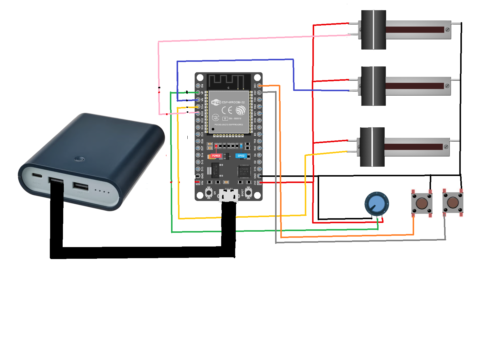
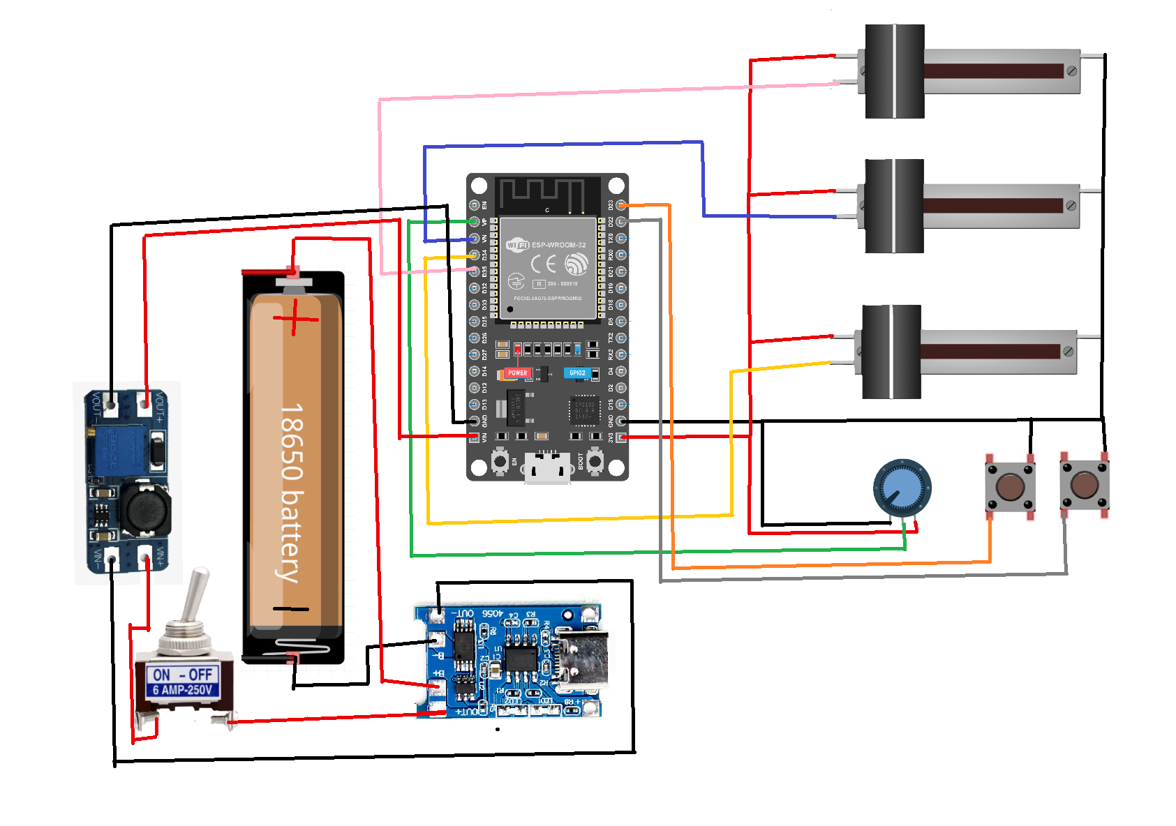
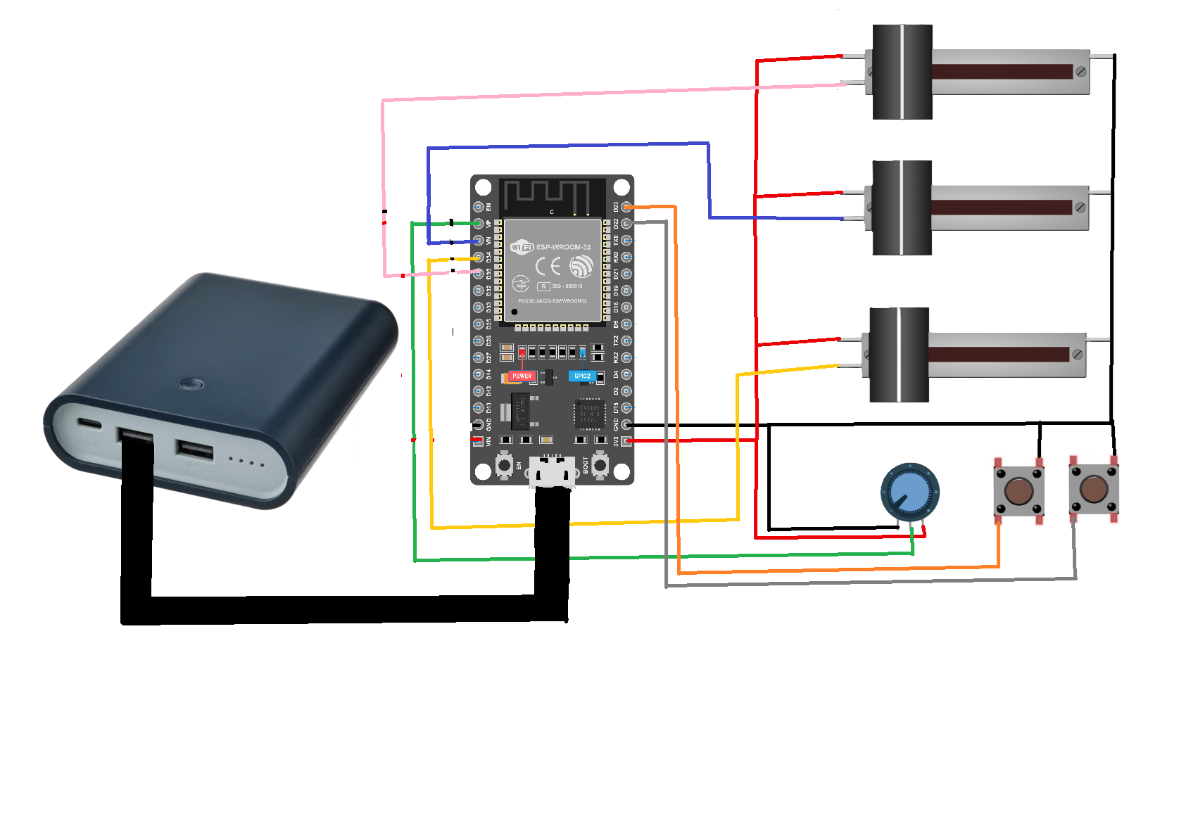
Now that all the mechanical parts have been assembled, it's time to wire the electronics together. Before soldering any wires, place all the electronic components in their final positions. This will help you determine the required wire lengths and keep the wiring neat and organized.
Refer to the wiring diagram provided with this step and make all the connections exactly as shown.
Mount All Electronics First
Before making any electrical connections, temporarily place the following components in their final locations:
- ESP32 DOIT DevKit
- Steering potentiometer
- Three linear potentiometers
- Two push buttons (paddle shifters)
- Power source
Once you are satisfied with the placement, begin wiring the components.
Create VCC and GND Rails
To simplify the wiring, create two common power rails.
- Connect all 3.3 V (VCC) connections together to form a VCC rail.
- Connect all Ground (GND) connections together to form a GND rail.
Using common power rails keeps the wiring clean and makes troubleshooting much easier.
Connect the Signal Wires
Connect each signal wire to its corresponding ESP32 pin according to the wiring diagram.
Double-check every connection before applying power.
Solder All Connections
Although you can temporarily test the circuit using jumper wires, I highly recommend soldering every connection once everything is working correctly.
Soldered connections are much more reliable than loose jumper wires and help reduce electrical noise and intermittent signal issues caused by vibration or poor contact.
Powering the Simulator
I powered my simulator using a USB power bank, as it is simple, portable, and easy to recharge.
One important thing to note is that your power bank must not have an automatic low-power shutdown feature. Some power banks automatically turn off when the current draw is too low, which can cause the ESP32 to shut down unexpectedly.
Optional Rechargeable Battery
If you would like to build a completely self-contained system, you can power it using a single 18650 Li-ion battery, a TP4056 charging module, and an MT3608 boost converter.
Make the connections as follows:
This configuration allows you to recharge the battery through the TP4056 module while supplying a stable 5 V output to the ESP32.
Final Inspection
Before powering the circuit for the first time, check that:
- Every VCC connection is connected to the VCC rail.
- Every GND connection is connected to the GND rail.
- All signal wires are connected to the correct ESP32 pins.
- There are no short circuits or loose solder joints.
- All wires are neatly routed and secured.
Once everything has been checked, power on the ESP32 and verify that the steering wheel, pedals, and paddle shifters are all detected correctly by your computer.
Pair the Controller and Configure Your Game
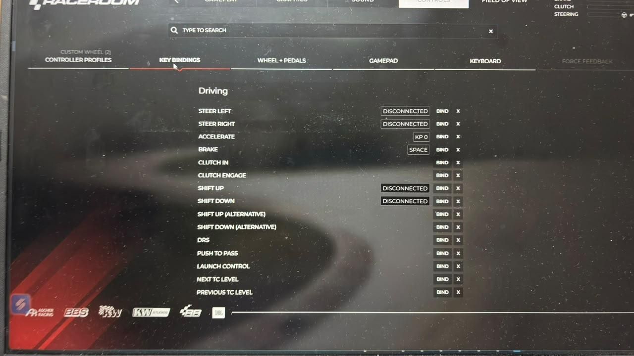
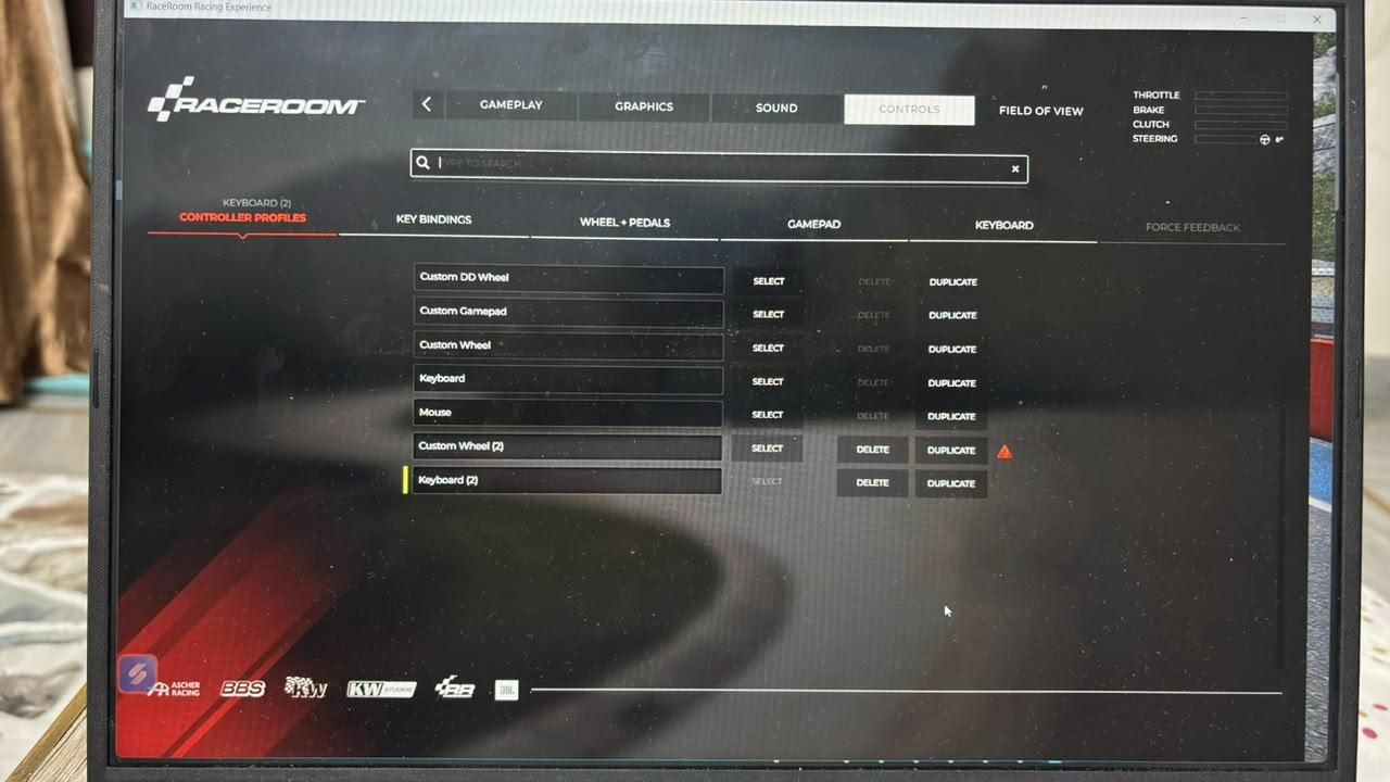
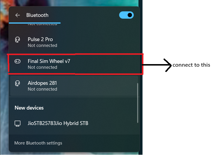
Now that your racing simulator is complete, it's time to connect it to your computer and configure it for your favorite racing game.
Pair the ESP32
- Turn on Bluetooth on your computer.
- Open Bluetooth & Devices in the Windows Settings.
- Click Add Device and select Bluetooth.
- Wait for Final Sim Wheel v7 to appear in the list of available devices.
- Select it and click Pair.
Once paired successfully, Windows will recognize it as a Bluetooth game controller.
Configure the Controls
Open the racing game you want to play. As an example, I will use RaceRoom Racing Experience.
- Launch the game.
- Go to Settings → Controller Options.
- Select Custom Wheel as your controller profile.
- Open the Controller Settings or Control Bindings menu.
Now bind each control one by one.
- Click Bind for the Steering control, then rotate the steering wheel.
- Click Bind for the Accelerator, then press the accelerator pedal.
- Click Bind for the Brake, then press the brake pedal.
- Click Bind for the Clutch, then press the clutch pedal.
- Click Bind for Shift Up, then press the right paddle shifter.
- Click Bind for Shift Down, then press the left paddle shifter.
Repeat this process until every control has been assigned correctly.
Start Racing
Once all the controls have been configured, save your controller profile and start a race. If any control behaves incorrectly, simply return to the controller settings and recalibrate or rebind that control.
Customize Your Racing Simulator
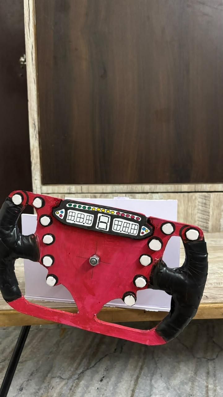
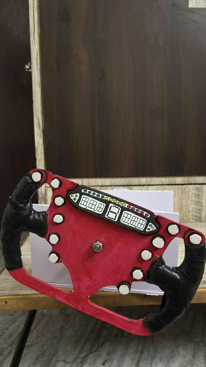
Congratulations on completing your DIY racing simulator! Now it's time to make it truly your own.
Feel free to paint the simulator in any color scheme you like. Whether you want a Ferrari-inspired red, a Mercedes-AMG Petronas silver and black, a McLaren orange, a Red Bull Racing blue, or your own unique design, the choice is entirely yours.
You can also personalize your simulator by adding:
- Racing decals and stickers
- Team logos
- Button labels
- Carbon-fiber vinyl wrap
- Colored accents
- LED lighting (optional)
These finishing touches can make your simulator look much more realistic and give it a professional appearance.
Feedback and Future Improvements
This project is still evolving, and I would love to continue improving it with your help.
If you have any suggestions, ideas, or improvements, please leave them in the comments. I'm always open to feedback and would love to hear how you built or customized your own version.
One of my biggest goals for future versions of this project is to add force feedback to make the driving experience even more immersive. If you have experience with force feedback systems or have ideas on how to implement them, I would greatly appreciate your suggestions.
If you build this project, don't forget to share a photo of your finished simulator. I'd love to see the different designs and customizations everyone comes up with.
Finally, if you run into any problems while building the project, feel free to leave a comment. I'll do my best to help you troubleshoot the issue and get your simulator up and running.
Thank you for following this Instructable, and happy racing! 🏁
If you enjoyed this project, please leave a Like and share this Instructable with anyone who would enjoy building their own DIY racing simulator. Your support means a lot to me and encourages me to keep creating and improving projects like this.