Backyard Ambient Comfort & Safety Station
by Crazy_ Whale in Circuits > Electronics
210 Views, 3 Favorites, 0 Comments
Backyard Ambient Comfort & Safety Station
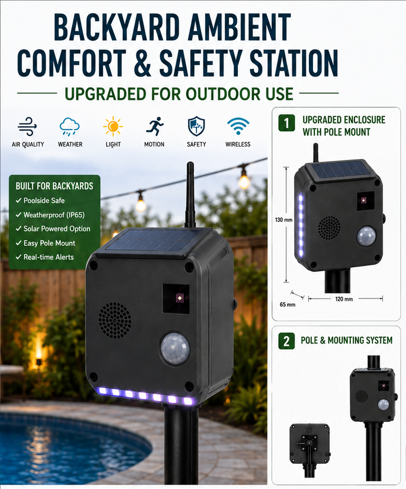
This project builds a weatherproof sensor pod that mounts on a patio post or fence and continuously monitors your backyard's temperature, humidity, air quality, UV index, and motion. It reacts locally with color-shifting LED lighting and sounds an alarm on poor air quality, and it reports everything live to your phone through the Blynk IoT app, with push notifications when conditions cross a safety threshold.
It fits a Backyard Contest brief perfectly: it's practical (safety monitoring near a grill or fire pit), playful (reactive ambient lighting), and it brings people outside by making the space feel alive and responsive. The 3D-printed enclosure design also makes it a strong candidate for an Autodesk-software design award.
What you'll build
- A weatherproof ESP32 sensor pod with BME280, MQ135, UV sensor, and PIR motion sensor
- A WS2812 LED strip that changes color based on live conditions
- A buzzer and push-notification alert system for smoke/poor air quality and high UV
- A live mobile dashboard in the Blynk IoT app showing every sensor reading
- A custom 3D-printable enclosure designed in OpenSCAD/Fusion 360
Supplies

Hardware needed for this build:
Component Qty
ESP32 DevKit V1 (30-pin) 1
BME280 module (I2C) 1
MQ135 gas sensor 1
GUVA-S12SD UV sensor 1
HC-SR501 PIR motion sensor 1
WS2812B LED strip (1m) 1
Active buzzer module 1
5V 3A power adapter 1
Logic-level MOSFET / level shifter 1
470 ohm resistor + 1000uF capacitor 1 each
IP65 weatherproof enclosure (or 3D printed) 1
Cable glands 3-4
Perfboard 1
Mounting brackets/U-bolts 1 set
Software needed:
- Arduino IDE with ESP32 board package installed
- Blynk library, Adafruit BME280 library, Adafruit Unified Sensor library, Adafruit NeoPixel library
- OpenSCAD (free) for the 3D enclosure model, or Fusion 360 if recreating it parametrically there
- A free Blynk.Cloud account and the Blynk IoT mobile app
Design and Print the Enclosure
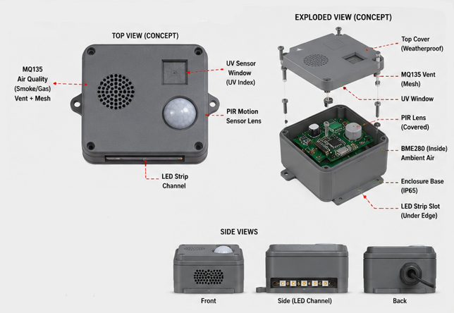
The enclosure is a 160 x 120 x 70mm weatherproof box with a PIR dome cutout and UV sensor window on the front face, stacked vent slots on the side for the MQ135 to breathe, a groove along the bottom edge for the LED strip, a cable gland hole in the bottom, and a rear mounting bracket with two screw holes.
Model this in OpenSCAD (a parametric script makes it easy to resize) or recreate the same dimensions in Fusion 360 if you want the full CAD history for the Autodesk Design & Make Award submission. Print the shell and lid separately, in a UV-resistant filament such as ASA or PETG since this part lives outdoors.
Once printed, test-fit each sensor in its cutout before final assembly, and lightly sand any tight-fitting holes.
Wire the Sensors to the ESP32
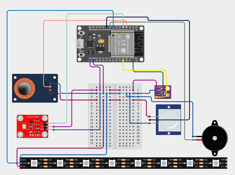
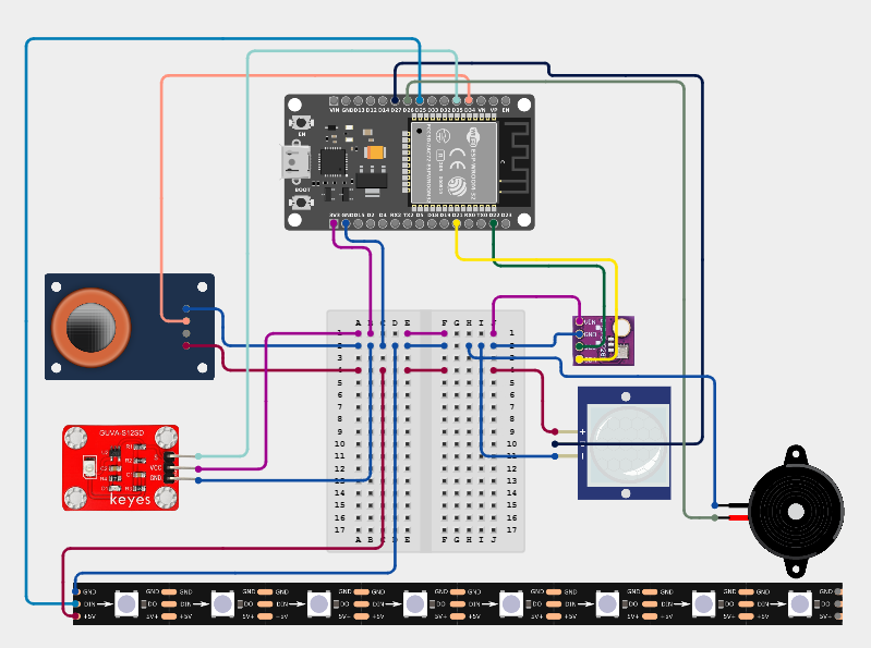
A few things to watch for while wiring:
- GPIO 34 and 35 are input-only on most ESP32 boards - fine here since both are analog sensor inputs
- The WS2812 data line needs the level shifter because the ESP32's 3.3V logic can cause flicker on 5V-expecting strips
- Power the MQ135 from 5V rather than 3.3V, since its heater draws more current than the 3.3V rail comfortably supplies
- Avoid GPIO 6 through 11 - these are reserved for the ESP32's internal flash
Assemble Everything Into the Enclosure
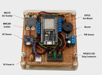
Solder your wiring onto perfboard for a secure, vibration-resistant connection, then mount the ESP32 and perfboard inside the printed enclosure. Route the LED strip along the bottom channel, seat the PIR and UV sensor in their front cutouts, and position the MQ135 near its vent slots so it has open airflow. Feed the power cable through a cable gland at the bottom, and seal every gland and cutout edge with a thin bead of silicone sealant once wiring is confirmed working.
Flash the Firmware
Open the Arduino IDE, install the ESP32 board package (via Boards Manager) and the required libraries (Blynk, Adafruit BME280, Adafruit Unified Sensor, Adafruit NeoPixel). Select Board: ESP32 Dev Module and the correct COM port.
The firmware reads all four sensors every 5 seconds, pushes the data to Blynk virtual pins, drives the LED strip's color based on live conditions, and fires a push notification plus local buzzer when air quality or UV crosses your threshold. Key logic:
Before uploading, fill in your Wi-Fi SSID/password and your Blynk Template ID and Auth Token (from Step 6 below).
Set Up the Blynk IoT App
1. Create a free account at blynk.cloud
2. Go to Templates > New Template, name it "Backyard Station", set hardware to ESP32 and connection type to WiFi, then save. Copy the generated Template ID and Template Name into your firmware code.
3. Inside the template, go to Datastreams > New Datastream > Virtual Pin, and create one for each sensor: Temperature (V0), Humidity (V1), Pressure (V2), Air quality (V3), UV index (V4), Motion (V5), LED manual override (V6), Alert log (V7).
4. Go to Events > New Event and create two events named air_quality_alert and uv_alert, enabling push notifications for each.
5. Go to the Web Dashboard tab and add widgets bound to each virtual pin: gauges for temperature/humidity/pressure/air quality/UV, a label for motion, a switch for the LED override, and a label for the alert log.
6. Go to Devices, create a new device from your template, and copy the generated Auth Token into your firmware code.
7. Download the Blynk IoT app (App Store or Google Play) and log in with the same account - your dashboard appears automatically once the ESP32 connects.
Mount Outdoors and Calibrate
Attach the enclosure to your patio post or fence using the mounting bracket, at a height that gives the PIR a good field of view and keeps the MQ135 near where you'd actually want smoke or air-quality detection, such as near a grill or fire pit.
Let the MQ135 burn in outdoors for 24 to 48 hours before trusting its readings. Log baseline values from the Blynk dashboard history over a few days, then adjust the AIR_QUALITY_ALERT_RAW and UV_ALERT_INDEX thresholds in the firmware to match realistic conditions for your specific yard.
Enjoy and Document
Once running, the LED strip will glow green under normal conditions, shift to blue when motion is detected, amber when it's hot or humid, orange for high UV, and red with a buzzer and push alert if air quality drops. Photograph the build stages, the enclosure CAD model, the wiring, and the finished mount outdoors, and capture a short video of the LEDs reacting to a triggered condition for your Instructables submission.
Notes and possible upgrades
- Add a rain sensor to trigger an automatic retraction or cover-check reminder
- Log historical data to a spreadsheet or database for seasonal comfort trend analysis
- Add a second LED zone to visually separate the safety alert color from the ambient mood color
Support
Support me: Crazy Whale - Buymeacoffee