Bluetooth Controlled Spider Robot That Shoots!
by MatijaHardi in Circuits > Robots
1627 Views, 17 Favorites, 0 Comments
Bluetooth Controlled Spider Robot That Shoots!


For a long time I've had this one "Spider Robot DIY Kit Super Fun For Kids" in box just collecting dust. I think I bought it for my little cousin a few years back and never gave it to him but I don't even remember. One day, bored out of my mind, I decided to assemble it for myself and was very quickly disappointed.
The kit itself is actually pretty good and the assembly instructions are not half bad but it is meant for ages eight and up so I (aged 20) didn't find it too amusing. As the robot in the original form has only two modes, on and off, I first came up with the idea to just connect the existing motor to an Arduino over an H-bridge and have it randomly go forwards and backwards but the more I thought about it the more things I imagined to make of it.
I came up with a rough idea on what I wanted the robot to do and through the design process I added some pretty cool features that I'm thrilled to present in this instructable.
Supplies


The first thing you need to upgrade a spider robot is the spider robot. I found this one on Amazon, I can't be sure if that's the same exact model as the one I had but based on the photos it's the same thing.
Also for the shooting functionality you're going to need something to shoot. This was a tricky one to hunt down but I found this toy gun which seems to contain the same dart I used. Again the same as the spider, I can't be sure that it's exactly the same thing but should be close enough to work. You have to buy the whole set with the gun, eyepatch and hook though :(
Just in case I included a CAD file of a dart based on mine so you can adjust it to your needs and make your own, don't forget the spring.
Materials/ Parts needed:
3D printed parts (models in Step 1)
Continuous rotation servo motor x2
Arduino Nano x1 (really any Arduino or board that fits will work)
Mosfet transistor x1 (any kind you have is fine, mine was an BDX54K NPN transistor)
A protoboard and some pins/headers
A USB cable or type A plug x1
A battery (I used a cheap single cell power bank I had)
Some ribbon cable
Tools I used:
3D printer
Soldering Iron
Screwdrivers, pliers, blades etc.
Note: if any descriptions in this Instructable are unclear feel free to consult my notes on the photos
Downloads
The Design and Printing of the Parts


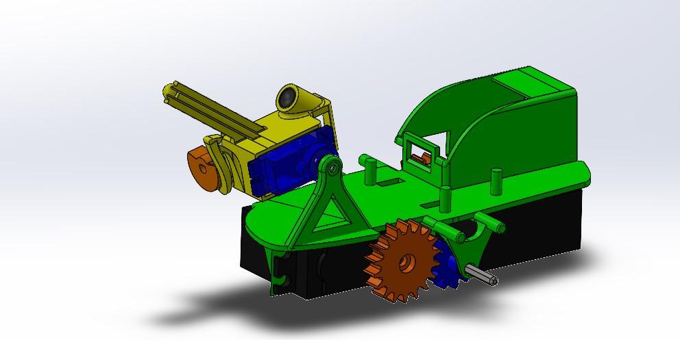
I firstly started on the body design as I needed to figure out all of my components placement in order to think about how I'm going to make it move. I went through five or six iterations but somehow I managed to get the part as I wanted it to be so I moved on to the other parts.
The gearing is a 3:2 reduction for faster walking. I decided to make a gear system because while the servo motors are strong and have a lot of torque they aren't very fast and I didn't want for it to take forever to move (and never catch anyone to shoot).
In the and I am very happy with the design because I managed to squeeze everything I wanted into the design without making it look like a complete mess.
Gearing Up


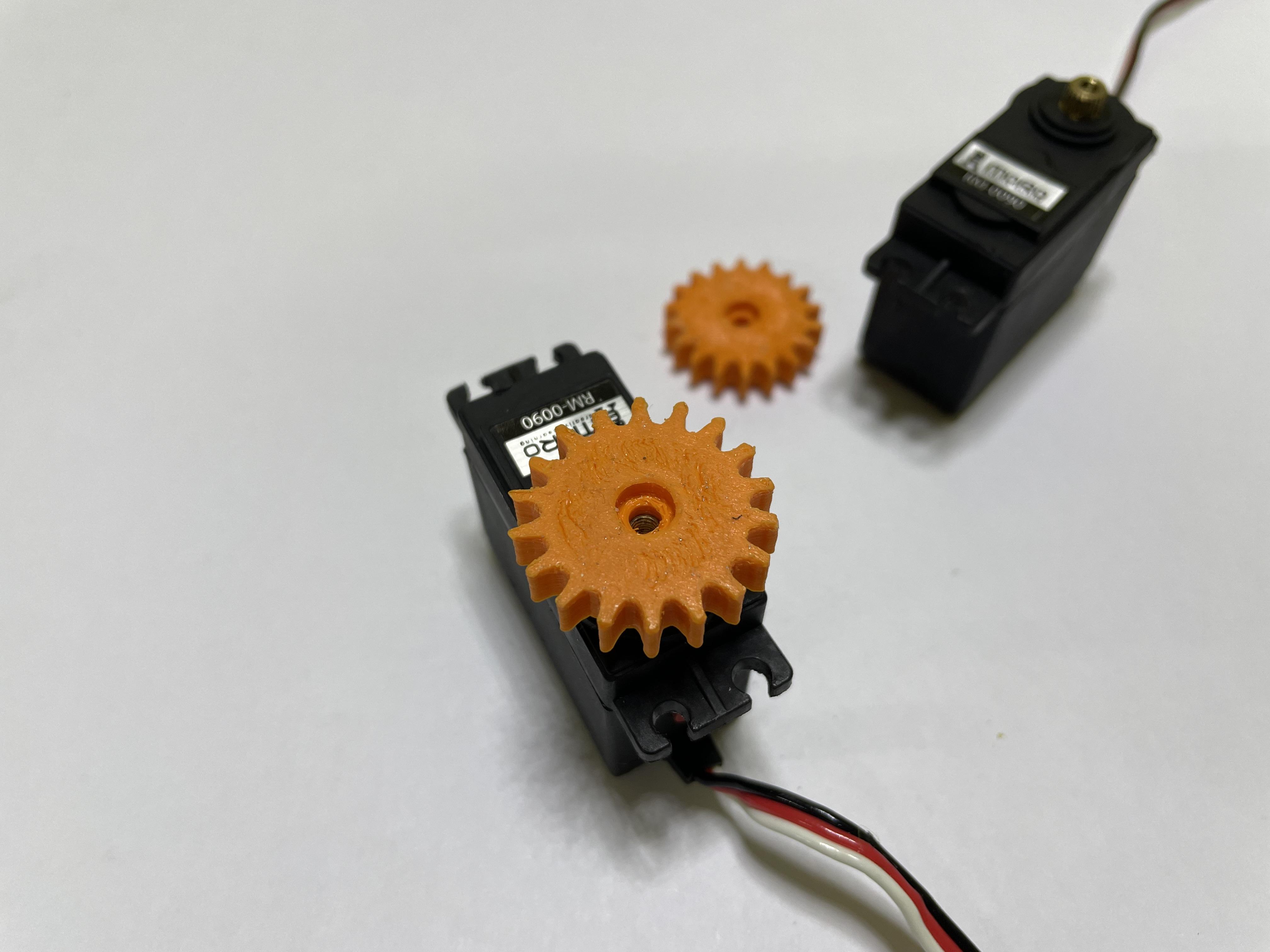
Once you have all the parts begin by attaching the gears to the motors. These two motors are propulsion motor and are responsible for moving the robot forwards.
Push the gear onto the servo (this might require a bit of gentle persuasion) and then secure it with a screw. Do this for both motors and you're done.
Note: some really cheap motors don't come with screws so you might have to source those yourself
Securing to the Body


Once you're all geared up you can attach the motors to the body. Begin by pulling the cables through the designated holes as it will be very tricky to do this afterwards. Once the cables are through the motors should pretty much just fall into place and you can secure them to the body using some screws. I drilled the stands using a 2mm drill bit and put two screws on opposite corners of the motor.
Do the same for both motors and you're done.
Getting the Axle


The original robot uses a simple DC motor with a reduction powered by a single AA battery to move its legs. The legs have their own gear mechanisms (which I didn't redo, I only made a new body driving the old legs) and the center gear is connected onto a hexagonal axle, I didn't want to make those gears new so I just used the original axle. Doing so meant that I first had to harvest it from the original motor. I pulled the axle out of the case with pliers and then cut it in half because you are now driving the left and right legs separately.
Note: while cutting the axle, try to make the cut as thin as possible because the new body adds about 20mm to the width so you might end up short
Assembling the Drivetrain


With the other gears and to axle halves you can finish the drivetrain. Begin by placing the smaller gear in the space available and make sure that it's centered so you don't have any problems when installing the axle.
Once lined up push the axle through the gear and make sure that it's in all the way.
Do this on the other side and you have a completed drivetrain.
The Board


Once all the mechanical bits are done you can move on to the electrical stuff. I cut my protoboard in an 'L' shape to save some space around the battery box on the body. You can make it into any shape you want as you can print the body without the battery box.
Figure out any layout of the components you want but make sure you don't have to make any difficult runs on your board. Once you have it figured out solder it in place using the schematic, the circuit is quite simple so you shouldn't have any issues.
I don't have the transistor or the capacitor in the photos because I added the transistor a bit later and you can see it in the last photo and the capacitor was added in as an afterthought (more on this in step 14) but my final circuit looks as shown.
Alternatively, you can solder the motors directly to the board or even directly to the Arduino if you want to make it a bit cleaner. I made a board because I wanted to keep it modular so that I can remove/replace components if I wanted to in the future.
Note: make sure that either the Arduino or the Bluetooth module are removable because you can not upload programs to the Arduino while the two are connected
Adding Power to the Board


Not much to say here, wire up your cable or USB connector to the board, just make sure to leave enough cable to secure everything in place.
When you soldered the connector to the board plug it in to make sure everything works.
I used a dab of hot glue on the cable to secure it to the board so it wouldn't magically fall off.
Securing the Board


Again, not much to say. I secured the finished board to the main body with a healthy dose of hot glue. I first secured the connector making sure it can be plugged in by slotting in the battery and after it was fully seated I glued the board on top of it.
Before gluing the board on make sure that the servo cables are routed the way you want them because you won't be able to move them if you have a board glued over.
The Legs


If, to this point, everything went smoothly you now have a finished robot, at least the part we are re-making. The finished spider now only needs its legs which, if you remember from step 4, are unchanged from the original kit. They only need to be attached.
After slotting onto their designated pins and axle, the legs only need to be secured with the, so dubbed, "sway bar". It just clicks into the slots where the original "sway bar" once lived. On photo four you can see the length comparison of the original(left) and new(right) sway bars.
The Turret


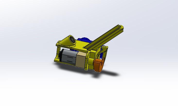
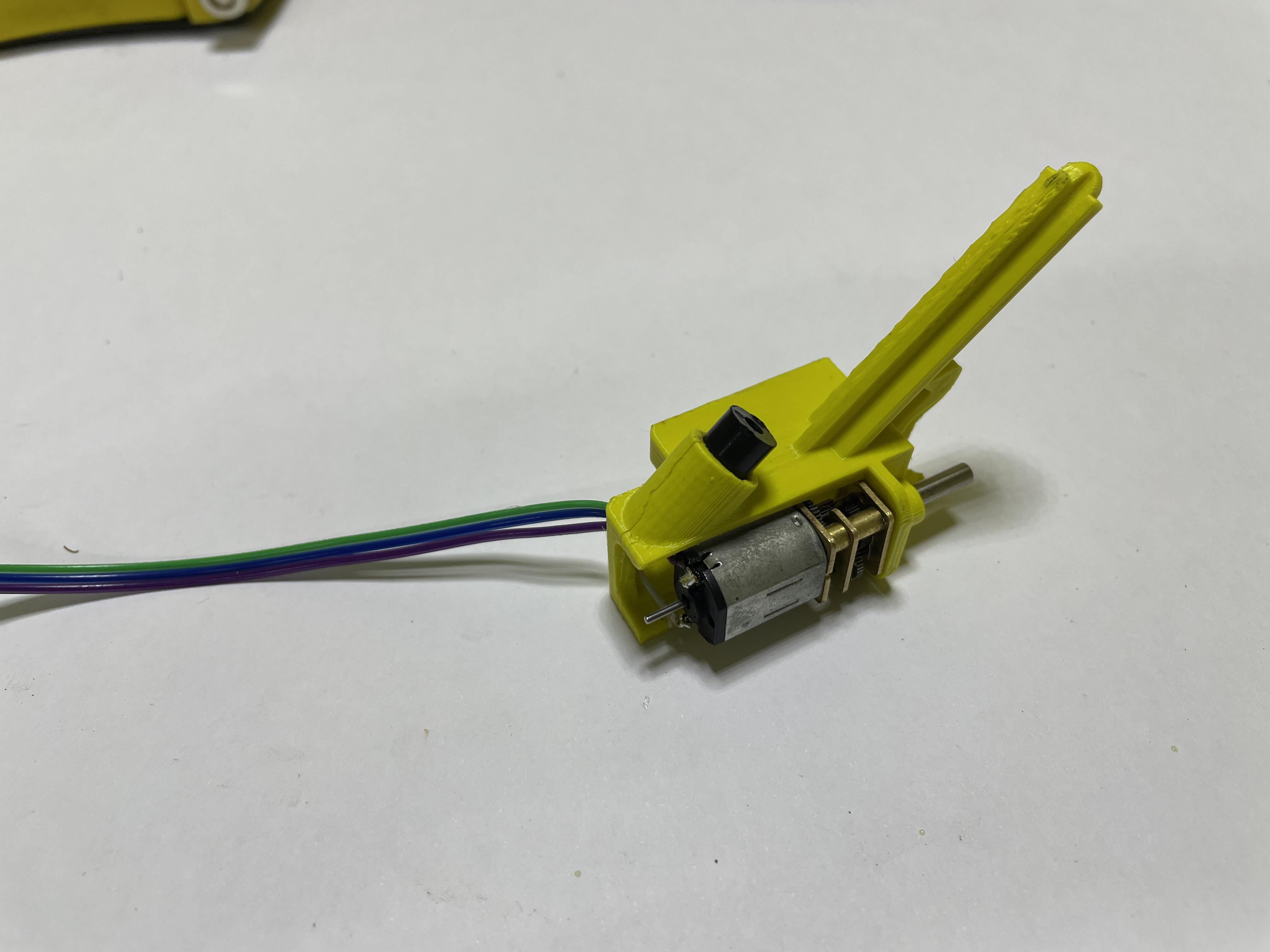
This other bit is slightly trickier to do but nothing impossible. First begin with soldering your wire to the laser diode and then pull the wire through the hole where the laser sits. I opted to connect the laser and the motor on a common 5V so I needed to add a wire going from the laser back to the motor. You can just use four wires and a four pin header to simplify your soldering a bit. At the other end of the cable I added a 3 pin connector for connecting to the board.
With the soldering done the micro servo just slots in and is fixed in place on its own.
At the end I drilled a small hole using a 1mm drill bit to screw in the motor. At this point I also added the wedge piece for moving the lever in order to shoot the dart. On the wedge I also drilled a 1mm hole and used a grub screw to secure it to the motor shaft.
I am quite happy with how the turret case turned out and proud of the way I utilized a compliant mechanism design in order to release the dart so I included the CAD files in case you want to modify the part for use in some other application.
Attaching the Turret


You can now add the turret onto the body The process is quite straight forward, push the servo on the stand and secure it with a screw. That's it, you're done.
On a side note, as the entire turret is held on with only one screw and all the cables are detachable it is technically modular so you can replace the front end with whatever you want. For example, you can add a sensor array of an ultrasonic and infrared sensor and tell it to follow people or an ESP camera and have it patrol your house. The possibilities are endless!
Giving It Some Brains


With the robot now full assembled and working* everything else it needs is some coding. The robot is remote controlled so the program itself is quite simple, just some serial communication and servo motor control. The code is fully commented so you can refer to the comments if anything is unclear.
Note: make sure to disconnect the bluetooth module from the arduino before uploading the sketch as you will receive an error that the board is unavailable if you don't
Downloads
Giving It Some Direction


For remote controlling purposes I used an app from the app store simply called Bluetooth for Arduino. The app is straight forward enough and has a built in gamepad mode (as an in-app purchase). Begin by connecting to the robot by selecting it from a list (make sure Bluetooth is enabled) and choose your connection mode. Once you're in a mode you wish to use configure the commands to match the app and you're good to go.
The commands that are send are fully customizable so you can choose your own commands that you want to send. You can even build a fully custom panel so you can add in things like speed control and more.
On the Play store there is a plethora of these apps but the one I found, Arduino Bluetooth Controlled Joystick seems to be the most similar to the one I used and can also be set up with custom commands.
A Wild Problem Appears!

At this point (which hopefully won't happen to you if you decide to make the project for your own) I encountered a problem regarding my power requirements. As I didn't really think about the power draw while designing the whole circuit I was really surprised to see the robot not really walking that much. What would happen is that it would just twitch when I pressed forward on the remote, hold still for a couple seconds and then just go crazy. What was happening here is that the Arduino was resetting every time the motors draw current.
I fixed this problem by adding in a big fat capacitor (shown on schematic in step 6) so that when the motors go, the Arduino can be powered for a brief moment by the capacitor until the power supply (battery) can catch up. The capacitor is connected between ground and five volt rather than the vin because it only needs to power the Arduino and not the whole circuit.
In doing this I did something, not sure what, that caused the power bank I was using to start, in the lack of a better word, glitching, which ultimately fried it. I now have no battery and I couldn't source one that would fit locally so for the time being I am powering it with a different, bigger battery connected using a USB extension cable.
You Are Now Done! Go Annoy Your Siblings


If you reached this point, congratulations, you're done with your build!
Now all that's left is to go and test it out. Charge your battery, turn on Bluetooth and have fun!
Disclaimer: even though the dart is not very powerful, never aim or shoot at people, animals, cars, planes or your mom's vases as you can get in trouble