Bluetooth Navigation / Digital Roadbook Controller (4 Buttons / 2 Profiles)
by StylesRallyIndustries in Workshop > Motorcycles
18385 Views, 116 Favorites, 0 Comments
Bluetooth Navigation / Digital Roadbook Controller (4 Buttons / 2 Profiles)


This low-cost and easy to construct ESP32 powered controller with 3d printed components will connect to your Mobile device and allow you to control Navigation / Roadbook applications via the 4 buttons.
I designed this controller so that when leading group rides I am able to quickly control my map while still riding at speed.
The default controls I use are Map Zoom In / Out, Map Centre on current location and Map Rotate / North.
The controller will also hopefully lower the barrier of entry to amature rally events as it can be used to control digital rally roadbooks.
Features:
- Designed to fit between the clutch perch / controls and the grip.
- Software supports 2 profiles for multiple applications.
- Updates are easy to apply for new functionality or upgrades.
- Built in step down converter for 12v+ connection to motorcycle or optional battery box.
- Weather Resistant rated at IP54.
- All components are widely available and inexpensive.
- Kits containing all required components, 3d printed parts with inserts and ESP32 with software pre-installed are also available.
Tested Applications:
- Locus Maps
- Rally Navigator
- Piste Rally Roadbook Reader
- DMD2 (W.I.P., not certified.)
Required Tools:
- 3D Printer.
- Soldering Iron.
- PC.
Any feedback you submit for features or improvements will be greatly appreciated!
StylesRallyIndustries<at>gmail.com
Have fun!
👊🏻✊🏻💨
--
Thomas Styles
--------------------------------------
Update - 01/12/2023
--
Software Updates;
V1.1 has been released on Github,
Added the missing bootloader and partition .bin files,
Enabled Serial Output for easier troubleshooting.
https://github.com/StylesRallyIndustries/RallyController/releases/tag/v1.1
New Product;
Control Unit USB (v1) -
Lower-cost, less complex with fewer components and easier to construct.
Requires USB power - no power button, no step-down convertor.
https://www.thingiverse.com/thing:6345115
Hardware Updates;
4 Button Rally Controller (v2) -
Improved Waterproofing,
Gasket now has inner lip to help set in position,
Added Cable Sleeve,
Slightly tweaked insert and bolt locations.
https://www.thingiverse.com/thing:6282694
Control Unit 12v (v2) -
Added Cables Sleeves,
Modified Power Button location and clearance,
Increased height of box by ~1mm to give more room for wiring.
https://www.thingiverse.com/thing:6345095
Control Unit Battery (v2) -
Added Cable Sleeve,
Improved ESP32 fit in seal due to differences with ESP32 models.
Added Power Button and removed Power Slider cutout and plug.
https://www.thingiverse.com/thing:6285930
--
Any questions or feedback please feel free to send me a Facebook Message or create a post on this page!
https://www.facebook.com/StylesRallyIndustriesNZ
Thanks,
Thomas
S.R.I.
--------------------------------------
Update 28/Oct/2023 -
I have uploaded the Control Box for a 18650 Battery Shield so you can run this independently from the bikes electrics.
--------------------------------------
Supplies


Controller and Control Unit (CU) STL files are available here:
https://www.thingiverse.com/stylesrallyindustries/designs
https://www.thingiverse.com/thing:6282694
Print in PLA+ or better:
- Controller Body
- Controller Clamp
- Controller Panel
- CU Body
- CU Lid
Print in TPU95a or similar:
- Controller Seal
- 4 x Button Seals
- CU Seal
Additional Supplies:
- Network Cable ~1m in length
- 4 x 12mm Momentary Push Buttons IP67
- Dupont Female Headers
- Heat Shrink
- Solderless Connectors
- ESP32 30PIN CH9102X
- DC-DC Step-Down Module LM2596
- Zip Ties
- Inserts and Bolts
- 5 x M3x6x4.2 Hot Melt Inserts
- 6 x M3x3x4.2 Hot Melt Inserts
- 2 x M3x20mm Socket Head Bolts
- 4 x M3x10mm Socket Head Bolts
- 3 x M3x10mm Button Head Bolts
- 2 x M3x5mm Button Head Bolts
Optional for 18650 Powered Control Box:
- 18650 Battery Shield and 18650 Battery.
- 4 x M3x3x4.2 Hot Melt Inserts
- 4 x M3x4x4.2 Hot Melt Inserts
- 4 x M3x5mm Button Head Bolts
- 4 x M3x12mm Socket Head Bolts
Alternatively visit the SRI Facebook Group to enquire about a full kit containing:
- All components listed test and confirmed to fit correctly.
- 3D Printed parts in high strength PETG resin enhanced with carbon fibre (threaded inserts installed).
- ESP32 with software pre-flashed.
Install Threaded Inserts

Install the threaded inserts using a standard soldering iron with a clean tip.
Insert size and location:
- 5 x M3x6x4.2 - Controller
- 6 x M3x3x4.2 - CU
Make sure that the smaller tapered end is placed into the appropriate hole then press down on the insert with the hot iron gently until it fits into position.
You can use something flat and metal (ruler, bolt etc) to press down and level the insert while still hot.
Installing the inserts straight is important to prevent the bolt pulling the insert out.
Install all the inserts on both the Controller and CU.
For additional tips you can check out this video from CnC Kitchen
Prepare ESP32


Flash the ESP32 with the .bin files found at the SRI Github using the following tool and instructions:
https://blog.spacehuhn.com/espwebtool#heading-esp-web-tool
Use the following Memory Assignments:
0x1000 RC.ino.bootloader.bin
0x8000 RC.ino.partitions.bin
0x10000 RC.ino.bin
Rally Controller Firmware .bin(s):
https://github.com/StylesRallyIndustries/RallyController/releases/tag/Public
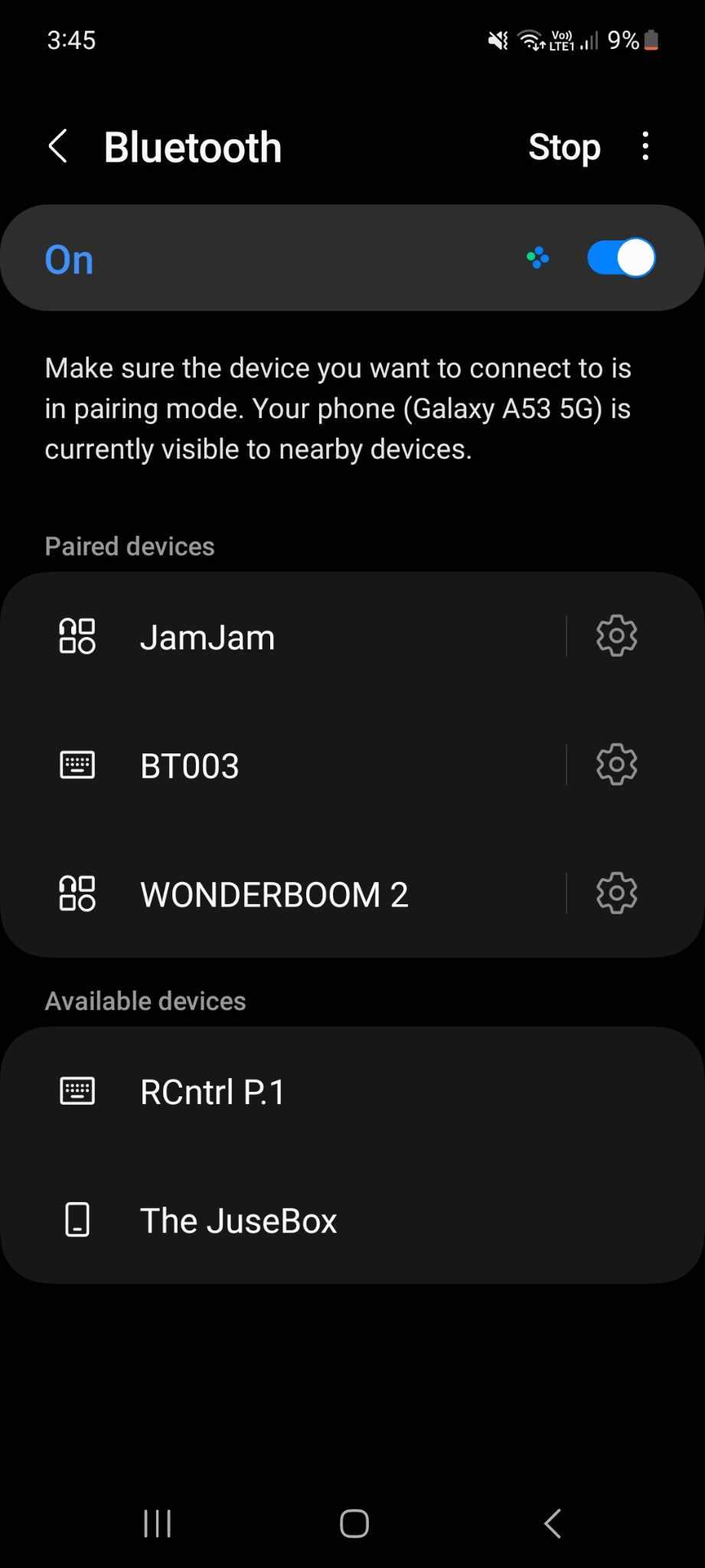
Confirm this has worked by using Bluetooth on your device to connect to the Controller 'RCntrl P.1' while the ESP32 is connected to your PC.
Optional: Visit the SRI Github for the latest software version and additional information.
Build Controller


Determine where you want to mount the Control Unit.
Measure and cut the length of network cable required (from controller position on left grip to intended CU mount point) and expose wires on one end.
Prepare the network cable and 4 twisted pairs of wires:
Protect connections with heat shrink.
- 4 solid colour (Brown, Green, Blue, Orange)
- 4 with matching colour and white stripes.
Using matching colours solder a Dupont female header / jumper wire to each of the solid colour network wires.
Using a solderless connector join the remaining 4 striped wires to 1 Black wire header for ground.
Feed the cut end of the network cable through the control cable hole on the CU, then through the hole on the Controller.
On the controller end cut the wires to length and expose the ends:
- Brown / Striped - 60mm
- Green / Striped - 50mm
- Blue / Striped - 30mm
- Orange / Striped - 10mm
Install each button in the controller, with external TPU seal, internal metal spring washer and nut.
The bottom of the controller is where the cable hole is located.
- Top (Button 1) -> Brown Wires
- Top Middle (Button 2) -> Green Wires
- Bottom Middle (Button 3) -> Blue Wires
- Bottom (Button 4) -> Orange Wires
Using a pair of needle nose pliers carefully wrap the exposed wires through the relevant button terminals.
Place the small sections of heat shrink onto the wires before soldering.
Drop a nugget of solder onto each connection.
You can now test with a multimeter on the headers in the CU.
Any solid colour to the ground (black) should complete a circuit when the related button is pressed.
Protect connections with heat shrink.
I use a Bic Lighter as the 3d printed material can soften at when using a heat gun.
Optional: Seal the cable hole with hot glue or similar.
Carefully fit the TPU seal inside the side panel and secure with the 3 x M3x10mm button head bolts.
Build CU


Insert the 12v INPUT lines from your power source into the marked hole, and solder to the appropriate INPUT connections.
Solder wires from power button (if using) to appropriate INPUT terminals on converter.
Important: When using the adjustable Step Down converter you will need to ensure the output is set to ~5v with a multimeter.
Solder Dupont female headers to the OUTPUT terminals on the convertor.
Red for Positive and Black for Ground.
Install the converter using the 2 x M3x5mm bolts button head bolts.
Route the cables under the converter if needed.
Connect all the headers to the appropriate pins on the ESP32:
Button1 (Brown) = 18;
Button2 (Green) = 19;
Button3 (Blue) = 25;
Button4 (Orange) = 26;
Button Ground (Black) = any GND
Power Input Positive (Red) = VIN
Power Input Ground (Black) = any GND
Optional: Seal the cable holes with hot glue or similar.
Install ESP32 in the correct orientation, the USB port sits next to the power button hole.
The arrows on the seal and inside the lid should both point towards the power button hole.
Ensure the seal and lid fit snugly before using 4 x M3x10mm socket head bolts to secure lid.
Optional - Build Control Box


Control Box files for a 18650 Battery Shield can be found on the S.R.I. Thingiverse Page.
This will allow you to power the Rally Controller from the Control Box. You can charge the battery while the controller is running. Micro B USB cable required.
Install the Threaded Inserts:
Base / Battery Shield:
- 4 x M3x3x4.2 Inserts
- 4 x M3x5mm Button Head
Lid:
- 4 x M3x4x4.2 Inserts
- 4 x M3x12mm Socket Head
Solder a Positive and Ground Female Header to Power Out.
All other instructions are the same.
Install on Motorcycle


Position the clutch perch / controls to create a 5mm gap away from the grip for the controller clamp.
Supply 12v from Switched ACC or Battery to the INPUT wires for the CU.
Important: If connecting straight to battery ensure you use an in-line fuse holder to protect your motorcycle.
Secure Control Unit to mount location.
Between the handlebars and the top triple clamp works well.
Clamp Controller to handlebar with 2 x M3x20mm socket head bolts and square up cables with zip ties.
Finished!
Using the Controller


Initial set up:
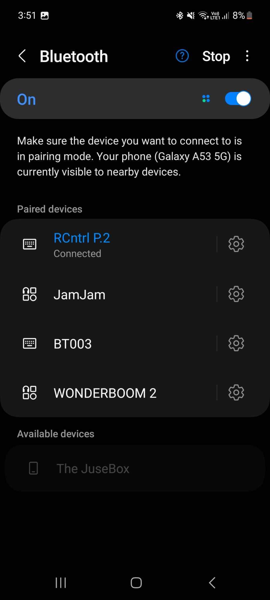
Once powered you can pair your phone or device to the controller.
When in range your phone will automatically connect to the powered controller.
Toggling Profiles:
Hold down the Top and Bottom buttons for ~5 seconds to toggle between profiles.
You can confirm which profile is selected by pressing 'scan' on the Bluetooth connection screen on your phone.
The controller will return to Profile 1 when powered off and on.
Default Configuration:
Profile 1 - Locus Maps / DMD2 / Map Navigation
DMD2 support is hacked in, there is a change coming from the very helpful DMD2 team which will make controller support easier. For now I am emulating the basic functions on the map screen only. The beta version of DMD2 is required and control support could stop functioning at any time. I will continue to improve this integration.
- Button 1 - Map Zoom In
- Button 2 - Map Zoom Out
- Button 3 - <Nothing>
- Button 4 - Map Centre on Current Location / Rotate
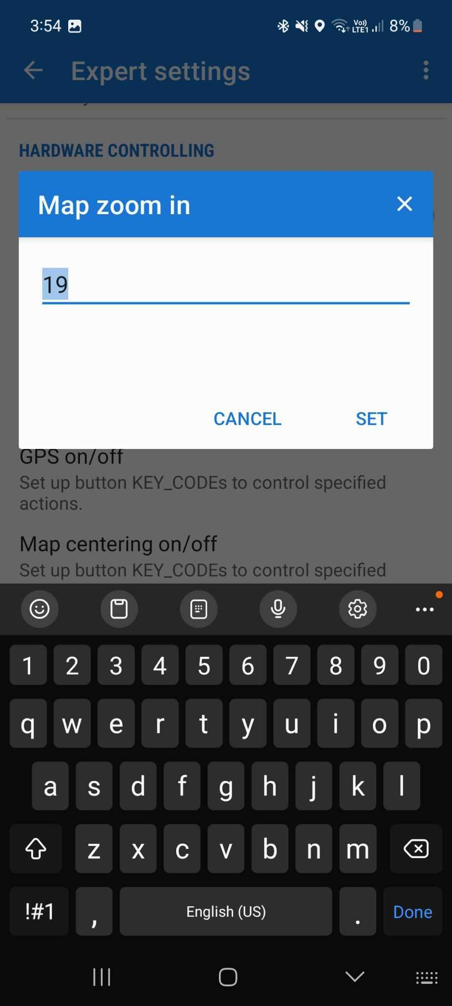
Locus maps requires you to change the expected keys to match the constant values as listed.
Activate Expert Mode:
Long press on the Locus main menu button (3 horizontal lines, top left) and tap Expert settings.
Settings -> Expert Settings -> Hardware Controlling
- Button 1 - Map Zoom In (Constant Value: 70)
- Button 2 - Map Zoom Out (Constant Value: 69)
- Button 3 - Map Rotate / Fixed North (Constant Value: 46)
- Button 4 - Map Centre on Current Location (Constant Value: 31)
Profile 2 - Piste / Rally Navigator Roadbook Reader
- Button 1 - Scroll Roadbook Up
- Button 2 - Scroll Roadbook Down
- Button 3 - Adjust Tripmeter Down
- Button 4 - Adjust Tripmeter Up
Advanced Configuration:
Profile 1 - the default profile uses the following keycodes:
- Button 1 - '='
- Button 2 - '-'
- Button 3 - 'R'
- Button 4 - 'C'
Profile 2 - the secondary profile uses the media keycodes:
You can also use this Profile to control music apps
- Button 1 - Play Previous (KEY_MEDIA_PREVIOUS_TRACK)
- Button 2 - Play Next (KEY_MEDIA_NEXT_TRACK)
- Button 3 - Volume Down (KEY_MEDIA_VOLUME_DOWN)
- Button 4 - Volume Up (KEY_MEDIA_VOLUME_UP)
Do with this information what you wish!
Links
Tech / Build Support and Info on New Projects:
https://www.facebook.com/StylesRallyIndustriesNZ
STL Files:
https://www.thingiverse.com/stylesrallyindustries/designs
ESP32 Software:
https://github.com/StylesRallyIndustries/RallyController
If you'd like to contribute to this project: