Bluetooth Speaker With DSP From Upcycled Guitar Practice Amp
by zx82net in Circuits > Speakers
3874 Views, 30 Favorites, 0 Comments
Bluetooth Speaker With DSP From Upcycled Guitar Practice Amp
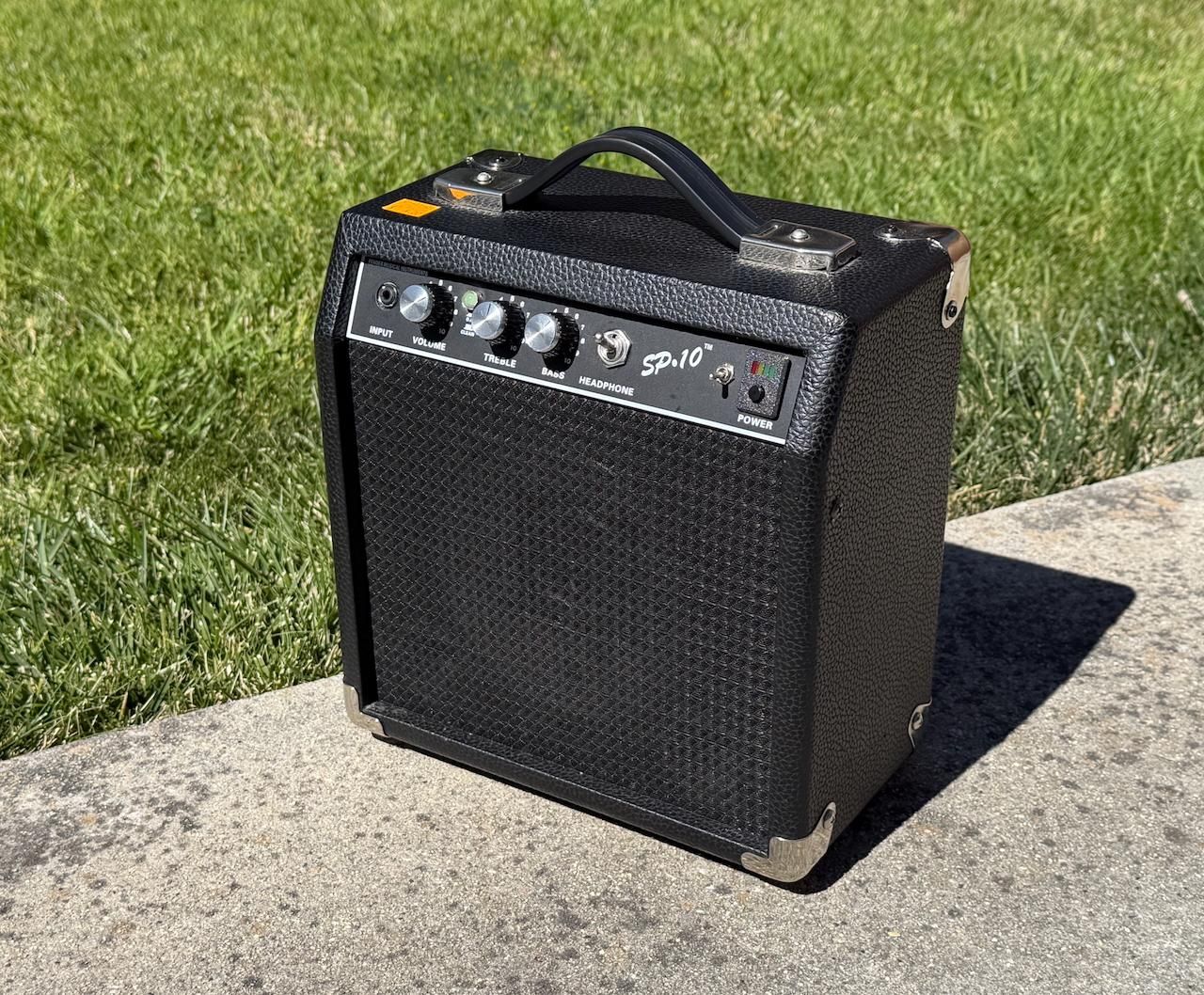
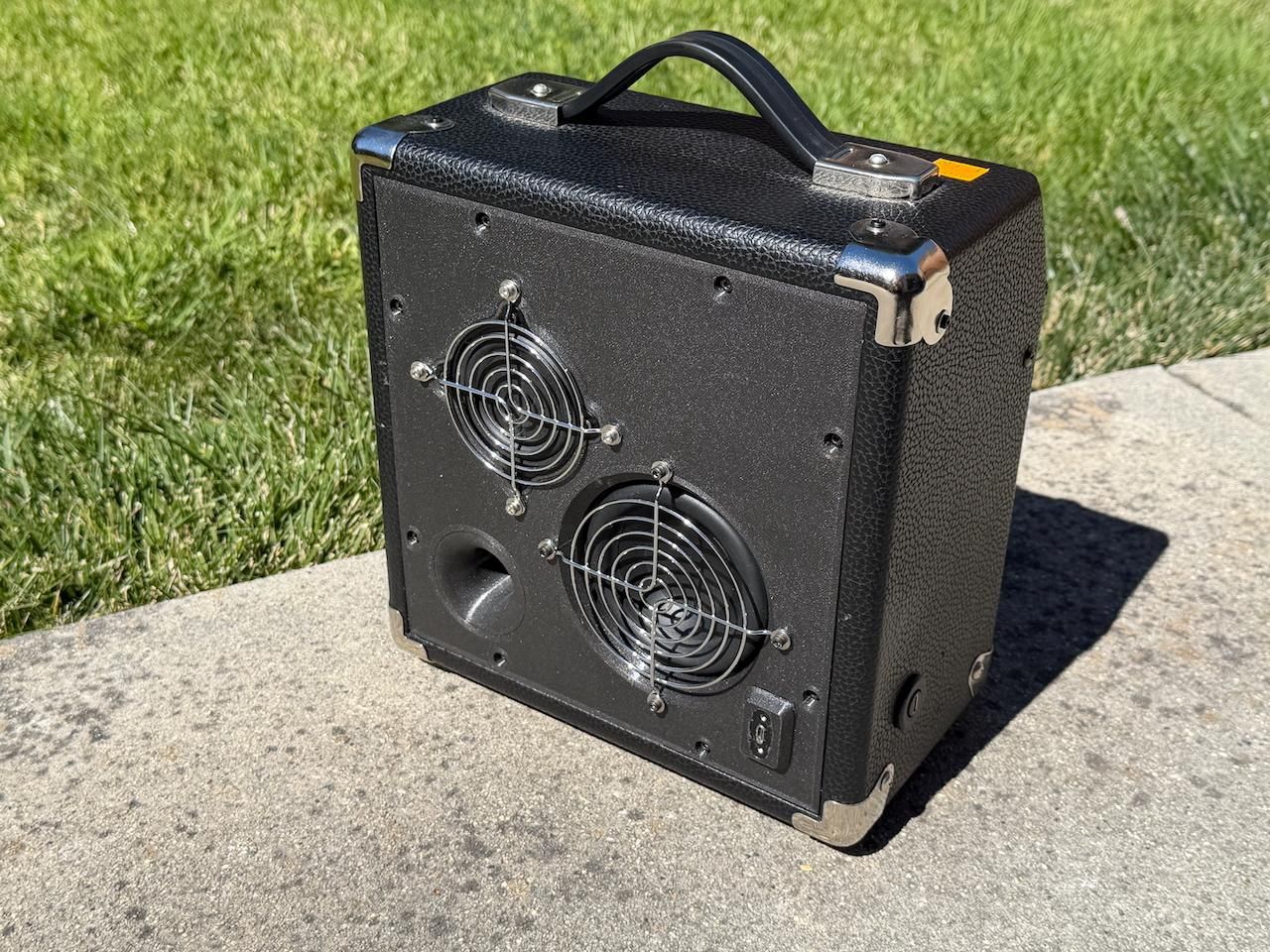
This started with a $4 purchase: an empty Fender 10G practice amp cabinet, sitting around looking for a second life. It's now a great sounding Bluetooth speaker with controls to easily adjust it for any placement, indoors or outdoors, against a wall or in the middle of a room. It runs for hours off the internal rechargeable battery and charges with UCB-C. It'll make a great addition to any summer garden party.
I'll describe this build in detail, but also explain how to adapt the design to use whatever cabinet and drivers you have to hand.
Under the vintage grille cloth is a DSP-based system that can reshape itself to suit wherever it's playing, and deliver the performance of a high end Bluetooth speaker in your own custom build:
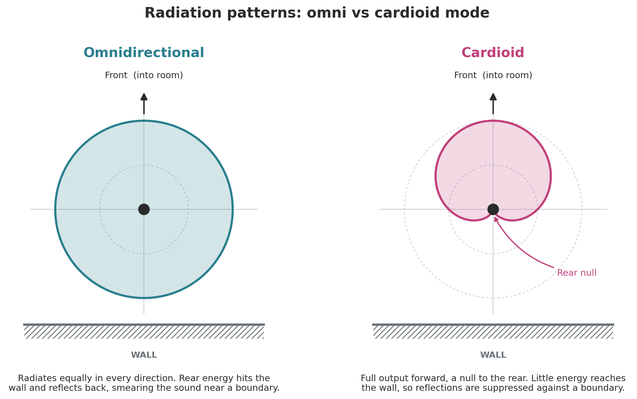
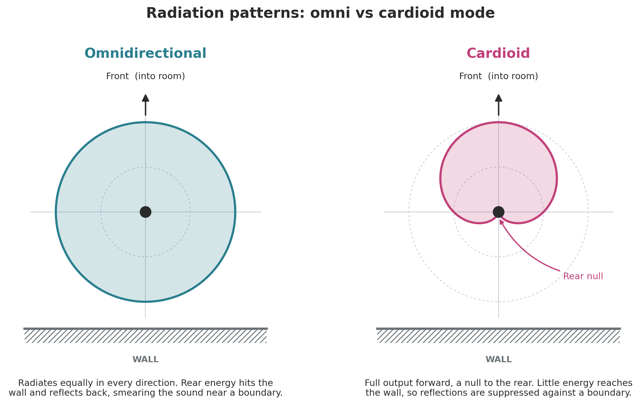
- Switchable directivity: Cardioid and omnidirectional. A switch changes the speaker between omnidirectional (radiating evenly in all directions, good in the middle of a room or outdoors) and cardioid (projecting forward and cancelling the sound behind, which improves clarity when sited against a wall).
- Room-compensation tone controls. A bass shelf control compensates for room loading, the bass lift you get near walls and corners. A treble gradient control tilts the response from 1 kHz to 20 kHz, so you can set the overall brightness to suit the room and your own taste.
- Bass boost and dynamic bass limiter. At low listening levels the speaker gives you generous bass boost. At high volumes, the DSP progressively reduces the boost so the amplifier and power supply never runs out of headroom to the point that it distorts and the port never chuffs. You get as much bass as the hardware can cleanly deliver, at every volume.
The drivers: a 4" woofer firing out the back of the cabinet (Step 3 explains why that works), and a pair of BMR full-range drivers, one front and one rear, handling everything above 250 Hz. The rear full-range is what makes the directivity switching possible. The measured frequency response is 50Hz to 20kHz.
This guide is written to be skimmed. If you already know how to pick drivers, skip that section and dig into the DSP. If you know SigmaStudio, grab the tricks and skip the woodworking. All the design files are included: CAD for the 3D printed parts (STL, STEP, and a Fusion 360 archive) and the complete SigmaStudio project.
Supplies
Equipment
- 3D printer
- Soldering iron (optional)
- Screwdrivers
- Calibrated microphone
- USB in-circuit programmer for DSP (e.g Dayton Audio KPX, Wondom ICP5)
Software
- CAD software for the 3D printed components (I use Fusion 360)
- SigmaStudio for the DSP (free)
- REW — Room EQ Wizard, for response measurements (free)
Components
- Donor cabinet (I used a Fender 10G, bought as an empty box)
- Dayton Audio TCP115-4 4" woofer (LF)
- 2× Tectonic TEBM46C20N-4/B BMR full-range drivers (HF, front and rear)
- Dayton Audio KABD-430 4×30 W DSP amplifier board (Wondom JAB4 is functionally identical)
- Dayton Audio LBB-3v2 3× 18650 lithium battery charger board (Wondom BCPB2 is functionally identical)
- 3× 18650 lithium cells
- USB-C to DC power supply board (~$5, e.g. https://a.co/d/0gA2zVeF)
- Panel-mount USB-C socket, wired to a male USB-C plug on the inside (~$15, e.g. https://a.co/d/0j9u0s9i)
- Dayton Audio LBB-5CL cable kit, for the battery board (or Wondom equivalent)
- Dayton Audio KABD-SPF cable kit, for the amplifier (or Wondom equivalent)
- 2× steel wire fan guards to protect the rear-firing drivers (92 mm for the woofer, 80 mm for the rear BMR)
- M3 stand-offs for mounting battery board (e.g. https://a.co/d/06GuUcHp)
- optional extras: vintage style control knobs, and chunky toggle switch for power, rectangular LED's for the battery indicator
Consumables
- Printer filament (I used PETG throughout)
- Glue (I recommend Gorilla Glue)
- Blu Tack
- Wood screws
- 3 mm machine screws
- Heat-set threaded inserts
- Self-adhesive gasket tape
- Polyfill or suitable stuffing for the HF enclosures
Design Goals & Concept
Every feature in this build exists to solve a specific problem. Before getting into drivers and DSP blocks, it's worth walking through those problems, because this is where you decide which ones your build actually has.
Problem 1: A portable speaker never plays in the same place twice.
A hi-fi speaker gets positioned once, in one room, and tuned for that spot. A portable speaker moves around: kitchen counter in the morning, patio table in the afternoon, bookshelf against a wall in the evening. Each placement changes the sound, and not subtly.
Two placement effects dominate. The first is room loading: put a speaker near a wall and the bass rises, put it in a corner and it rises more, take it outdoors away from all boundaries and the bass largely disappears. The swing between outdoors and an indoor corner can easily exceed 6 dB in the low frequencies, the difference between thin and boomy from the same speaker playing the same track. The fix is a bass shelf control: a front panel knob that sweeps a low frequency shelf from around +15 dB of boost (outdoors) down to a few dB of cut (in a corner).
The second effect is rear-wall reflection. A speaker radiating in all directions sends as much energy backward as forward. In the middle of a room or outdoors that's a feature, since everyone around the speaker hears the same thing. Against a wall it's a problem: the rearward sound bounces off the wall and recombines with the direct sound, smearing the midrange. The fix is switchable directivity: an omnidirectional mode for open placements, and a cardioid mode that uses the rear-facing driver to cancel the rearward radiation when the speaker is against a wall.
Problem 2: Rooms sound different, and so do ears.
Beyond placement, rooms vary. A tiled kitchen is bright and lively, a curtained bedroom is soft and damped. Listeners vary too; the gently downward-tilted response one person prefers sounds dull to another. Rather than a conventional treble knob, which lifts the whole top end and quickly sounds artificial, this build uses a treble gradient control: a progressive tilt from 1 kHz to 20 kHz. Small adjustments change the overall brightness smoothly, so you can tweak it to suit the room you're in, or the occasion.
Problem 3: Maximizing bass response within the capacity of the amplifier and battery.
The bass shelf hands out up to 15 dB of boost. That's a factor of about 30 in power. No 60 watt battery-powered amplifier survives that at high volume, and before the amp even clips, the port can start chuffing as air velocity climbs. The usual answer is to just not offer that much boost, sacrificing low-level listening quality to protect the worst case.
The better answer is a dynamic bass limiter. The DSP continuously watches the signal level and, as volume rises, progressively takes back the bass boost: 1 dB of boost surrendered per 1 dB of level above a calibrated threshold. At low and moderate volume you get the full low end. Push toward maximum and the system smoothly trades bass extension for clean output. Done right it's inaudible as an effect; the speaker just always sounds like it's working comfortably. Getting it right occupies a good chunk of the DSP section, and it's the part of this build most worth borrowing.
Adapting this design to your own build. Depending on what components you're starting with and what you want from your build, some elements of this design may transfer directly and others may not be needed. I'll explain how each part of the design works, so you can decide what's relevant to your goals. A fantastic thing about working with a DSP based system is how simple it is to experiment and try things out. One strong recommendation I would make is investing in a low cost calibrated microphone, and learning how to take measurements. It'll allow you to understand the changes you are making, and will do more for your sound quality than spending a load on high-end drivers. Some people will say designing by ear is all you need, because you listen with your ears. In truth, when you tune a speaker system by ear you are just tuning for the environment you are testing in. If you want to design your own speaker that will sound great wherever you take it, it is well worth understanding the changes you make, and being able to measure the output is an important part of that.
Acoustic Architecture
The driver arrangement is the unusual part of this design, so it's worth explaining properly. There are three drivers: a 4" woofer firing out the back of the cabinet, and two BMR full-range drivers, one on the front baffle and one on the rear. The woofer handles everything below 250 Hz, and the BMRs everything above.
Why a rear-firing woofer works. Sound radiation only becomes directional when the source is large compared to the wavelength. At 250 Hz the wavelength is about 1.4 m, several times bigger than this cabinet, so the woofer's output wraps around the box and radiates in all directions no matter which way the driver points. Below the crossover it makes essentially no acoustic difference whether the woofer faces front or back. That frees up the placement decision to be made on practical grounds: putting the woofer and port on the back leaves the front baffle clear for the BMR and the original control panel, and keeps the vintage face of the amp intact.
Why BMRs up top. Above the crossover, directivity is the whole game in this design, and that's what led to the driver choice. BMR (Balanced Mode Radiator) drivers hold their wide dispersion much higher in frequency than a conventional cone, which matters twice over here: it keeps the omnidirectional mode genuinely omnidirectional rather than beaming at the listener, and it keeps the front and rear drivers behaving alike off-axis, which the cardioid trick depends on. They're also tolerant of thick grille cloth, which a guitar cabinet has plenty of.
The crossover. The two sections meet at 250 Hz with 48 dB/octave Linkwitz-Riley slopes. That's a steep crossover by passive standards, but in DSP it costs nothing extra to design and only a modest number of instructions to run, and the steep slopes work hard here. They keep bass excursion out of the BMRs, which are small drivers being asked to play at real volume, and they confine the woofer to the range where its rearward placement is acoustically invisible. Below all of this sits a 55 Hz high-pass filter protecting the port: content below the tuning frequency just unloads the driver and makes chuffing noises, so it's removed before it gets the chance. The enclosure modeling behind these numbers — box volumes, port tuning, and where each driver runs out of steam — is covered as the worked example in Step 4.
Time alignment. The woofer and front BMR sit on opposite faces of the cabinet, and the HF path also picks up some group delay from its equalization. To align them I gave the HF path a 0.5 ms delay, tuned by measurement: temporarily invert the polarity of one driver, play a tone at the crossover frequency, and adjust the delay for the deepest null in front of the speaker. Flip the polarity back and you know the two sections are summing properly through the crossover region. It's a satisfying technique because you're adjusting for a sharp minimum rather than a broad maximum, which is far easier to find.
The cardioid mode. This is the feature that makes the speaker work well against a wall, and mechanically it's simple: in cardioid mode, the rear BMR is fed the same signal as the front, but delayed by 1 ms and inverted.
Here's why that produces a forward-facing beam. Behind the speaker, the sound from the front driver takes about 1 ms to travel around the cabinet. The rear driver, playing an inverted copy delayed by that same 1 ms, launches exactly the opposite pressure at exactly the right moment, and the two cancel. In front of the speaker the geometry is reversed: the rear driver's output arrives late twice over (the electronic delay plus the travel time around the box), and instead of cancelling it reinforces through the frequency range that matters. The result is a cardioid pattern: full output forward, a null to the rear.
I picked the 1 ms delay by design, from the path length around the cabinet, then confirmed it by measurement: microphone behind the speaker, nudging the delay up and down until the null was as deep as it would go. In omni mode the trick is switched off and both BMRs simply play the same signal, front and back.
The practical payoff: against a wall, the cardioid mode stops the rear radiation from bouncing off the wall and smearing the sound, and the presentation firms up noticeably. In the middle of a room or outdoors, omni mode radiates evenly to listeners on all sides.
Choosing Drivers
The first thing to say: this architecture is unusually forgiving about driver choice, and that's not an accident. Almost everything that normally makes driver substitution painful — matching sensitivities, crossover design, response flattening — is handled in the DSP, in software, where changing it costs nothing but a measurement session. Swap in different drivers and the crossover frequency is a text box, the level matching is a slider, and the EQ reshapes itself to whatever your measurements say. The drivers just have to meet a few genuinely acoustic requirements that no amount of DSP can fake, and those are what this section is about.
Start with the volume budget. Your donor cabinet has a fixed internal volume, and everything has to live inside it: the LF enclosure, the HF enclosures, the electronics cavity, the battery, and all the internal structure. Measure your cabinet's internal dimensions, compute the volume, then subtract generously for what the internals displace. That budget, more than anything else, determines what woofer you can use. The worked example below shows how mine divided up.
The HF drivers set the floor of their own job. Whatever handles the top needs to run comfortably from your crossover frequency upward — in this design, from 250 Hz — in a small sealed enclosure. Small matters twice: the enclosure has to fit inside the cabinet twice over (front and rear), and a physically small driver keeps its dispersion wide up to high frequencies, which both the omni mode and the cardioid trick depend on. This is why I used BMR drivers: they're specifically engineered to hold wide dispersion far beyond where a cone of the same size starts to beam, and as a bonus they're untroubled by thick grille cloth. But any small, well-behaved full-range driver gets you most of the way.
The LF driver has one hard requirement and one soft one. The hard one: it has to work properly in whatever volume is left after the HF enclosures and electronics take their share — model it before you buy. The soft one: its passband has to stay below the frequency where the cabinet starts to make output directional, because the rear-mounting trick relies on bass wrapping around the box. For a cabinet this size, keeping the woofer below 250 Hz leaves a wide safety margin; a much bigger cabinet would push that ceiling down somewhat, but if you're converting something the size of a refrigerator you have different problems.
The crossover frequency is where these meet. Pick it where the HF driver is comfortable (with EQ help — see the worked example), the LF driver is still omnidirectional, and both drivers are operating well inside their limits. There's usually a comfortable overlap region rather than a single right answer.
Impedance and the amplifier. Check your driver impedances against what your amp board can drive. My LF channel is two 30 W channels bridged, which wants a 4 Ω load and is why the TCP115-4 (the 4 Ω variant) got the job; the BMRs are likewise 4 Ω on their individual channels. If you use a different amp board, its bridging rules and minimum impedances will steer your variant choices.
How I came up with my design
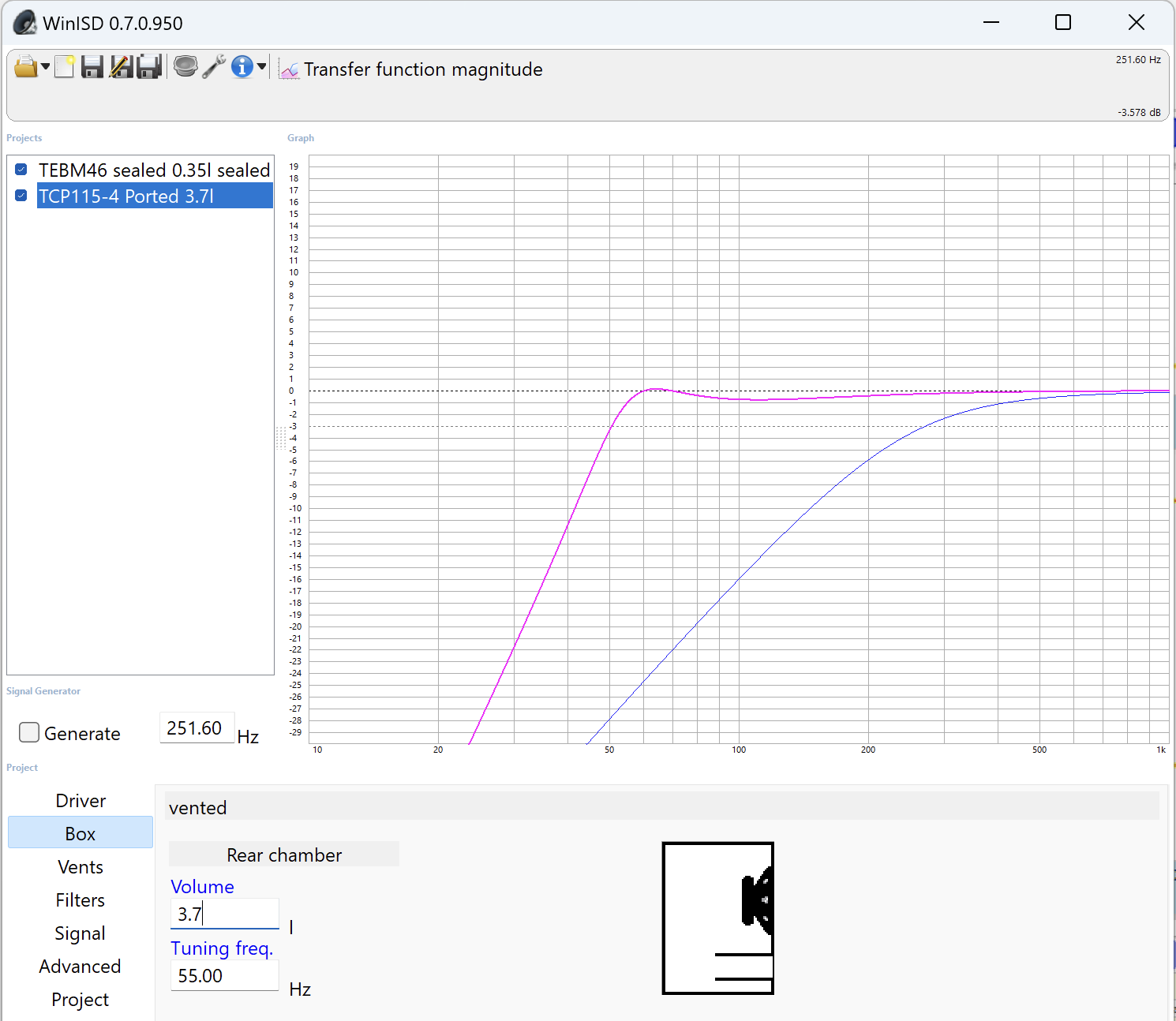
I modeled both enclosures in WinISD (free). The simulation shows the two transfer functions together: the woofer in magenta, the BMR in blue.
The TEBM46C20N-4/B BMR in 0.35 litres, sealed. Each Tectonic BMR gets a small sealed 3D-printed enclosure. The model shows it reaching −3.5 dB at 250 Hz — falling, but gracefully, with the controlled 12 dB/octave rolloff of a sealed box. That's exactly the deficit the +5 dB low shelf in the HF EQ (section 8b) props up: the enclosure model and the EQ design are two views of the same decision. This is the general pattern for the HF side: choose an enclosure size that gets the driver *near* the crossover with a well-behaved rolloff, then let a modest EQ shelf close the gap. What you can't do is EQ your way out of a driver that's genuinely out of steam — a few dB of shelf is cheap insurance, 15 dB of shelf is asking a small driver for excursion it doesn't have.
The TCP115-4 in about 3.7 litres, ported, tuned to 55 Hz. "About" because I didn't measure the displacement of every bracket and cable inside — box modeling tolerates a little volume uncertainty. The tuning I did pin down properly, using an impedance measurement: a ported box shows a characteristic double peak in its impedance curve with a minimum at the tuning frequency, so you can confirm where the box is actually tuned without trusting the volume estimate at all. The model shows the response essentially flat down to the 55 Hz tuning point, below which the 55 Hz high-pass in the DSP takes over and protects the driver. From there down it's the bass shelf, the room, and the limiter negotiating between them.
If you can't find the BMRs. Availability of the Tectonic drivers has become spotty — Parts Express appears to have stopped stocking them. A promising low-cost alternative is the Dayton Audio DMA45-4: around $9, a similar enclosure volume requirement, 4 Ω like the original, and though it's a conventional 1.5" aluminum cone rather than a BMR, at that size it stays wide-dispersion simply by being small. I haven't built with it, so treat it as a well-reasoned suggestion rather than a tested one — and as this section hopefully makes clear, the design will tell you what it needs once you measure.
Sealing a Deliberately Leaky Box
A guitar amp cabinet is not trying to be airtight. It's a resonant, rattly, gap-filled box, and for its original job that's fine — even part of the charm. For this build it's a problem: the woofer's ported enclosure only behaves as modeled if the box holds pressure, and every unplanned leak lowers the Q of the tuning, wastes bass output, and adds its own little chuffing noises. Sealing the cabinet properly was a bigger share of the work than I expected, so here's the full accounting. Your donor cabinet will leak in different places, but probably in the same *kinds* of places.
How to find leaks (and confirm they're fixed). Install the woofer, play a constant tone at the port tuning frequency, and go hunting with your ears — leaks at tuning are loud and localized. The impedance measurement gives the same answer more formally: a leaky ported box shows a weak, shallow minimum between the two impedance peaks, evidence of poor Q. I found my worst leak exactly this way; more on that below.
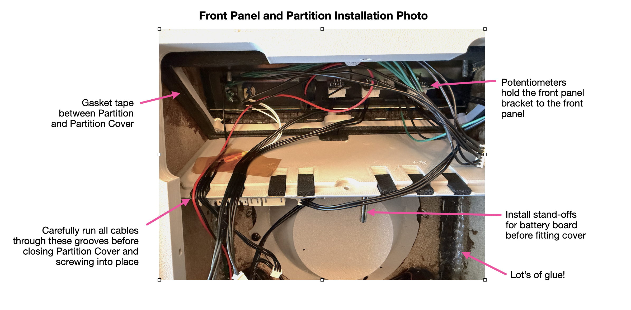
Leak path 1: the control panel. The 10G's control panel is a bent steel sheet fixed to the top panel, bridging a gap between the top panel and the front baffle, with no seal at its edges. Rather than trying to seal the steel itself, I designed a 3D printed partition that fits snugly against the side panels and screws into both the front baffle and the top panel, closing off the whole control cavity from the LF enclosure volume. I applied glue to the mating surfaces before screwing it home, then painted more glue along the joints afterwards with a brush. A screw-mounted access plate in the partition lets you get at the back of the control panel for installing the pots and switches and dressing the wiring — sealed with gasket tape where it meets the partition.
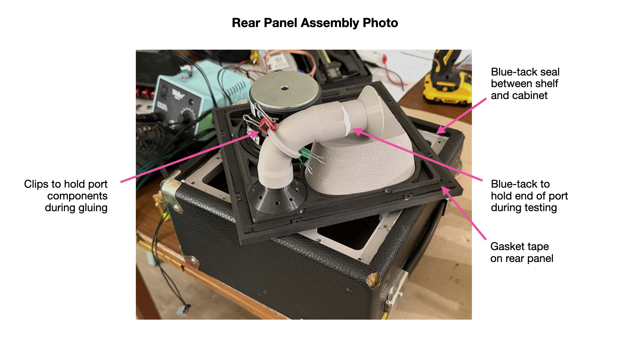
Leak path 2: the back panel. The original back panel just rests loosely in its opening on some roughly positioned chipboard off-cuts that don't even form a complete shelf. I replaced the whole thing with 3D printed parts — the largest prints in the project, the panel itself at 22.5 × 23.5 cm. A full-perimeter shelf attaches inside the cabinet, resting on the existing chipboard mounts and screwed into the side panels. I left a bevel along the shelf's edge so that a continuous 360° bead of Blu Tack could be worked into the gap between shelf and cabinet walls, pushed well in with a screwdriver. The rear panel then screws down onto the shelf against gasket tape. Two details here earn their keep:
- The gasket tape sits in a groove in the rear panel, dimensioned so the foam compresses enough to seal while the panel still lands plastic-to-plastic on the shelf — a controlled crush rather than a squishy joint.
- The panel mounts with machine screws into heat-set threaded inserts in the shelf. Everywhere else in the build I let machine screws self-thread into bare plastic holes, which is fine for assemble-once joints — but the rear panel comes on and off constantly during assembly and tuning, and self-threaded plastic won't survive that. Spend the inserts where the screw cycles are.
Leak path 3: the front baffle. I kept the original speaker cloth for the aesthetic, and that decision has a sealing consequence: the cloth is stretched around the front baffle, and the baffle mounts into the cabinet with the cloth loosely sandwiched between its edge and the side and bottom panels — a built-in leak the whole way round. My first attempt, painting glue around the inside edges of the baffle, wasn't enough: with the driver installed and a tone at the tuning frequency, it still leaked audibly, and the impedance curve showed the telltale weak minimum. A second pass with a thicker bead of glue straight from the bottle, left to fully cure, did the trick. The lesson: with fabric in a joint, thin glue wicks into the cloth and vanishes; you need enough body to bridge the gap.
The smaller stuff. The original reflex ports are stopped with 3D printed plugs, glued in place. The cable exits from the HF enclosures are filled with Blu Tack. The front HF enclosure seals to the front baffle with gasket tape, compressed by wood screws driven from the rear.
On the glue. All the glued joints use Gorilla Glue Clear: long working time, decent gap filling, and no mixing, unlike a two-part epoxy. Blu Tack deserves a mention as a sealing material in its own right — it's removable, conforms to awkward gaps, and holds an airtight seal indefinitely in the places you might need to revisit.
3D Printed Internals and Step B Y Step Assembly Process
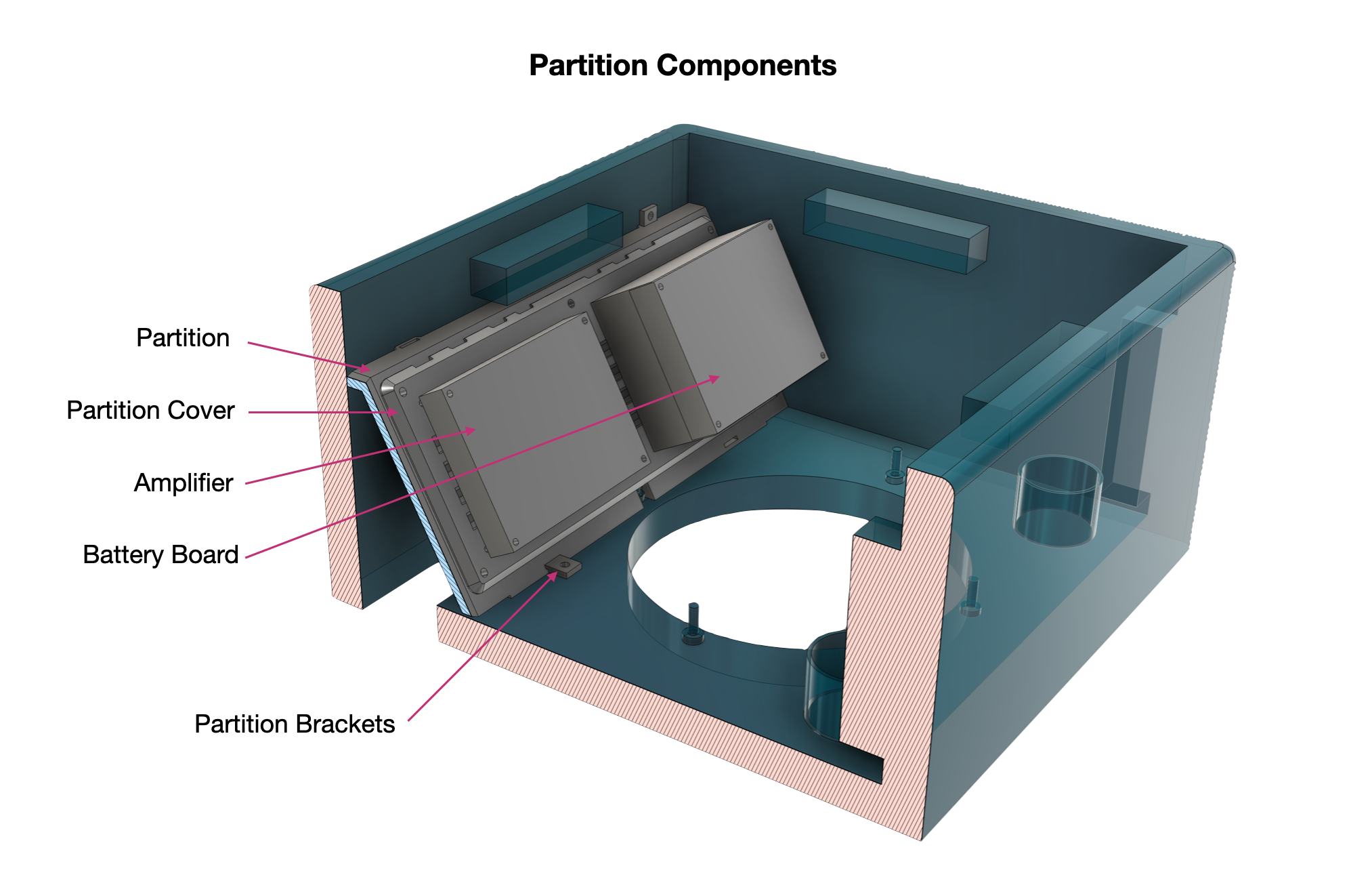
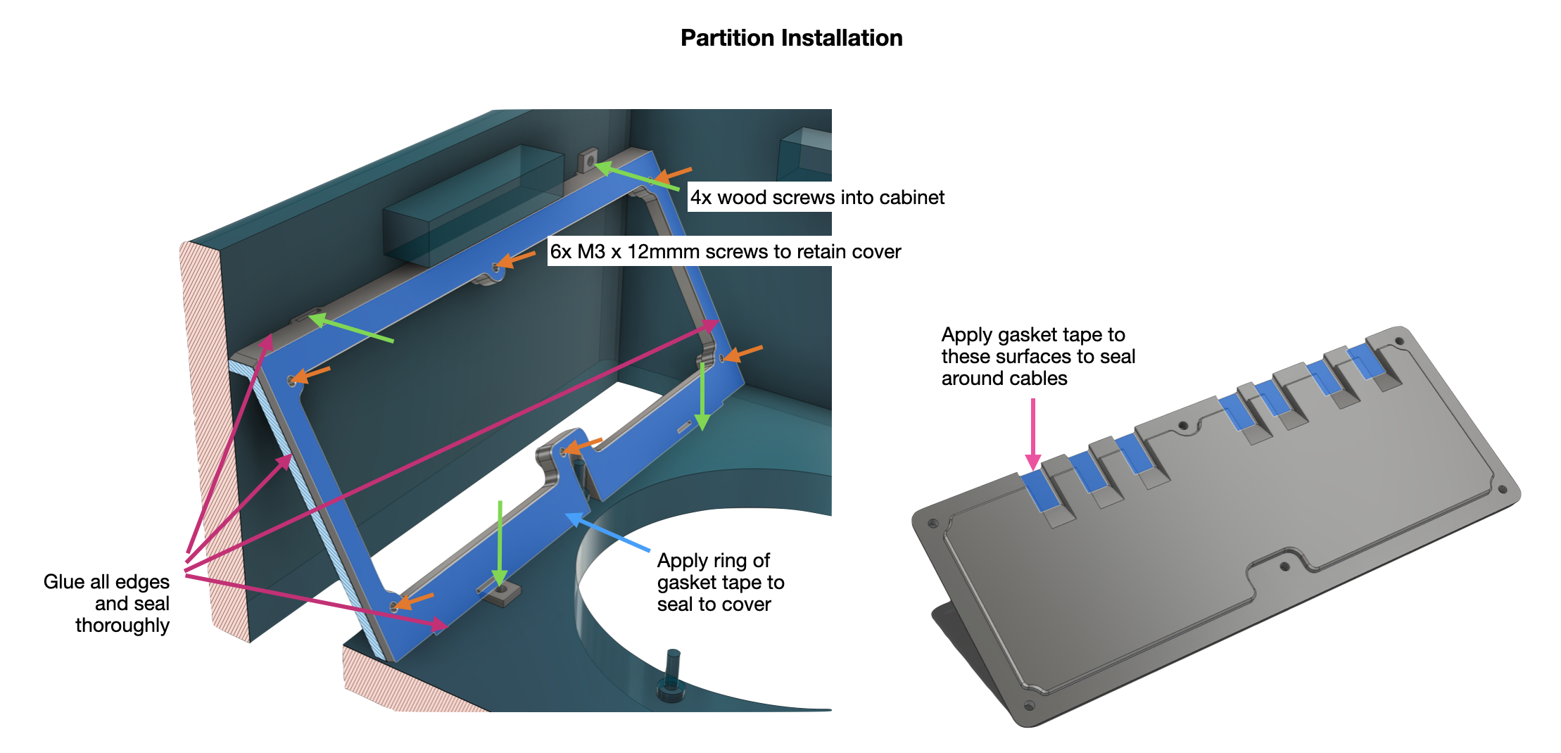
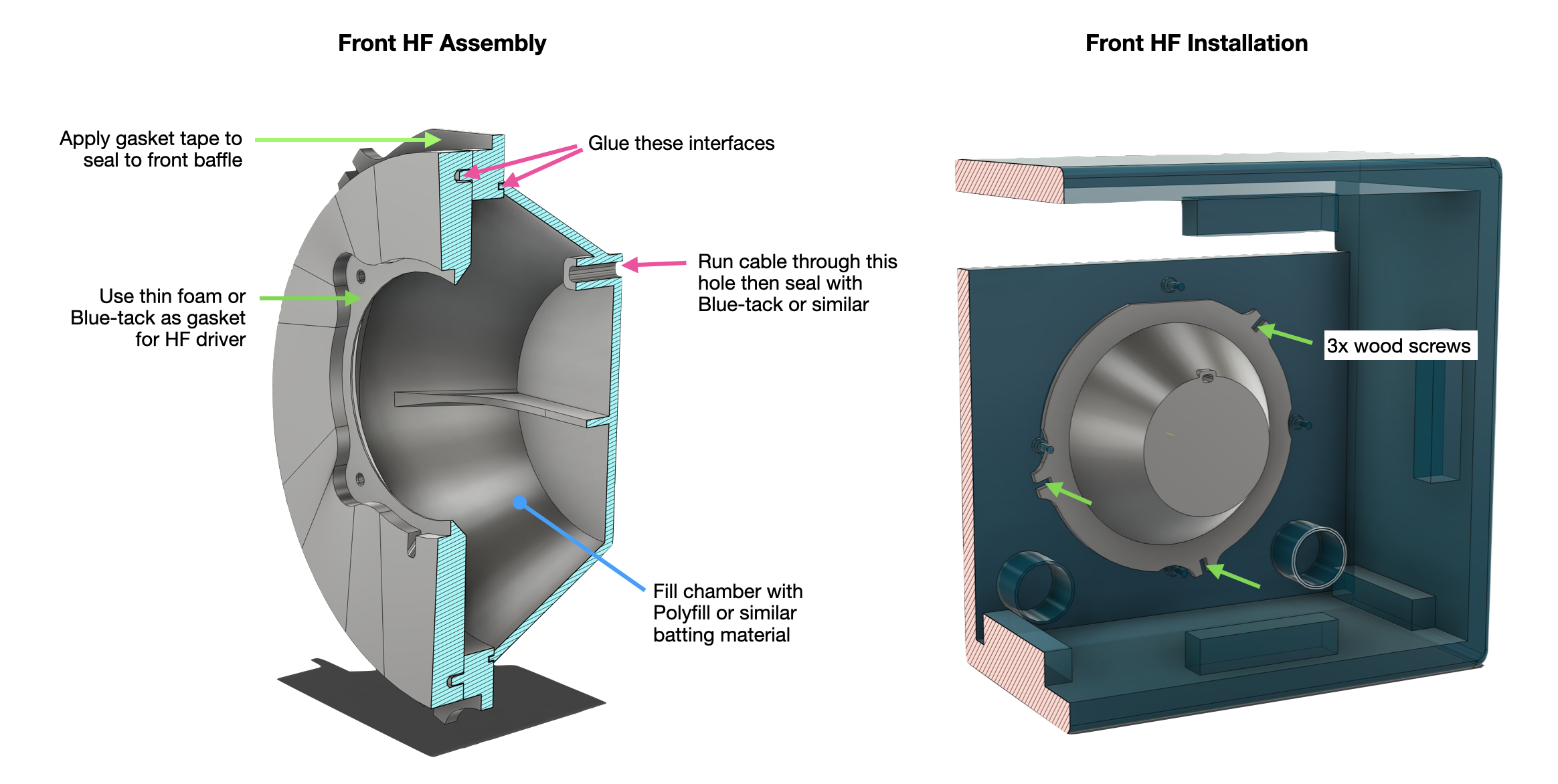
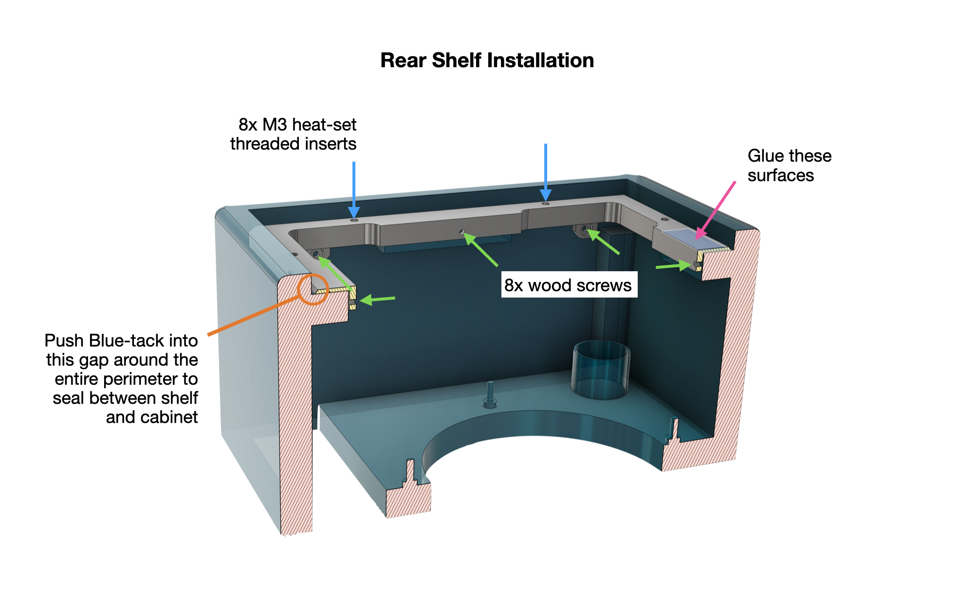
This is where the design stops being a plan and turns into a physical thing you can seal, wire, and screw shut. Almost everything inside the cabinet that isn't a driver or a circuit board is 3D printed: the two sealed HF enclosures, the internal partition that carves out the control cavity, the whole rear panel with its ported woofer mount, the plugs for the original front ports, and all the brackets and covers that hold it together. Most of these parts are doing two jobs at once, locating a component and sealing a volume, which is why the callouts on the figures below are mostly about where glue and gasket tape go. The reasoning behind all that sealing is in Step 5; here I'll walk through the printed parts themselves and how they assemble, and let the labeled figures carry the fine detail.
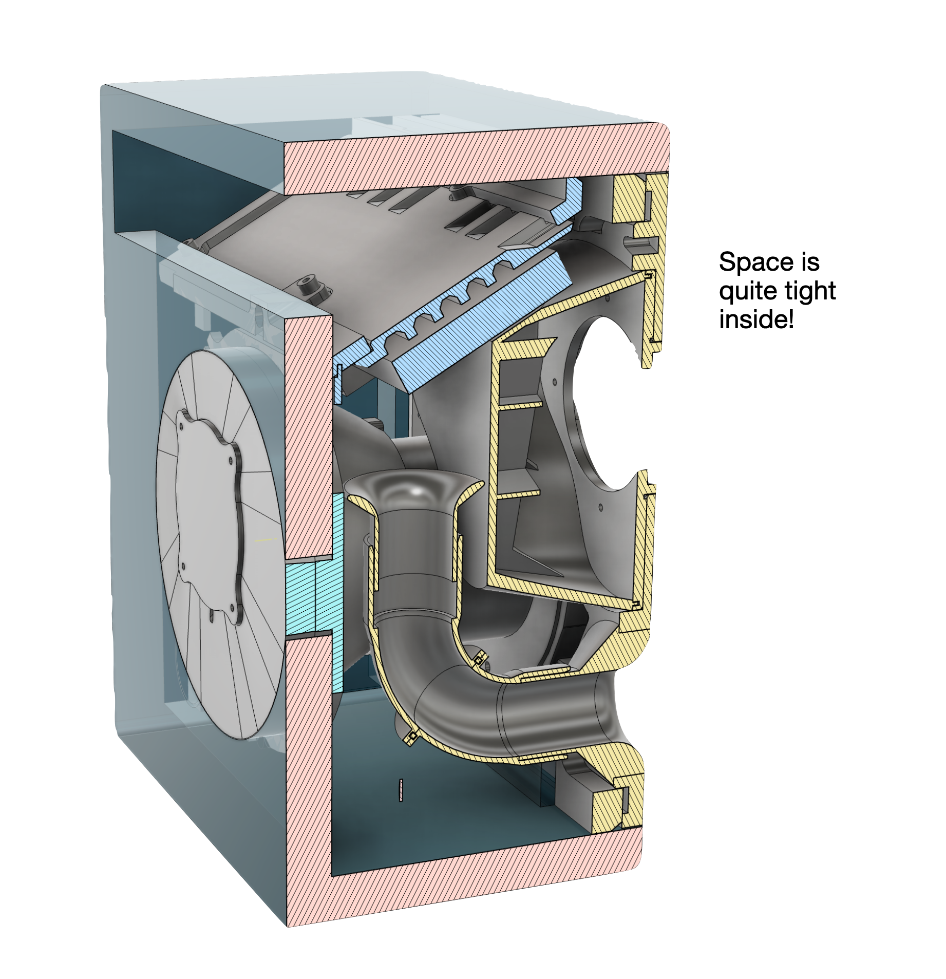
The thing to understand before anything else is that space is tight. Everything nests around everything else, and the assembly order matters because some parts become unreachable once others are in. I'll go in the order I found worked.
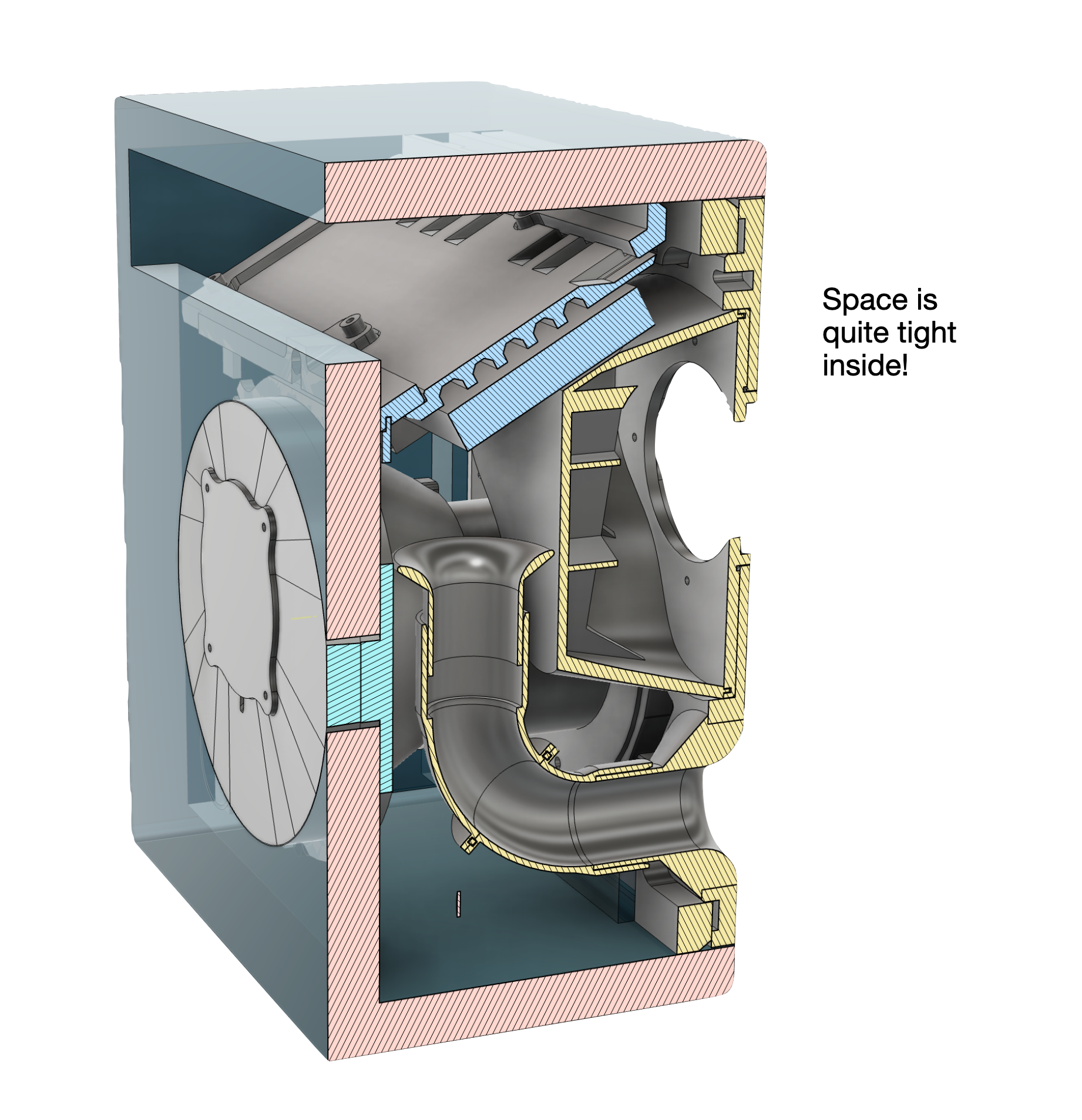
Cross-section of the finished build. The port, both HF enclosures, the woofer, and the electronics cavity all have to share a very small box.
Printing notes. I printed every part in PETG. Use plenty of walls and a high infill, particularly on the HF enclosures and the back panel. Don't be shy with glue on the joints, and a brushed-on coat after assembly can fix any small leaks. Nearly everything mounts with M3 machine screws self-threading straight into printed holes; the exception is the back panel which a heat-set inserts.
The partition and control cavity
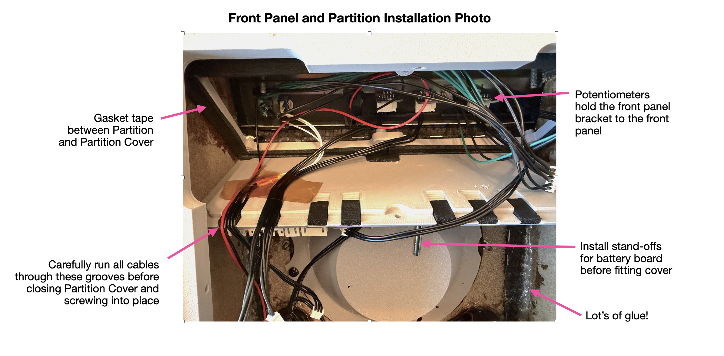
The partition is the part that turns the top corner of the cabinet into a sealed box for the electronics, walling the amplifier and battery board off from the woofer's air volume. Glue along every edge, screw it to the cabinet and then apply additional glue around each edge to seal. Apply a ring of gasket tape around the edge of window in the partition to provide a good seal to the cover.
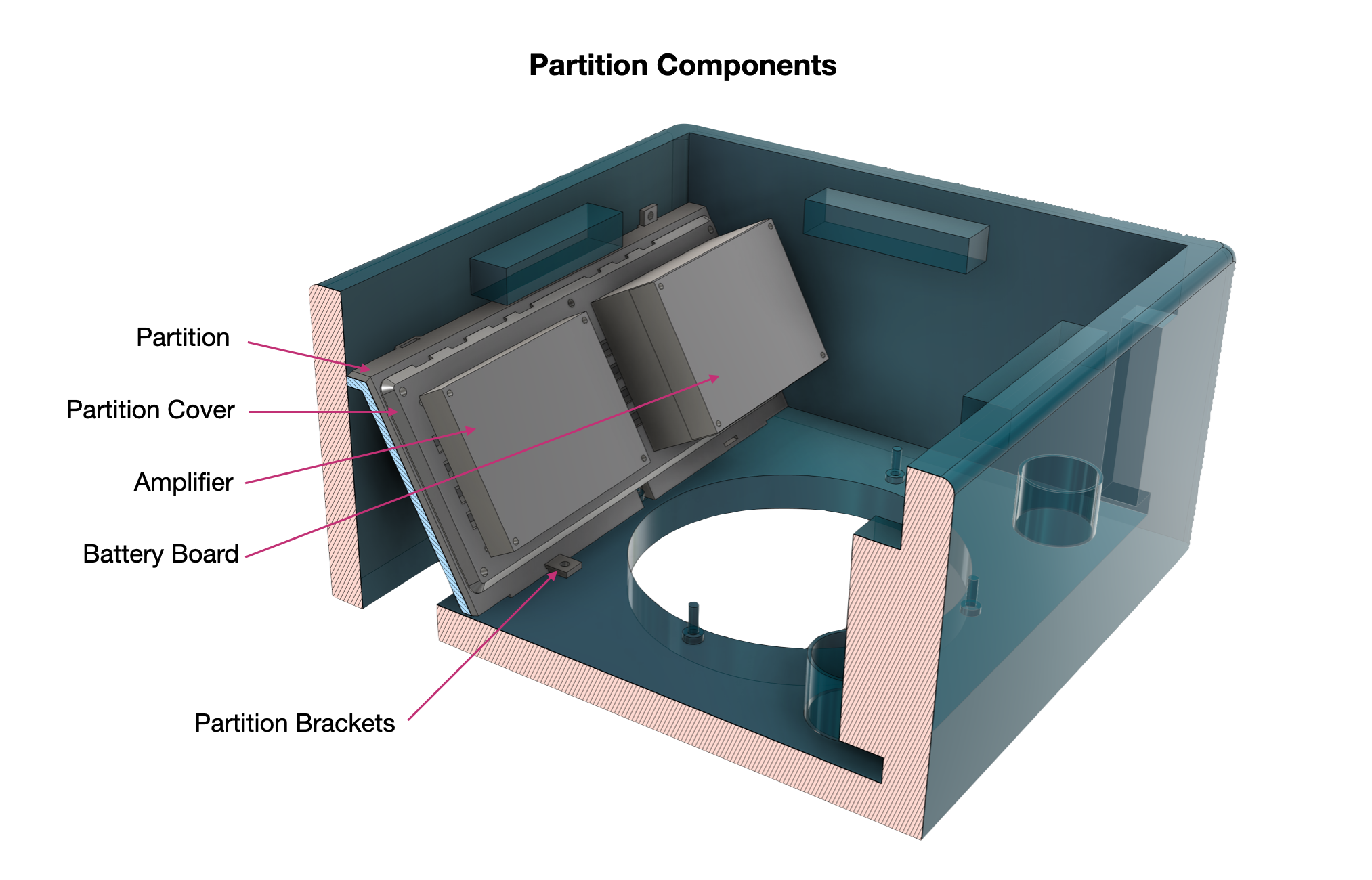
The partition frame and cover, with the amplifier and battery board mounted inside the control cavity.
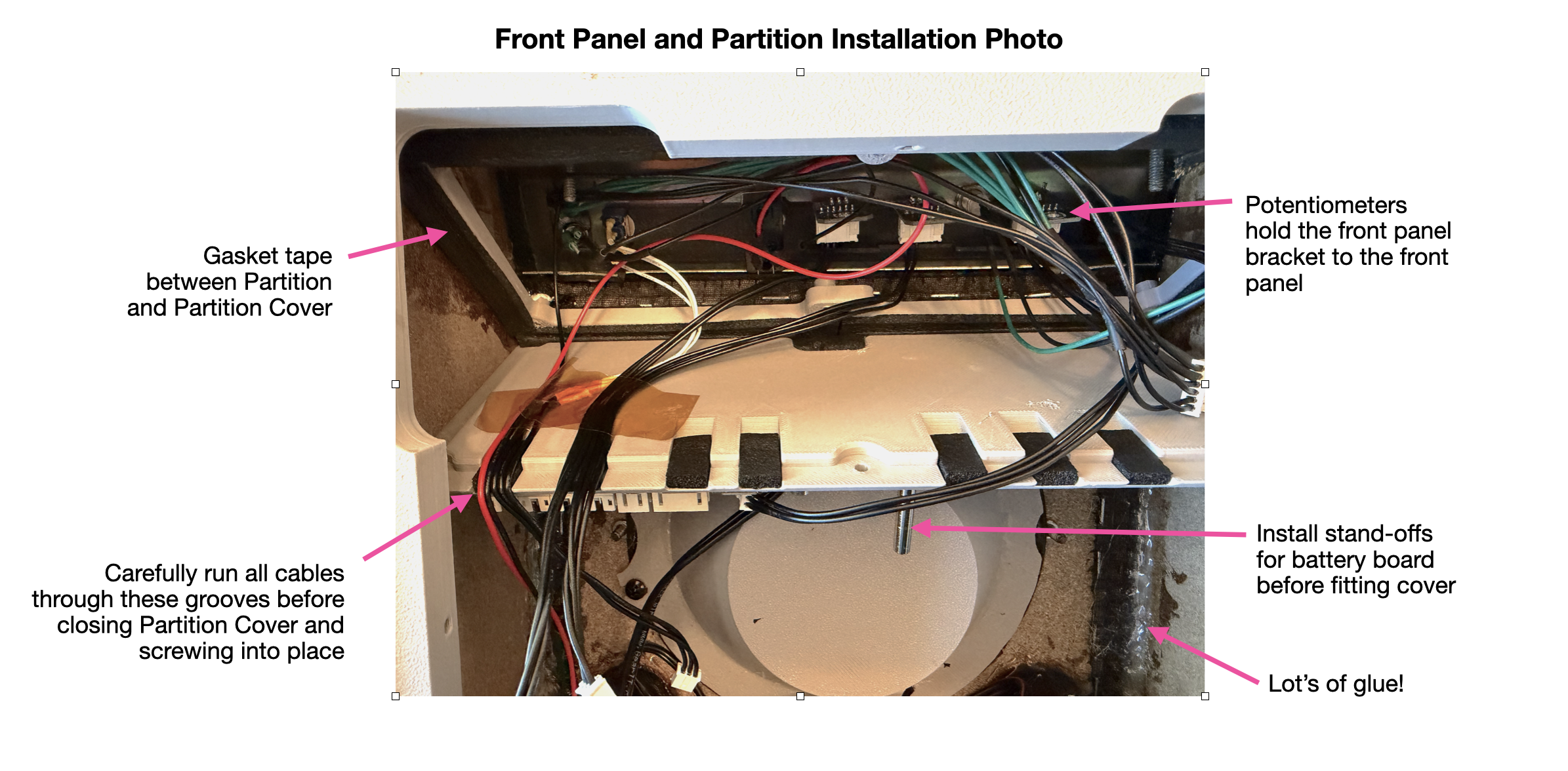
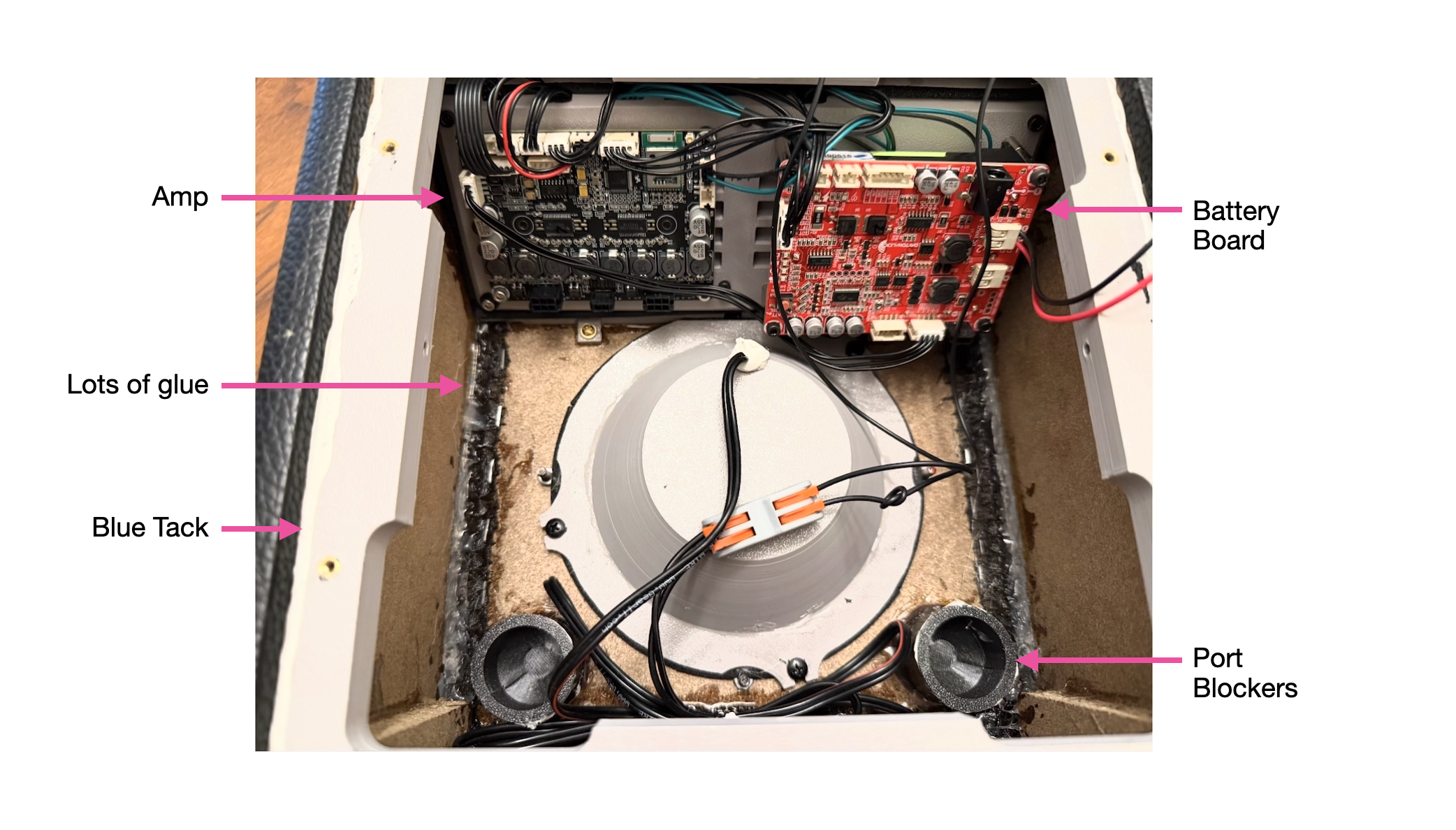
The real thing during assembly: cables dressed through the cover grooves, battery-board stand-offs fitted, and plenty of glue at the seams.
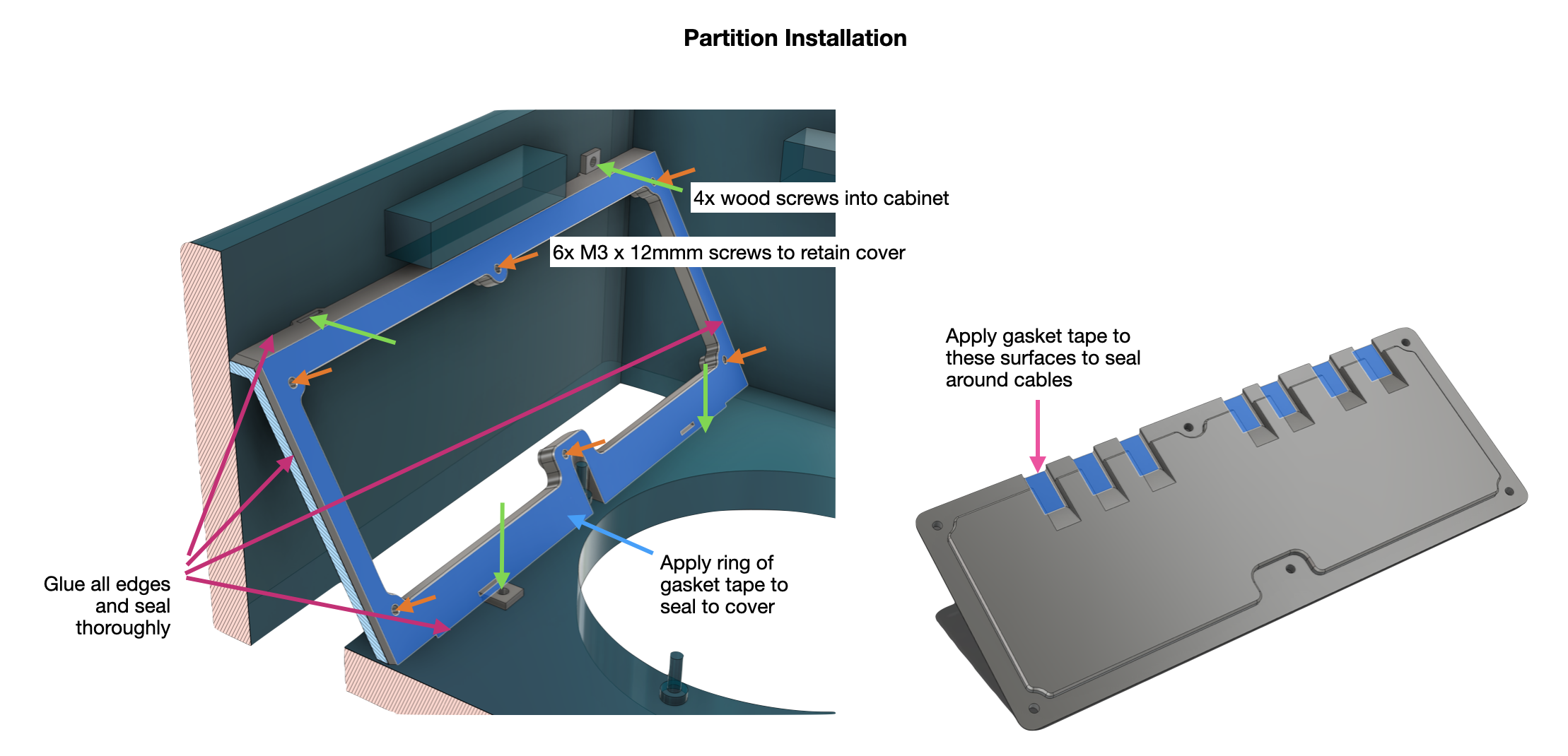
Wood screws fix the frame to the cabinet; M3 screws retain the cover; gasket tape seals the cover and the cable pass-throughs. Glue every edge.
The electronics
The amplifier and battery board screw to the partition cover. M3 stand-offs are required for the battery board, I just used plastic washers for the amp. Note, there is not much clearance between the amp and the rear HF enclosure, so stand-offs might not work for the amp. I fitted stand-offs to the cover before installing it, and then fitted the PCB's to the cover afterwards.
I fitted the panel mount USB-C socket to the side of my cabinet. Make sure the socket you choose can handle the thickness of the walls of your cabinet, and choose the correct size hole-saw for it. I recommend testing the cable with the power supply board before cutting the whole in the cabinet.
The USB-C power supply board is very compact , so I just taped it the the bottom surface of the cabinet. The type I gave a link to has selectable voltage set by a button on it, you just set it once and it remembers the setting until you change it. Selecting 15V or 20V will allow much faster charging than the lower voltages.
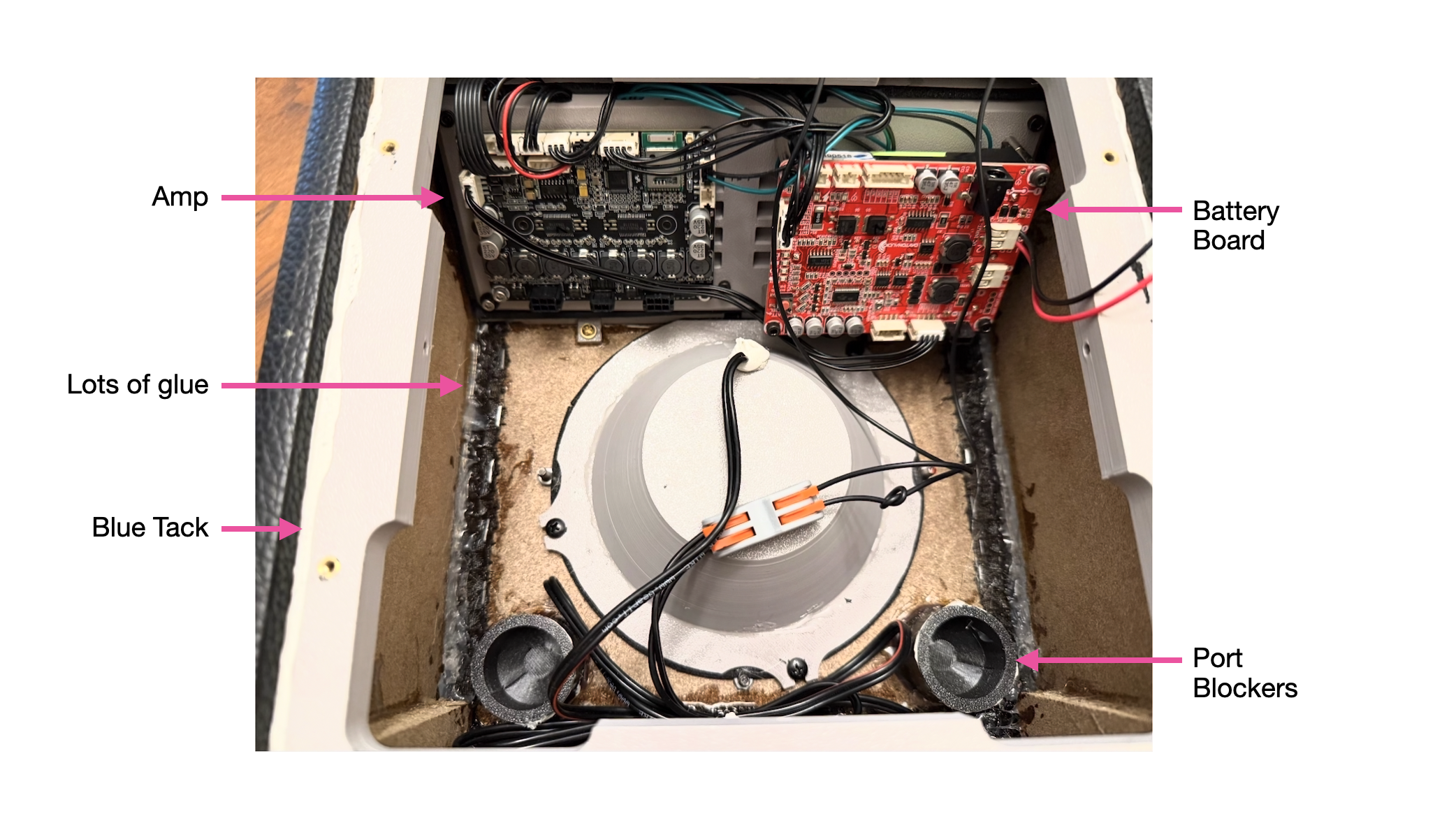
Amp and Battery Board installed on partition
The front HF enclosure
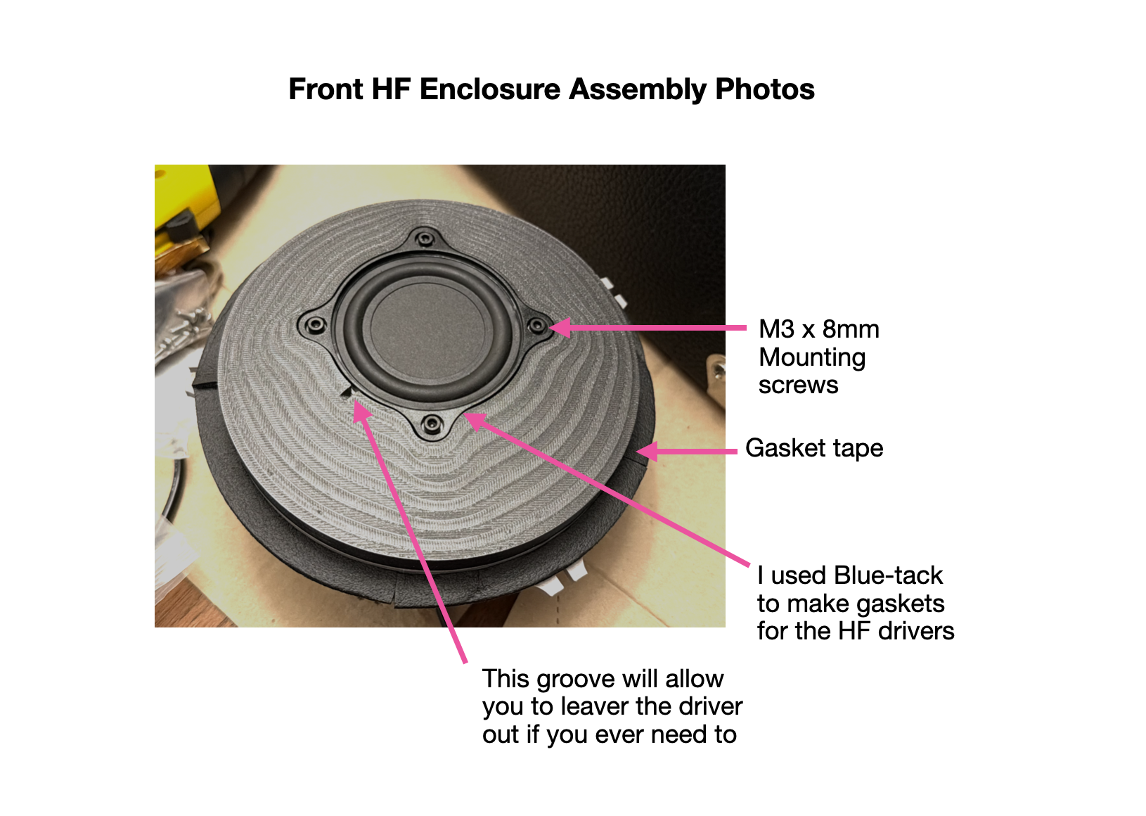
This is the sealed 0.35 L chamber behind the front BMR, the one modeled in Step 4. It prints as a deep cup that bolts to the front baffle over gasket tape, gets stuffed with Polyfill, and has its driver cable sealed where it leaves the enclosure. One detail worth copying: a small groove in the driver seat lets you get a lever under the driver to lift it back out later, which you'll be glad of the first time you want to swap or check it.
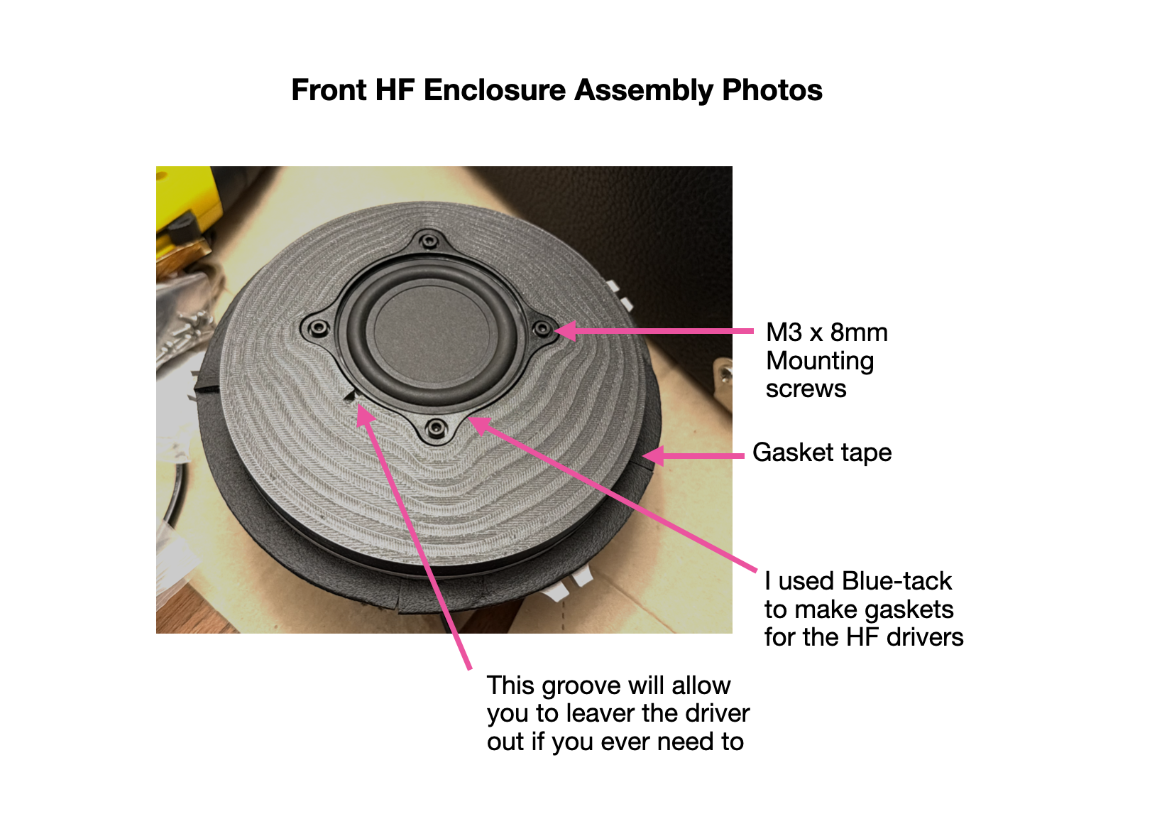
Assembled front HF enclosure. I made the driver gaskets from Blu-tack; note the lever groove at the driver edge.
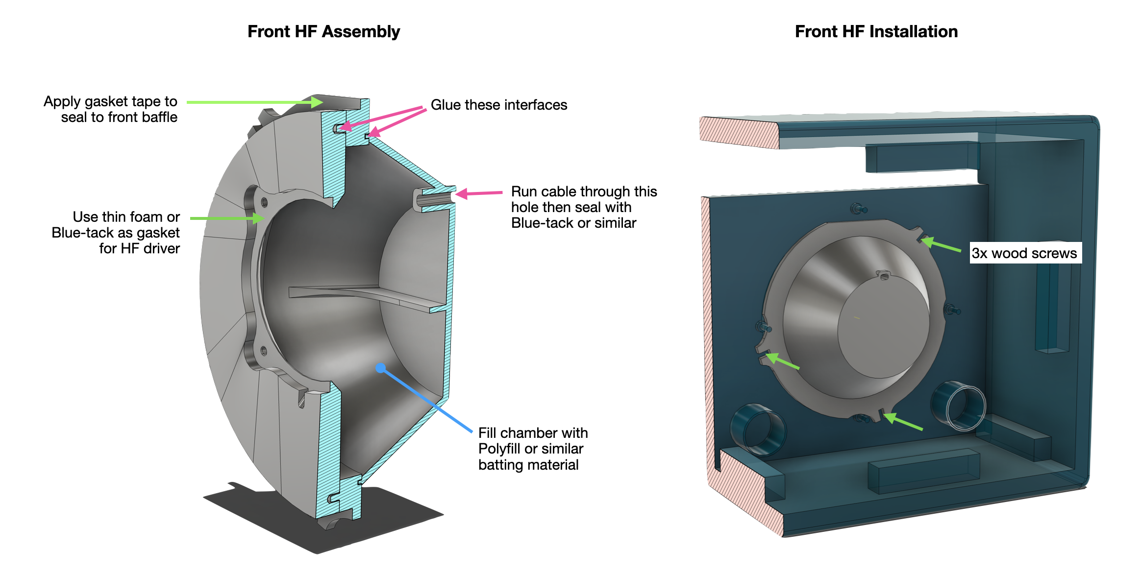
Gasket tape seals the enclosure to the baffle; the cable entry is sealed with Blu-tack; the chamber is filled with Polyfill. Three wood screws hold it in.
The rear panel assembly
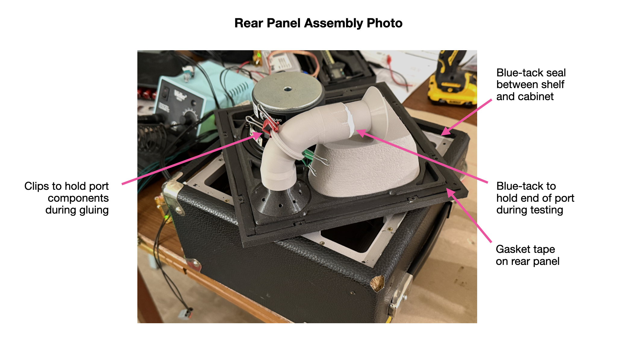
The entire back of the cabinet is replaced with printed parts, the largest prints in the project, and they carry the woofer, the port, and the rear HF enclosure.
First the shelf that the rear panel lands on. It screws to the cabinet and seals to it with a bead of Blu-tack worked into the perimeter gap with a screwdriver. Because the rear panel comes on and off constantly during tuning, the shelf gets heat-set inserts rather than self-threaded plastic, which wouldn't survive the screw cycles.
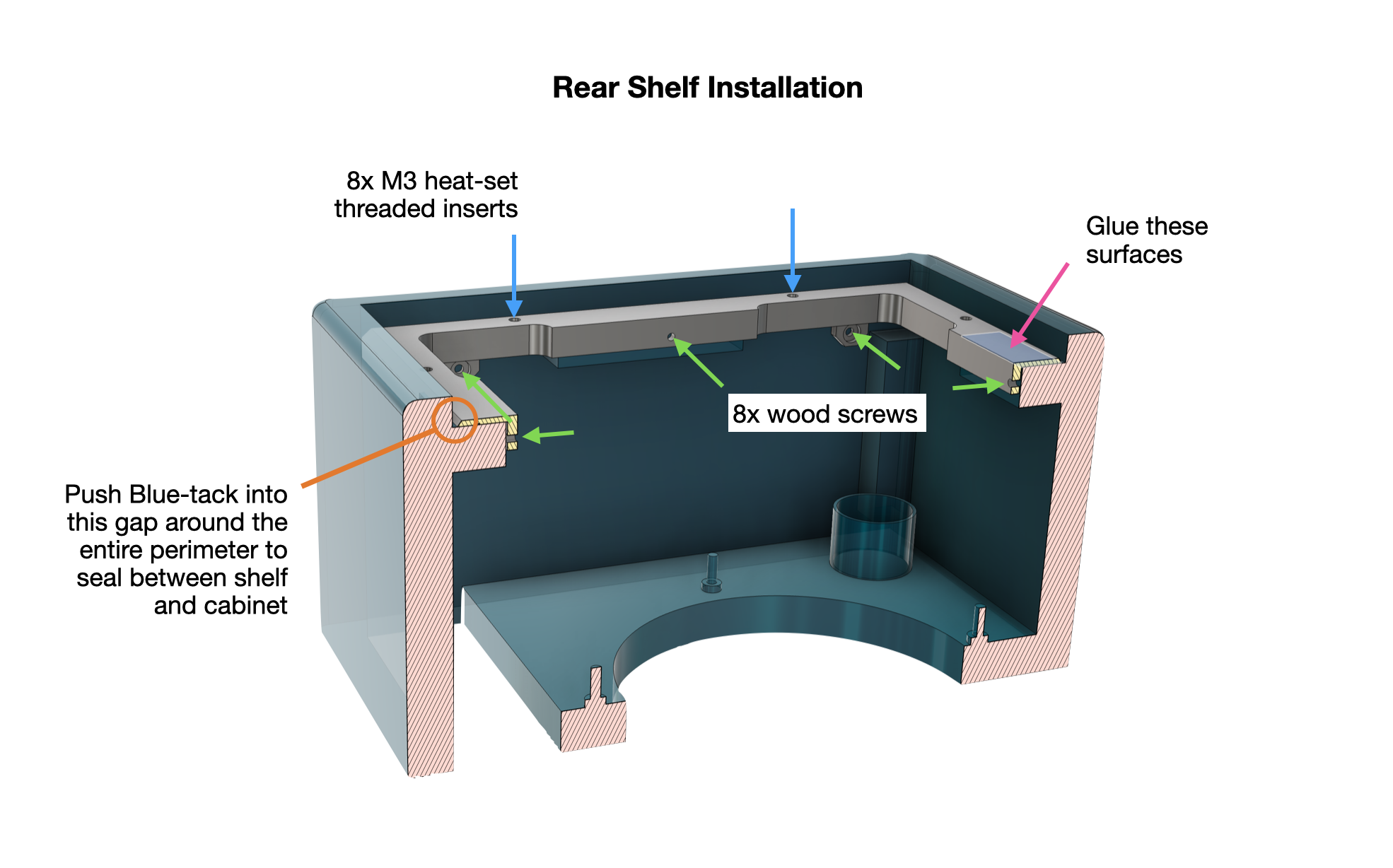
The shelf: wood screws into the cabinet, glued mating surfaces, heat-set inserts for the panel screws, and a Blu-tack seal all round the perimeter gap.
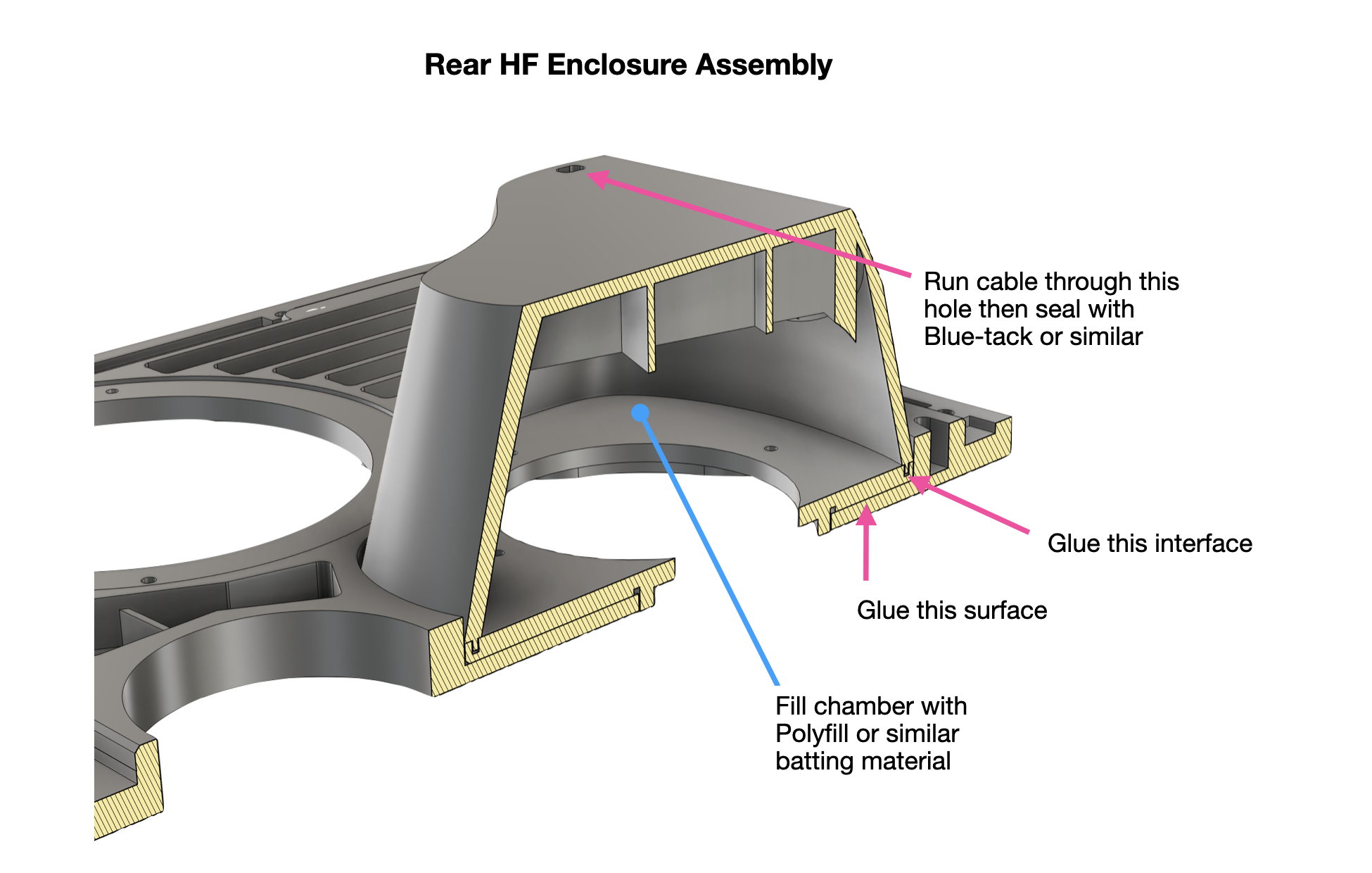
The rear HF enclosure is similar to the front one, sealed and stuffed the same way, sitting on the rear baffle.
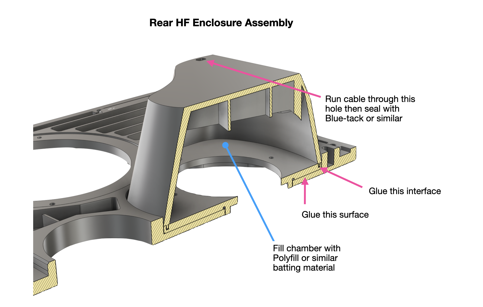
Rear HF enclosure: glued interfaces, a sealed cable entry, and a Polyfill fill, exactly as on the front.
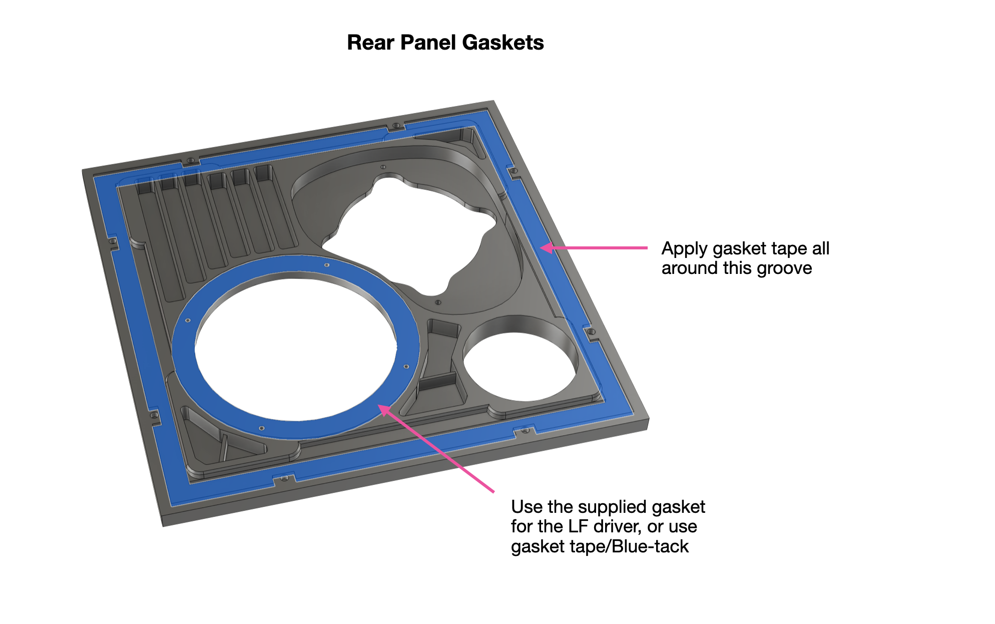
The rear panel itself has a gasket groove running around its whole perimeter and a seal for the woofer, so it lands airtight on the shelf.
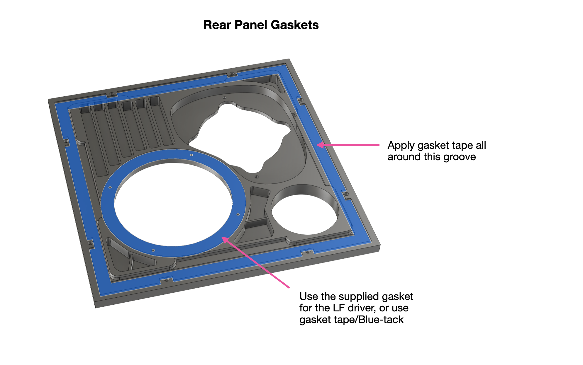
Gasket tape goes in the perimeter groove; the woofer seals with its supplied gasket, or with gasket tape or Blu-tack.
The port, and tuning it
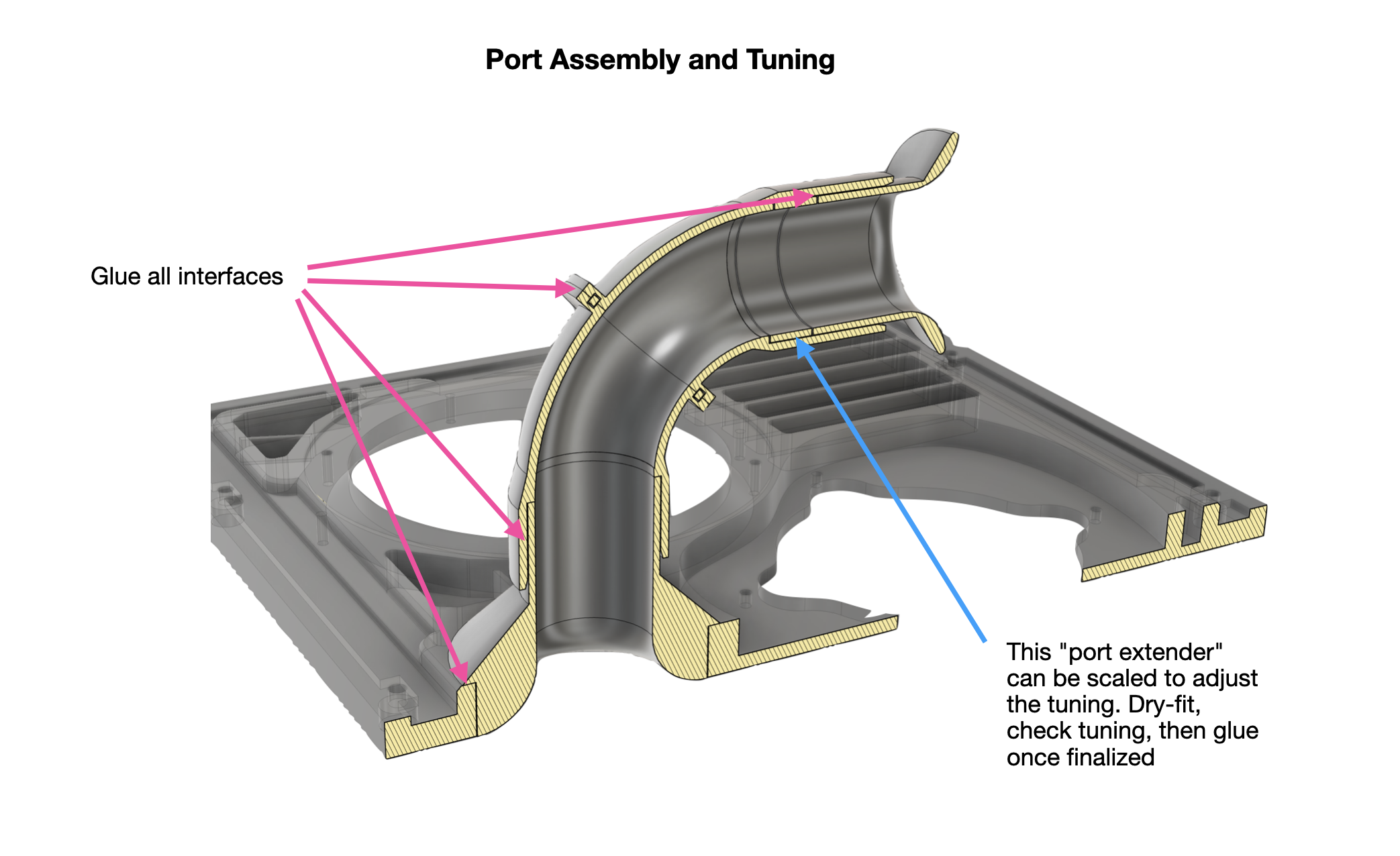
The port is a multi-part printed assembly, a curved tube routed to fit the tight space, and it's the one piece you tune rather than simply fit. The last segment is a "port extender" you can scale in CAD to move the tuning frequency up or down. Dry-fit the whole thing, measure where the box is actually tuned (the impedance method from Step 4), adjust the extender length, and only glue it once you're happy with the tuning.
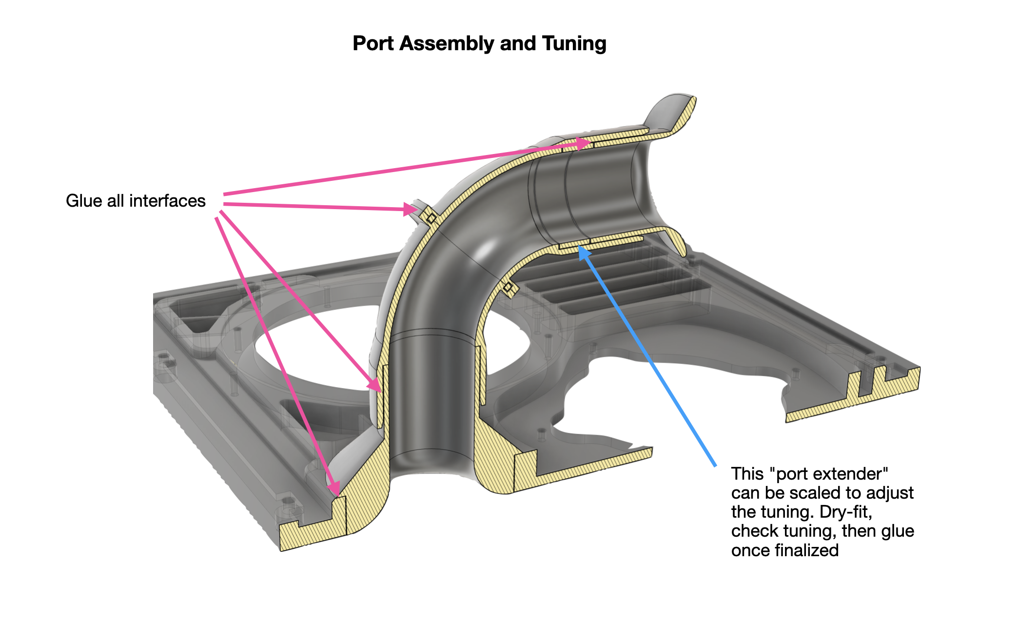
The bass reflex port. Glue every interface once finalized
Rear driver guards
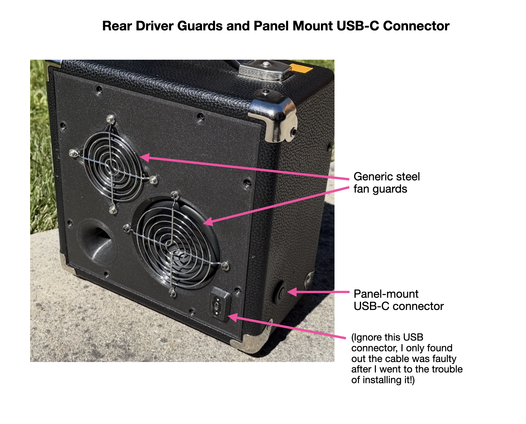
I fitted steel guards over the rear drivers. These are the generic chrome wire ones sold for PC cooling fans. The rear woofer takes a 92 mm guard and the rear BMR an 80 mm one.
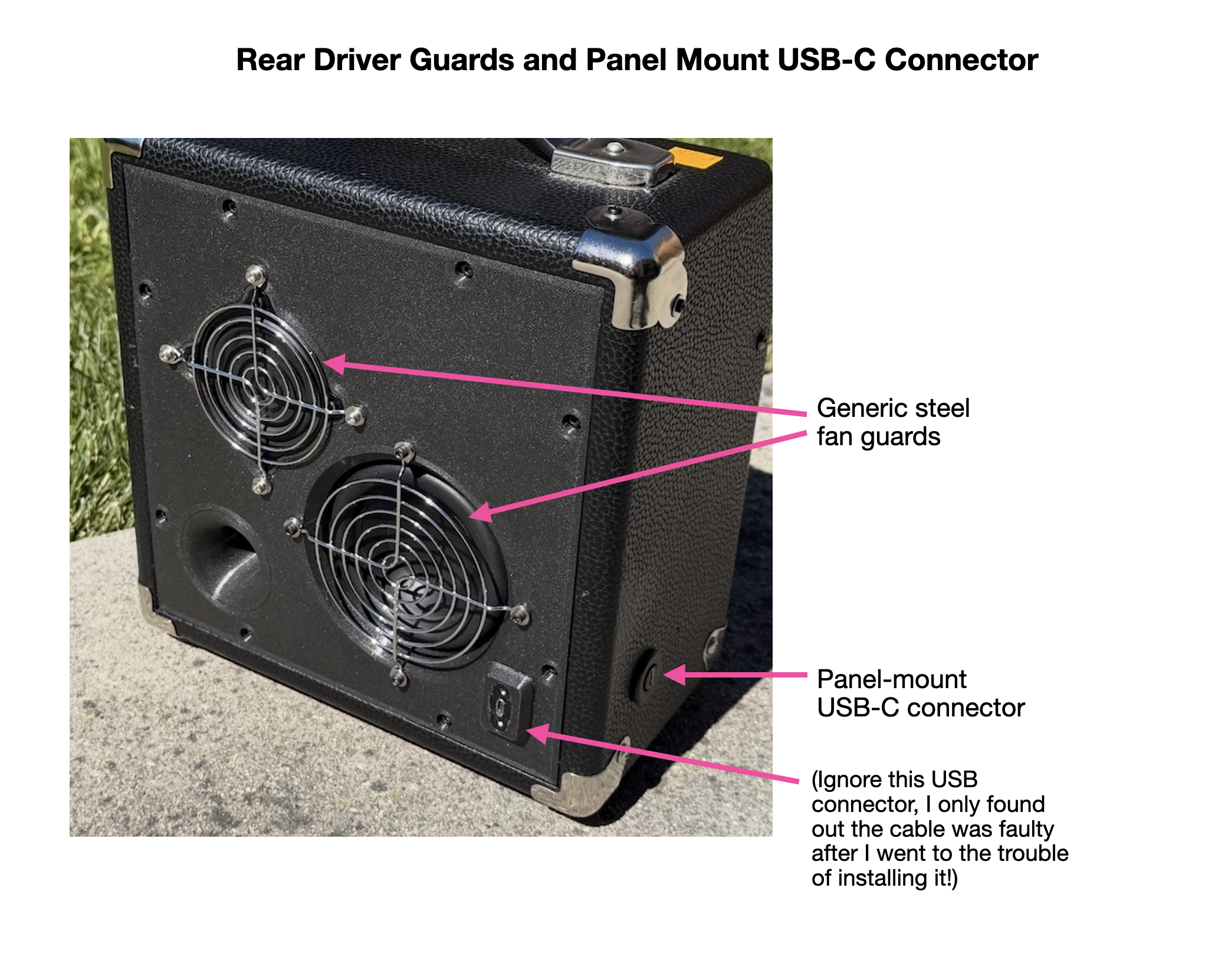
The two rear-firing drivers and the panel-mount USB-C charging socket on the side.
Blocking the original front ports
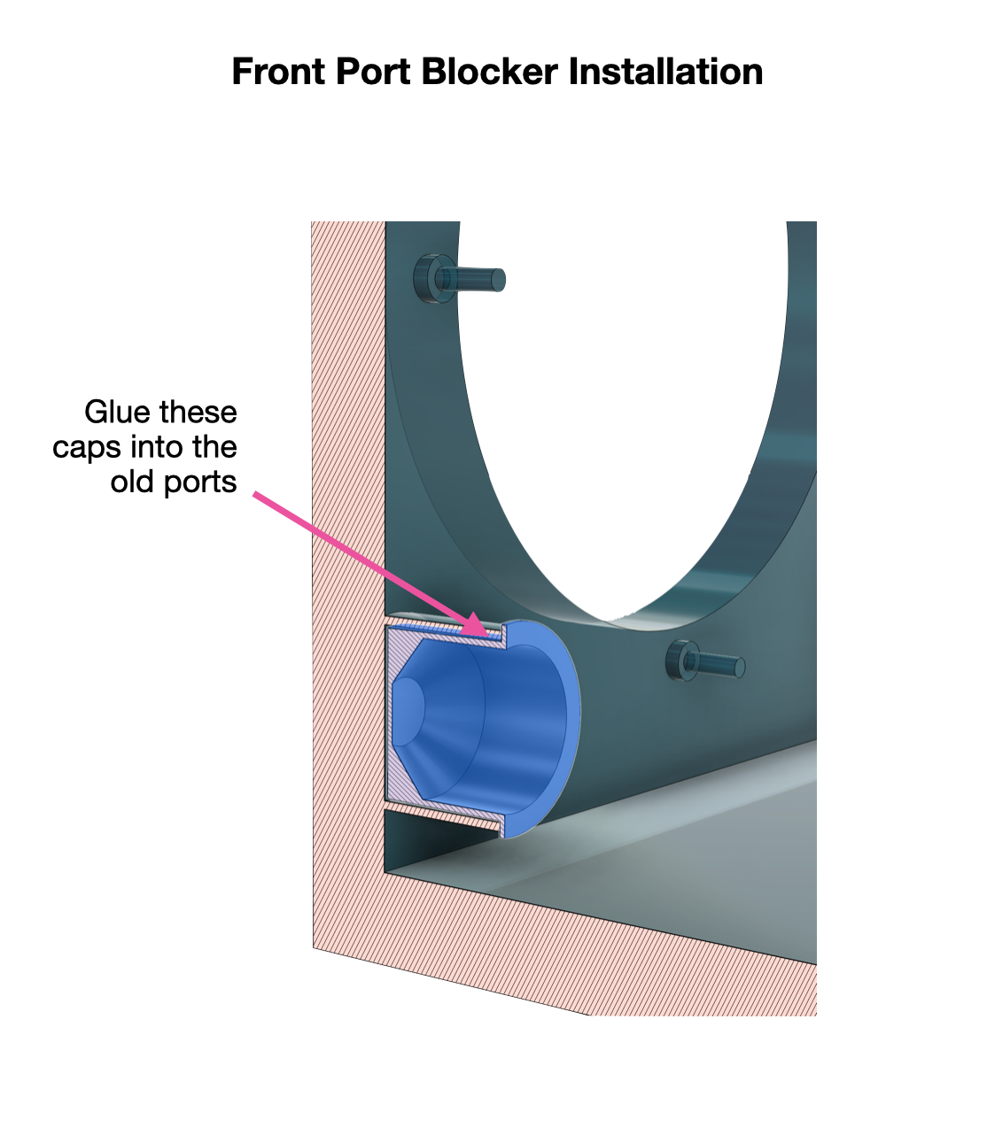
The 10G's front baffle still has its original reflex ports, which have no place in the new design. They get printed caps glued into them.
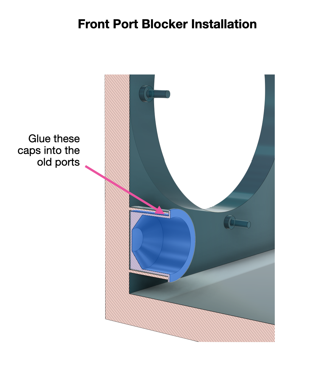
Printed caps glued into the original front ports.
The front control panel
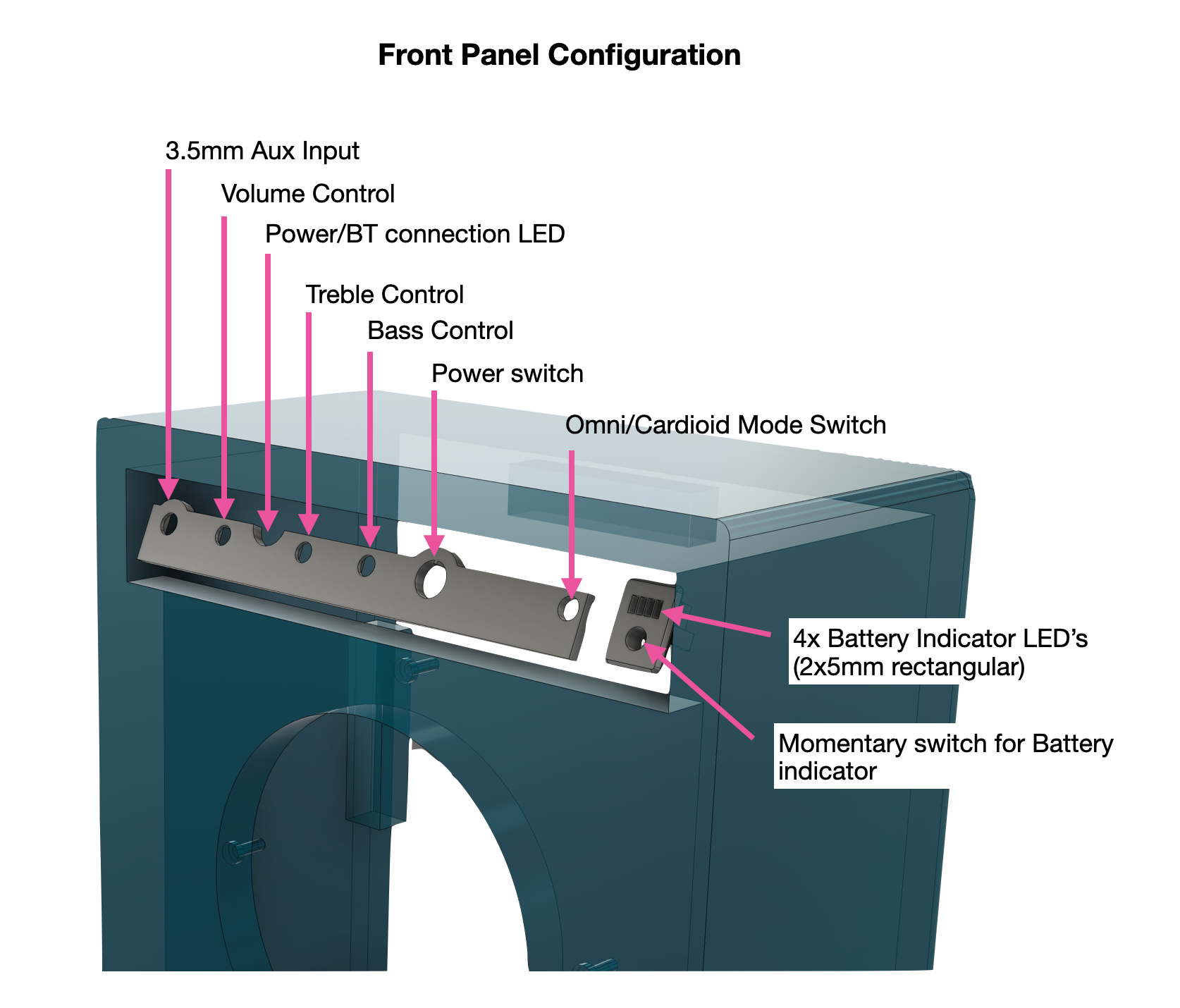
The original control-panel opening is reused for the new controls, which mount on a printed bracket that the potentiometers themselves clamp to the panel. Left to right it carries the 3.5 mm aux input, the volume control, the power / Bluetooth-connection LED, the treble control, the bass control, the power switch, and the omni/cardioid mode switch, with a small battery-level indicator (four rectangular LEDs and a momentary button that wakes it) off to one side. The battery indicator arrives as a ready-made harness with the battery board, and you can fit it as supplied; I only swapped its round LEDs for rectangular ones and used a smaller button so everything sat neatly in this panel.
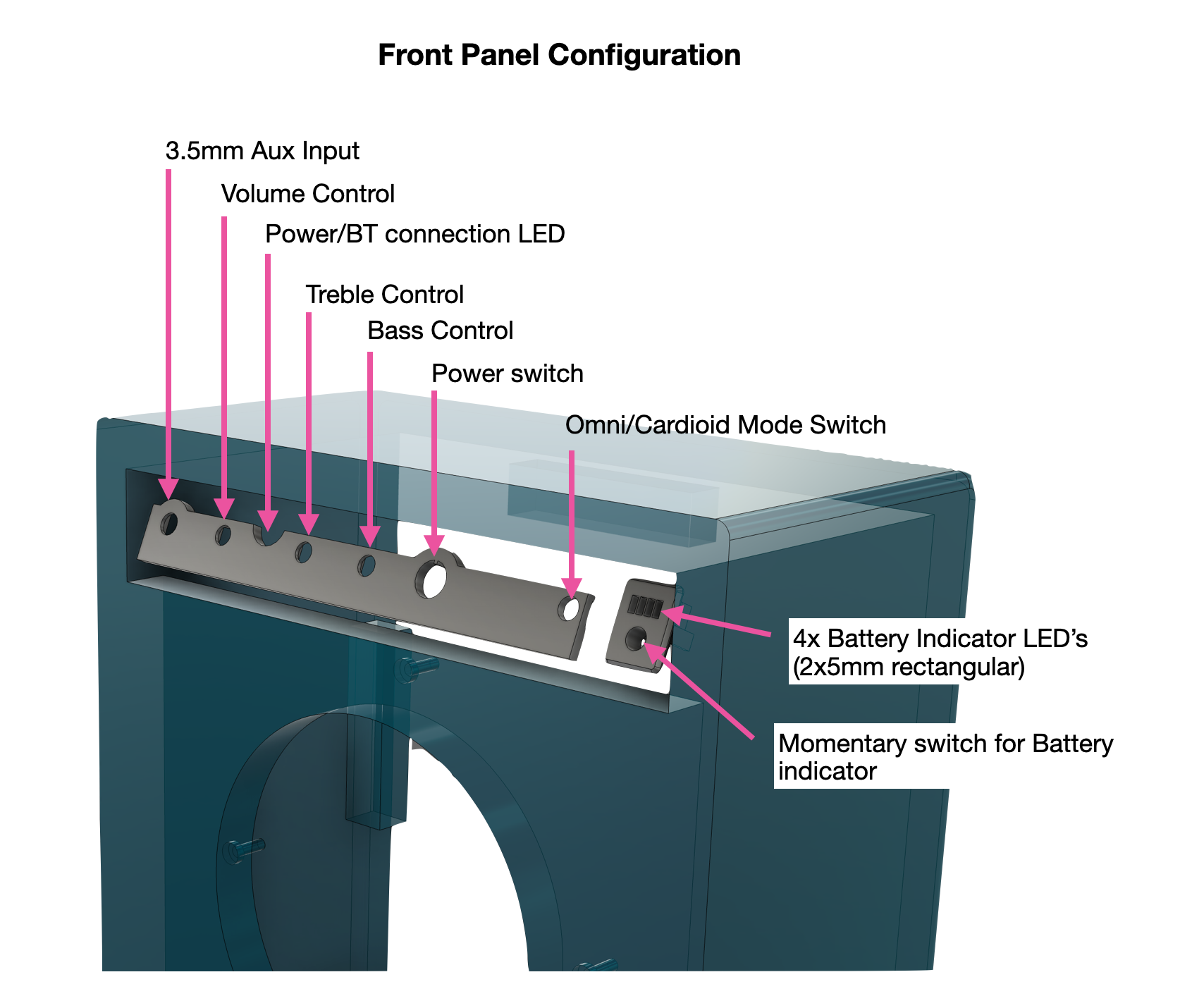
The control layout in the reused panel opening.
Files included
The STL files print directly. The STEP file opens in any CAD package if you want to modify a part without Fusion 360, and the Fusion 360 archive is the native model.
Downloads
Electronics & Power
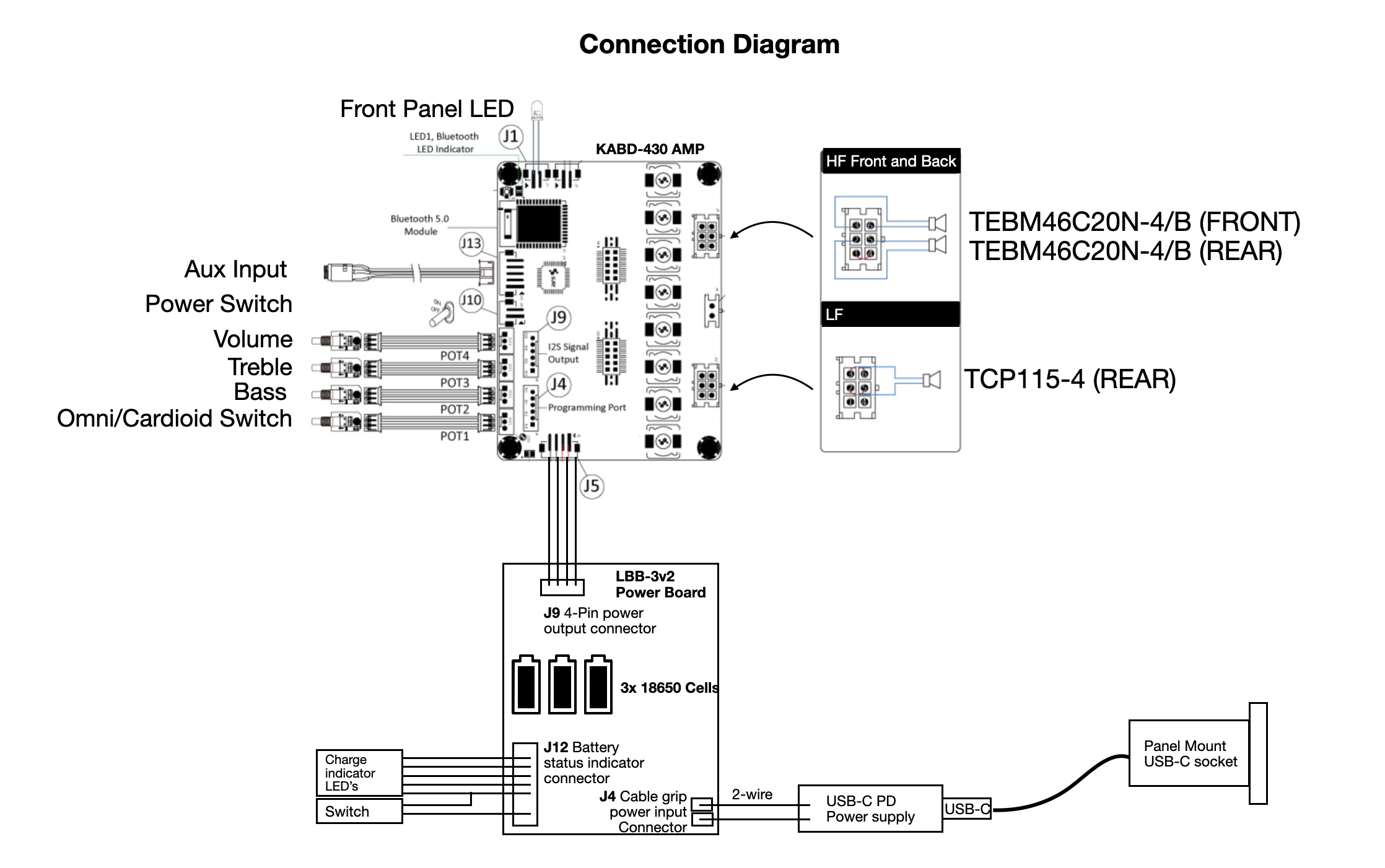
The electronics package is almost entirely Dayton Audio's portable-speaker ecosystem, and that's a deliberate choice: the boards are designed to plug into each other with pre-made harnesses, which turns the electrical build into an assembly job rather than a fabrication one. Soldering is nearly optional in this project. Here's what each piece does and why it earned its place.
The amplifier: Dayton Audio KABD-430. This board is the heart of the build — a 4 × 30 W Class D amplifier, a Bluetooth 5.0 receiver (with aptX HD), and the ADAU1701 DSP that runs everything in Step 8, all on one board. The integration is the point: the Bluetooth module feeds the DSP digitally over I2S, the DSP feeds the amplifiers, and the whole signal path exists on one PCB with no interconnects to build or hum loops to chase.
The channel arithmetic works out neatly. This design needs three amplified channels: woofer, front BMR, rear BMR. A four-channel board sounds like one channel wasted, but the KABD-430's output stages can be bridged in pairs — a jumper on the speaker harness — so the spare channel pairs up with another to make a single 60 W channel. That bridged pair drives the woofer, which is exactly where the extra power belongs: the bass section is doing the hardest work, especially with the boost engaged, while the BMRs coast on 30 W each. It's also why the 4 Ω versions of all three drivers got the job — the board is rated stable down to 4 Ω, and bridging wants the load impedance you can give it. One practical note: the DSP is programmed through a separate USB programmer board (Dayton's ICP1 or KPX) that connects to the amp during development and comes off when you're done — budget for one if you're building this, since without it the DSP is a locked box.
The control panel plugs straight into this board too. The KABD series exposes four 3-pin headers, each carrying a supply, ground, and one of the ADAU1701's multipurpose ADC pins — these are the auxiliary ADC inputs the tone controls and mode switch in Step 8 read. The pots and switch on the front panel wire to these headers and nothing else. No microcontroller, no extra ADC board; the DSP reads the knobs directly.
The battery: Dayton Audio LBB-3v2 with three 18650 cells. The KABD boards have no charging circuit of their own, so the battery board has to bring its own charge management and protection — which the LBB-3v2 does, and it's the board Dayton specifically pairs with the KABD series. Three cells in series give a nominal 11.1 V, right at the bottom of the amp's 12–24 V range.
This was a considered trade rather than an obvious pick. The five-cell LBB-5Sv2 would supply 21 V, and Class D amplifiers make more power from more voltage — the headline 30 W and 60 W figures assume the upper end of the supply range, and on a 3-cell supply the real ceiling is lower. But the five-cell board plus cells wouldn't fit in the control cavity without significant surgery, and battery life at sane listening levels is excellent on three cells. So the choice came down to space, power, and runtime, in that order of constraint. If your donor cabinet has more room, the five-cell board is the easy upgrade — nothing else in the design changes. And this is part of why the dynamic bass limiter earns its keep: the system is engineered to make the most of a modest power budget rather than pretending it has an infinite one.
Charging: USB-C, without modernizing the looks. Charging comes in through a panel-mount USB-C socket, which connects internally to a short lead ending in a male USB-C plug. That plugs into a generic USB-C power supply board (the kind sold for retrofitting battery-powered devices) which negotiates with whatever USB-C charger you connect and delivers the DC the battery board wants. The result: the speaker charges from the same charger as your laptop or phone, and the only visible modification is a single small socket. No barrel jacks, no dedicated wall wart to lose.
The cable kits. Two of Dayton's harness kits — the LBB-5CL for the battery board and the KABD-SPF for the amplifier — provide every interconnect pre-terminated. Between them, the power path, speaker connections, and control headers all plug together. This is what demotes the soldering iron to "optional" in the equipment list.
The front panel. Almost everything on the front panel is the cable kits again, plugged straight in. The volume, treble, and bass pots and the mode switch land on the KABD's four 3-pin ADC headers described above, and the DSP reads them directly. The 3.5 mm aux input came as part of the cable kit and there was a spare spot for it on the panel, so it went in, giving a wired input alongside Bluetooth. The battery-level indicator is more of the same: it comes as a complete pre-wired harness with the LBB battery board, four LEDs and a little momentary button that wakes them, and in most builds you can fit it exactly as supplied. I only changed it to suit the panel, swapping the round LEDs for rectangular ones and the button for a smaller one so it sat neatly in the available space. I also had room for one more LED after the battery indicators, so I wired in the KABD's Bluetooth-status LED on its unmodified kit cable. It glows steady when a device is connected and flashes when nothing is paired, so with the amp powered it doubles as a power light and a pairing indicator, which is why it earned the last slot.
A word on battery safety. This is lithium cells inside a wooden box with an amplifier — treat it with appropriate respect. Use quality name-brand 18650s from a reputable supplier (the market is thick with re-wrapped junk), mount the board and cells securely so nothing can chafe or short when the speaker gets carried around. Mounting details are in Step 5.
The DSP — Where the Magic Lives
a. Overview
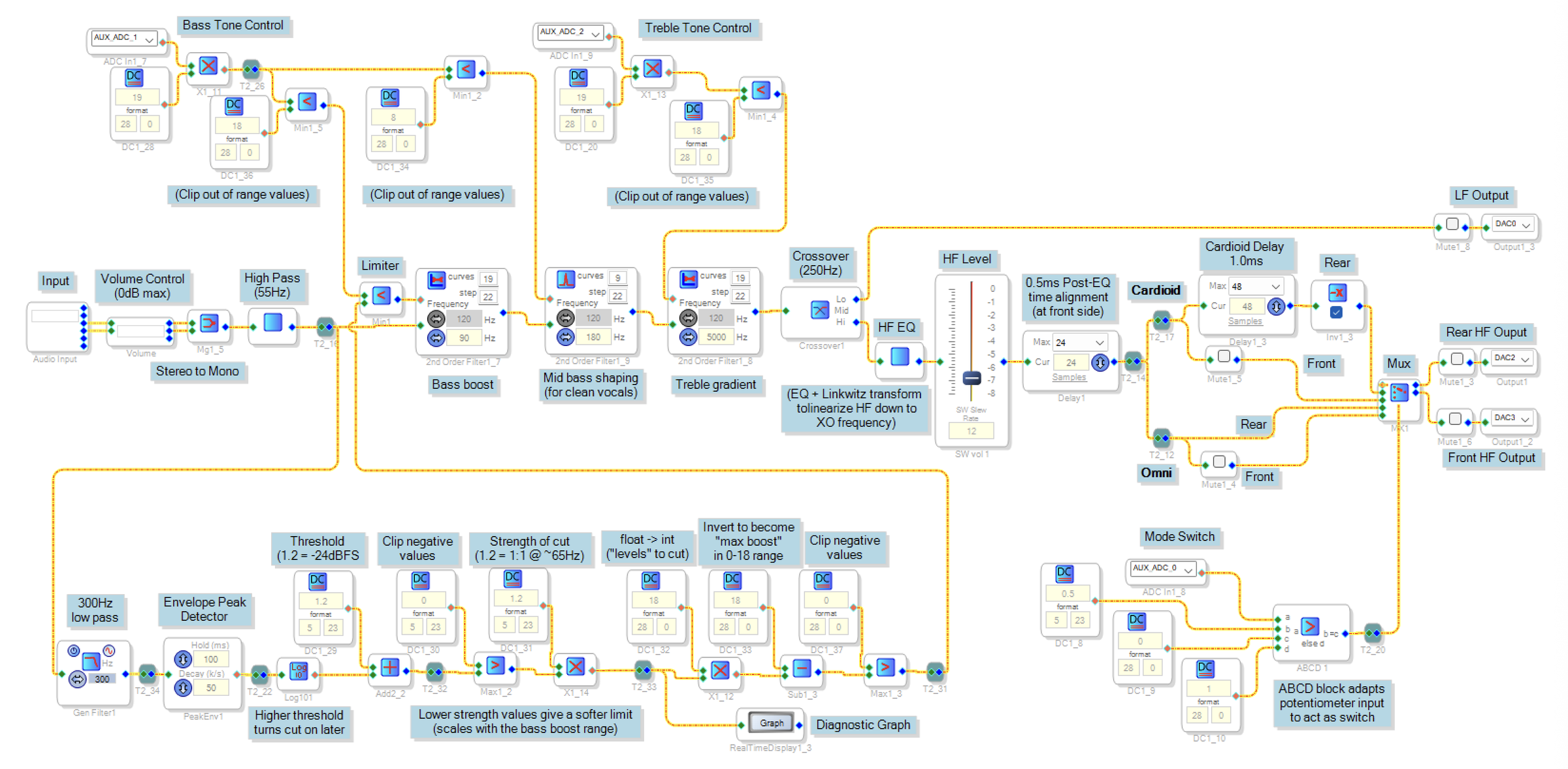
The whole design runs on the ADAU1701 DSP built into the KABD-430, programmed with Analog Devices' free SigmaStudio tool. SigmaStudio is graphical: you drag processing blocks onto a canvas, wire them together, and download the result to the board. The full design looks intimidating at first glance, but it breaks into three clean layers.
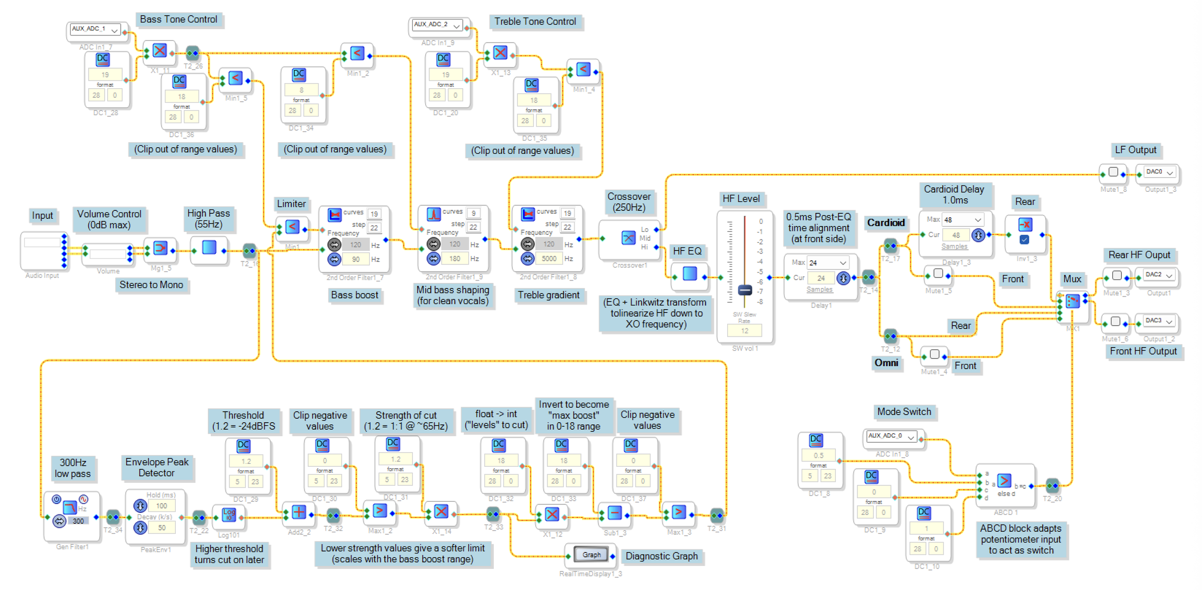
The whole DSP Block Diagram (screenshot from SigmaStudio)
The audio path. Following the signal from left to right: the stereo Bluetooth input passes through a volume control and is mixed down to mono. (A single speaker gains nothing from stereo, and mono means every listener around an omnidirectional speaker hears the same thing.) The mono signal then passes through three tone-shaping filter banks in series: the bass boost shelf, a mid-bass shaping filter, and the treble gradient. After tone shaping comes a 55 Hz high-pass filter that protects the port, then the 250 Hz Linkwitz-Riley crossover that splits the signal into its low and high frequency ranges. The low band goes straight to the woofer's amplifier channel. The high band gets an EQ stage that linearizes the BMR's response down to the crossover frequency, a level trim to match the HF section's sensitivity to the woofer's, and a 0.5 ms delay that time-aligns the front BMR with the woofer. Finally the HF signal splits into the front and rear driver feeds, where the omni/cardioid mode selection happens: in omni mode both drivers get the same signal, in cardioid mode the rear driver's copy is delayed by 1 ms and inverted.
The control layer. Three potentiometers and their wiring are the entire user interface, read through the DSP's auxiliary ADC inputs. The trick that makes the tone controls work is the *index selectable filter*: a filter block holding a whole family of pre-computed response curves, with a control input that picks which curve is live. The bass control indexes through 19 low-shelf curves, the treble control through 19 high-shelf tilts, and the DSP smoothly interpolates between adjacent curves as the knob turns, so there are no clicks or steps. The mode switch is the same idea taken further: a threshold block turns a pot into a two-position switch that flips the HF routing between omni and cardioid. Nothing in the control layer touches the audio directly; it just steers coefficients.
The limiter sidechain. Running along the bottom of the design is the dynamic bass limiter, the part of this project I think is most worth borrowing. It taps the signal after the volume control, low-pass filters it at 300 Hz so it's watching the content the bass boost actually affects, tracks the level with a peak envelope detector, and converts the result through some log-domain arithmetic into a single number: the maximum bass boost the system can currently afford. That number and the bass knob's position feed a minimum block, and the smaller of the two wins. When the signal is quiet the limit is high and the knob has full authority; as the level rises the limit descends and progressively overrides the knob. Sections 8d covers how this works in detail.
b. Crossover & the Cardioid Path
The crossover. The mono signal splits at 250 Hz using SigmaStudio's crossover block set to 48 dB/octave Linkwitz-Riley slopes. The acoustic reasoning is in Step 3; the DSP-side observation is how cheap this is. A 48 dB/octave crossover in the analog world is an heroic undertaking. Here it's a dropdown selection, it costs a modest slice of the instruction budget, and it's exactly repeatable between builds. Steep slopes buy real protection for the small BMRs, so there's no reason to be conservative. Below the crossover, the low band goes straight out to the bridged amplifier channel driving the woofer. A 55 Hz high-pass sits just upstream, keeping content below the port tuning from reaching the driver — that stuff produces no useful output, just excursion and chuffing.
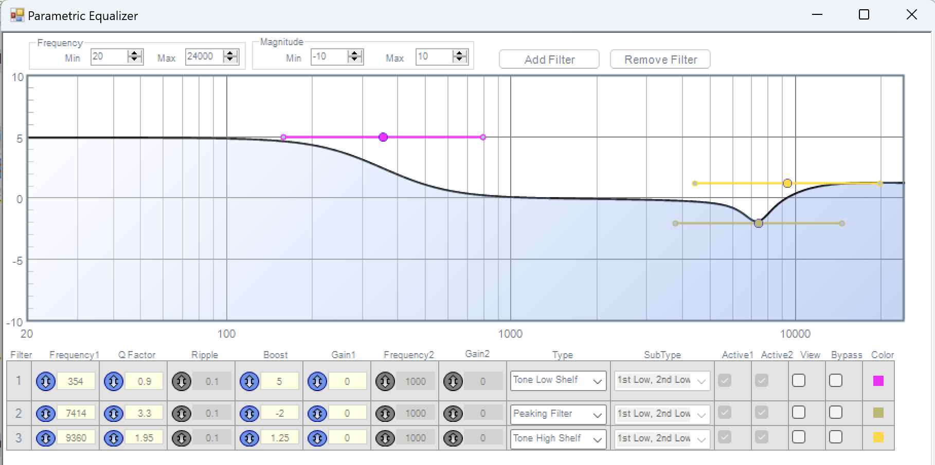
HF equalization. The BMR drivers aren't flat out of the box, especially being asked to run down to 250 Hz, so the high band gets a three-tap parametric EQ ahead of everything else:
| # | Type | Frequency | Q | Gain |
|---|---|---|---|---|
| 1 | Low shelf | 354 Hz | 0.9 | +5 dB |
| 2 | Peaking | 7.4 kHz | 3.3 | −2 dB |
| 3 | High shelf | 9.4 kHz | 1.95 | +1.25 dB |
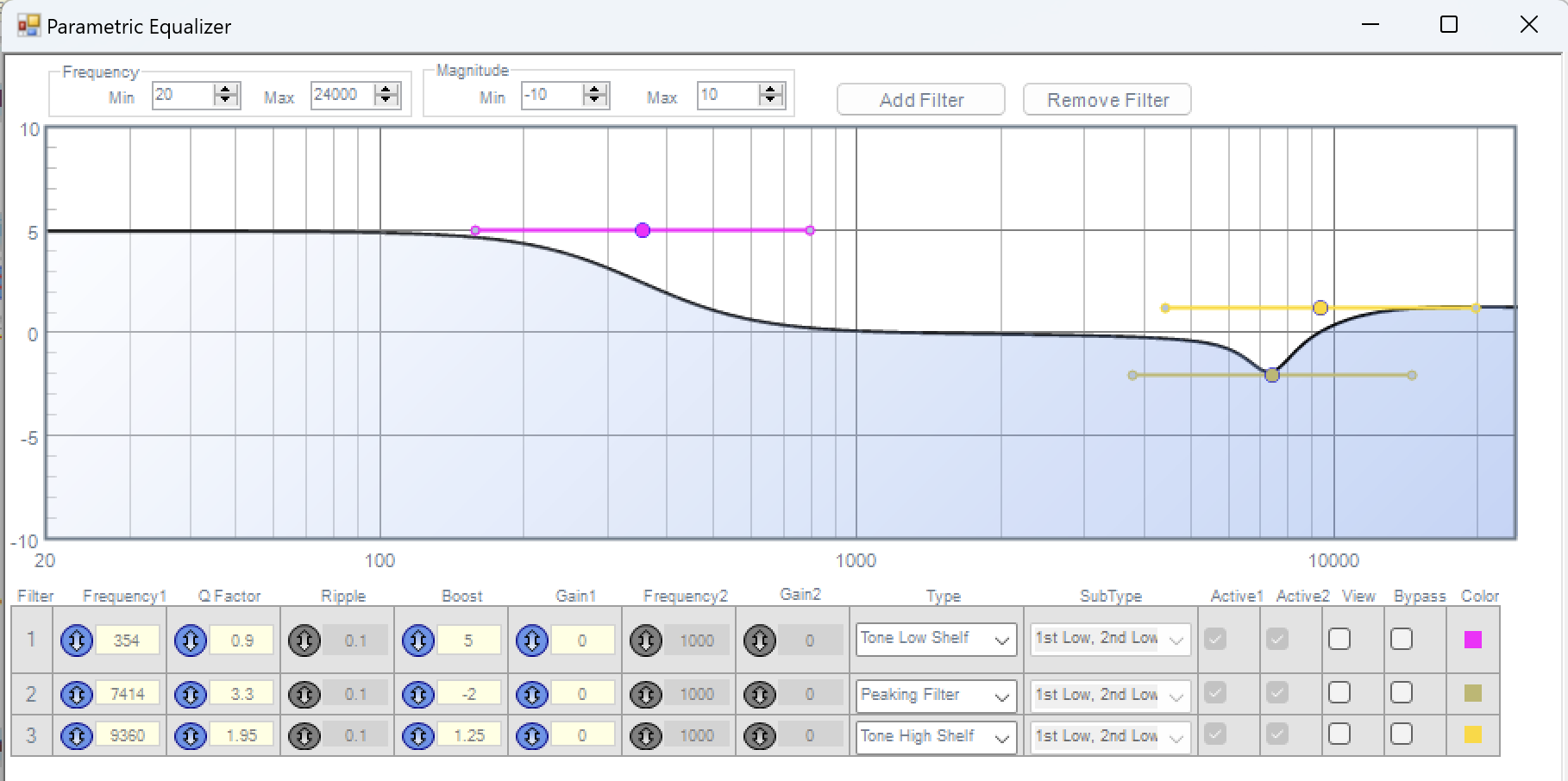
The HF EQ Filter (screenshot from SigmaStudio)
The low shelf is the important one: it props up the BMR's falling response at the bottom of its range so it meets the woofer flat at the crossover, in the same spirit as a Linkwitz transform. The peaking cut takes down a driver resonance around 7 kHz, and the small top shelf restores a little air at the very top. Your drivers will want different numbers — this table is the shape of the solution, not the solution. Measure your driver in its enclosure, then EQ flat down to your crossover point, watching excursion and power handling as you extend it.
After the EQ, a software level trim matches the HF section's sensitivity to the woofer's. Doing this digitally, on a slewed volume block, means level matching is a measurement exercise rather than a resistor-swapping one, and it can be revisited in thirty seconds any time the design changes.
Time alignment. The aligned front BMR and woofer radiate from opposite faces of the cabinet, and the HF EQ adds its own group delay. A 0.5 ms delay (24 samples at 48 kHz) on the HF path lines the two sections up at the front of the speaker, tuned by the invert-and-null method described in Step 3.
The omni/cardioid routing. After the delay, the HF signal splits into front and rear feeds through two parallel routings, and the mode switch selects between them with a mux:
- Omni: front and rear BMRs get the identical signal. Two matched drivers back to back approximate a single source radiating evenly all round.
- Cardioid: the front BMR gets the signal unchanged; the rear BMR gets a copy delayed by 1 ms (48 samples) and inverted. As covered in Step 3, the delayed anti-phase rear output cancels the front driver's radiation behind the cabinet and reinforces it in front.
The mux switches the routing as a unit, so the mode change is a single clean transition. One practical touch worth copying: each output has a mute block in line. During development these are invaluable — measuring one driver at a time (which the cardioid delay tuning requires) becomes a checkbox in SigmaStudio rather than a trip to the speaker with a screwdriver.
Setting the cardioid delay: rigorous vs quick. A note on how the 1 ms delay was arrived at, because it's a good illustration of a choice you get to make all through a project like this. The rigorous method: put a microphone behind the speaker, capture an impulse response from the front BMR alone, then the rear BMR alone (those mute blocks again), and read the required delay directly off the difference in arrival times. That measurement automatically includes diffraction, the true acoustic centres of the drivers, and any latency differences in the DSP paths — everything a tape measure approximates. What I actually did: estimated the wrap path around the cabinet with a tape measure, converted to samples, then put a microphone behind the speaker and nudged the delay up and down until the null was as deep as it would go. Both routes end at a working cardioid. The measured route gets you there faster when the geometry is complicated and tells you *why* the answer is what it is; the estimate-and-verify route needs less setup and is entirely adequate when you can hear or measure your way to the goal. Knowing when rigour pays and when it doesn't is most of what engineering judgement is.
c. Tone Controls
All three tone controls are built on the same SigmaStudio block: the *index selectable 2nd order filter*. You give it a family of filter curves — a shape, a frequency, a Q, and a range of gains — and SigmaStudio pre-computes the coefficients for every curve in the family at compile time. At runtime, an integer on the block's control input picks which curve is live, and a built-in slew smoothly interpolates between adjacent curves so the response glides rather than steps as you turn the knob. The important economics, mentioned in 8a: the curves are just stored coefficients. A 19-curve bank costs the same processing as a single fixed filter, so generous, fine-grained controls are essentially free.
Reading a pot into an index. Each control pot is wired across the DSP's auxiliary ADC inputs, which deliver a value between 0 and 1. Converting that to a curve index uses a standard SigmaStudio idiom: multiply the ADC value by the number of curves, with the multiplier constant entered in "28.0" integer format rather than the default "5.23" fractional format. The result is an integer index that sweeps 0 to 19 across the pot's rotation. A Min block against a constant of 18 then clips the top of the range, since a 19-curve bank has valid indices 0 through 18 and the multiply can just touch 19 at full rotation. If that format business sounds cryptic, it is — section 8e explains what's actually going on, and it's the single biggest source of head-scratching when modifying this design.
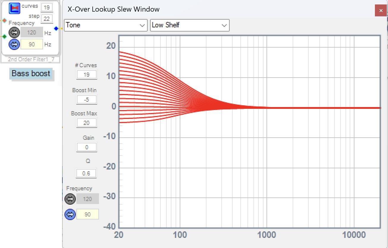
The bass control indexes 19 low-shelf curves at 90 Hz, Q 0.6, spanning −5 to +20 dB of shelf gain. A caution on reading those numbers: they're the *parameter* values of the shelf, the asymptotic gain the filter reaches well below its corner. Within the speaker's actual bandwidth the effect is smaller — at the 50 Hz limit of the system the real range is roughly −3 to +15 dB, tapering to nothing above 300 Hz. When you design your own curve family, judge it by what the curves do inside your speaker's passband, not by the numbers in the parameter boxes.
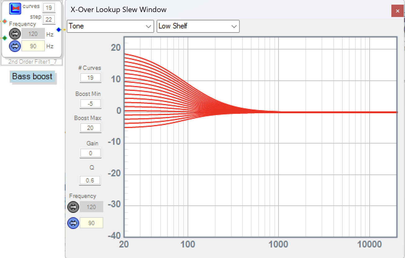
Bass Boost Filter Bank (screenshot from SigmaStudio)
The mid-bass shaping filter is the subtle one, and my favorite trick in the control layer. First, a detail about the bass bank that makes it work: the curve family is deliberately *not* symmetric around the filter's flat response. I measured the speaker in a typical room during early testing and shaped the curve profile so that **index 9 gives acoustically flat bass** — the baseline correction for the speaker and a nominal room is folded directly into the tone bank, which saves burning a separate filter stage on flattening the response before the boost. The filter's mathematical flat point and the speaker's acoustic flat point are different things, and it's the acoustic one that matters.
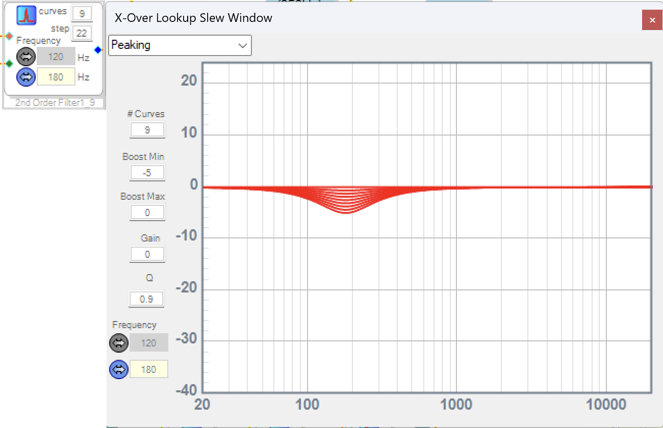
Mid-Bass Filter Bank (screenshot from SigmaStudio)
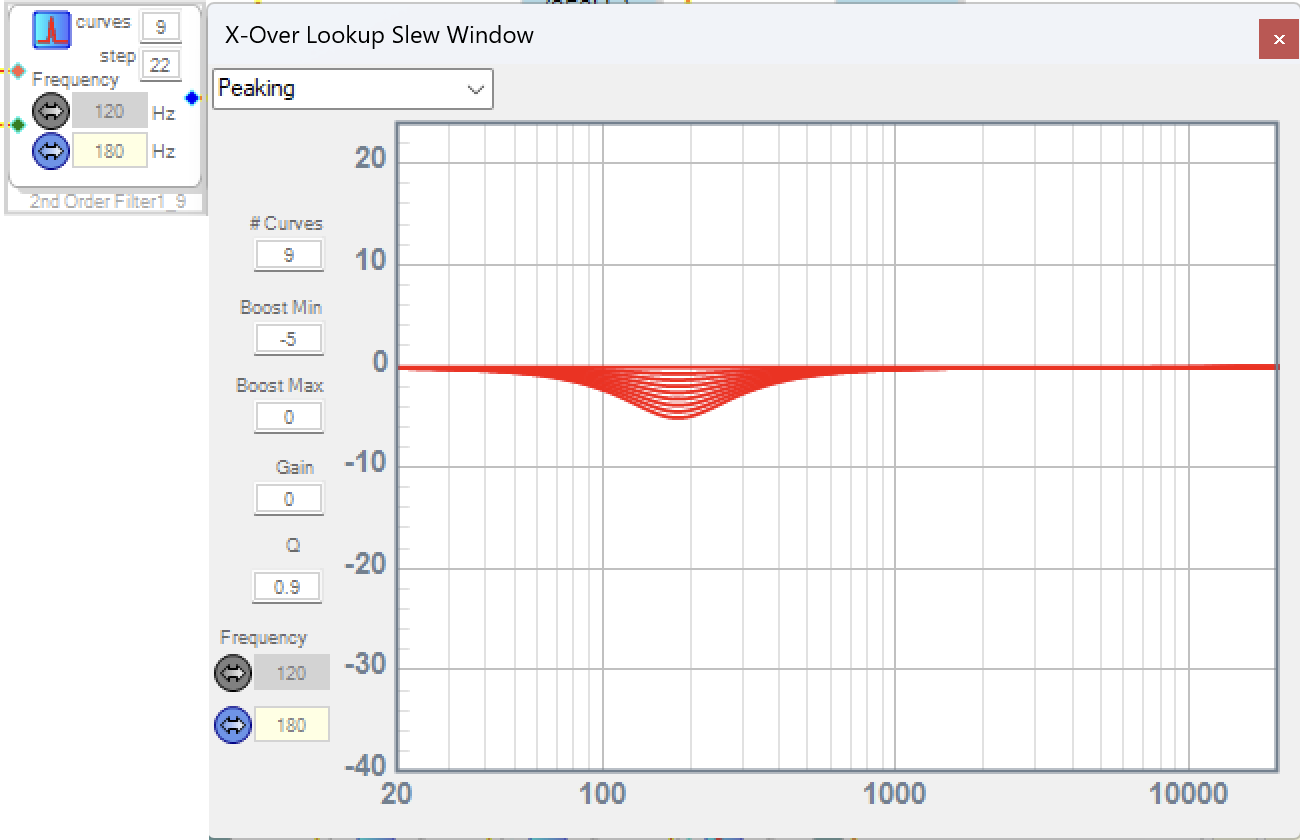
The mid-bass shaping filter is a second bank — 9 peaking curves at 180 Hz, Q 0.9, running from flat down to −5 dB — driven by the *same* pot as the bass control, with its index clipped to the 0–8 range. Those indices are exactly the below-flat half of the bass knob's travel, so the shaping filter only acts when you're cutting: turn the bass down past acoustically flat and a progressively deeper notch develops at 180 Hz alongside the deepening shelf cut. The reason it exists: voices recorded close to the microphone — podcasts especially — pick up a chesty, resonant quality when there's too much energy in the upper bass. Turning the bass knob into the cut range now doesn't just pull down the low end, it specifically cleans up that congestion. One knob, two filter banks, and the extra behavior appears exactly where you'd reach for it. No extra control needed and, per the economics above, nearly no extra DSP cost.
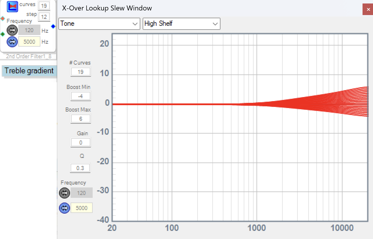
The treble control indexes 19 high-shelf curves at 5 kHz with a deliberately low Q of 0.3, spanning −4 to +6 dB. The low Q is the point: it stretches the shelf's transition region across several octaves, so instead of a step in the response you get a gentle tilt beginning around 1 kHz and developing fully by 20 kHz. Small adjustments read as "a bit brighter" or "a bit more relaxed" rather than "the treble is on or off," which is what you want when the goal is matching the speaker to the liveliness of a room. The asymmetric range (+6/−4) isn't scientific — it just centers the knob on what sounded right to me in early listening, with the range I found myself actually using on either side of it.
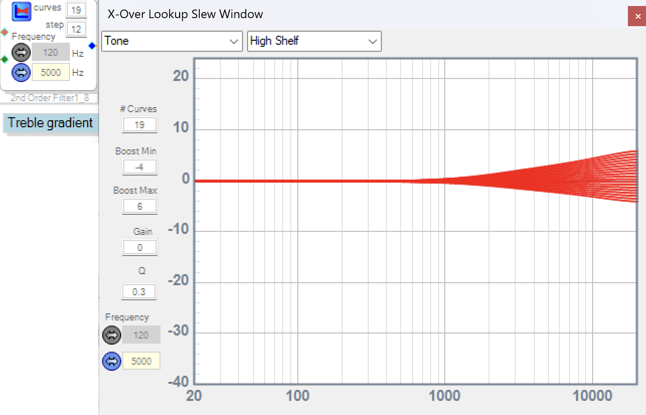
Treble Control Filter Bank (screenshot from SigmaStudio)
The mode switch demonstrates one more control-layer trick. The omni/cardioid selector is electrically just another pot on an ADC input, but its value feeds an ABCD comparator block with a threshold at 0.5, which outputs a clean 0 or 1 — turning a continuous control into a two-position switch in software. That integer drives the mux that swaps the HF routing between the omni and cardioid paths. The same pattern extends to multi-position rotary switches built from resistor ladders: a bank of comparators at the right thresholds converts whatever awkward voltages your resistor values produce into clean switch positions. If your build wants a three- or four-position mode selector, this is how to do it without adding anything more exotic than resistors to the hardware.
d. The Dynamic Bass Limiter
This is the part of the design I'd most encourage you to study, because nothing like it exists as a ready-made block, and the idea transfers to any DSP speaker with more EQ boost on offer than power to back it.
The problem, restated. The bass control offers up to 15 dB of real boost. At low volume that's the difference between thin and satisfying. At high volume it's a demand for about thirty times more amplifier power than running flat — power a 60 W battery amp doesn't have. Somewhere between those extremes the boost has to give way, and the question is what does the giving.
The idea. The bass knob sets an index into the filter bank: 0 to 18, more index, more bass. The limiter computes a second number in exactly the same units — *the maximum index the system can currently afford* — and a Min block passes whichever of the two is smaller to the filter. That's the whole mechanism. When the music is quiet, the affordable index is high and the knob wins; the user has full authority. As the level rises, the affordable index descends, and wherever it crosses below the knob position, the limiter takes over — smoothly, because the filter bank slews between curves. There's no mode change, no bypass switching, nothing for the user to notice except that the speaker keeps sounding clean.
I find this genuinely elegant: the limiter doesn't process audio at all. It just argues with a knob, and the Min block moderates the debate.
Watching the right signal. The sidechain taps the signal right after the volume control and low-pass filters it at 300 Hz before level detection. The reasoning: this limiter's only weapon is reducing bass boost, so it should react to bass-band demand. If a bright, cymbal-heavy passage triggered it, the bass would duck for no audible benefit. The tap point matters too — it's *before* the bass boost filter, so the detector sees the untreated signal level, which is what the threshold is calibrated against.
Level detection. An Envelope Peak block tracks the filtered signal with a 100 ms hold and a decay of 50. The hold stops the boost from starting to creep back during brief gaps between beats; the decay sets how quickly bass returns after a loud passage ends. These two parameters are where the limiter's *feel* lives, and Step 9 covers tuning them. Worth knowing: SigmaStudio has two envelope block families, and they output different things — see the gotchas in 8e before you substitute one for the other.
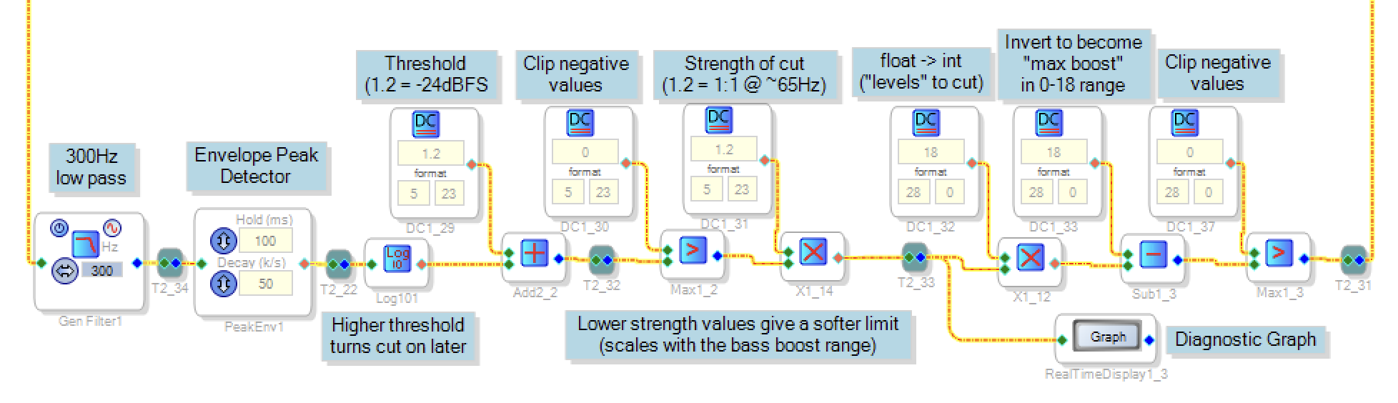
The arithmetic: thinking in dB. Both the amplifier's headroom and the filter bank's curve spacing are naturally described in dB, so the control law is simplest there: *for every dB the signal rises above a threshold, take away about a dB of boost.* The chain implements exactly that sentence:
- Log10 block converts the envelope's linear amplitude to log domain. (True dB values like −20 would overflow the DSP's native ±16 number format — one of several format traps covered in 8e — so the chain works in raw log10 units, where each 0.05 is a dB.)
- Add a threshold constant (+1.2 here). The output crosses zero when the signal is at −24 dBFS: below threshold it's negative, above it grows with level.
- Max against 0 clips the below-threshold region — quiet signals produce zero cut.
- Multiply by strength factor (1.2) sets how much bass is cut back with increasing input volume. Is frequency dependent because the boost is frequency dependent. 1.2 is approximately a 1:1 cut with increasing volume at 65Hz, higher frequencies have a soft cut, (frequencies below 65Hz actually get a slight negative gain).
- Multiply by 18 (inc. float to int conversion), map from 0-1 to 0-18 to match the number of curves on the bass boost.
- Subtract from 18 flips "steps to cut" into "maximum allowed boost index" on the bass knob.
- Max with 0 to clip negative values
- Min block (on main diagram) against the knob position
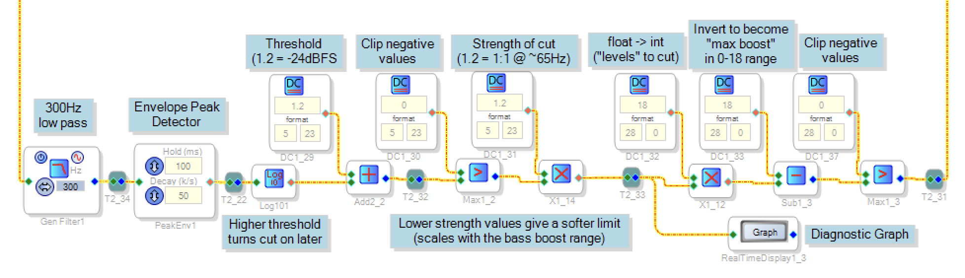
Dynamic Limiter Signal Chain (screenshot from SigmaStudio)
A RealTimeDisplay block on the computed limit gives a live diagnostic graph while tuning — you can watch the limit dive when the music gets loud and glide back up after, which makes calibration far less abstract.
Calibrating it. Two numbers do all the work, and they're tuned differently:
- The threshold (onset) is best set empirically: turn the boost up to maximum, play bass-heavy material with the limiter's cap disabled, turn the volume up to a level where distortion or port chuffing becomes clearly audible, then gradually increase the threshold parameter until the distortion is controlled. Ears are the right tool here because the failure modes (amp clipping, port noise, driver stress) are audible events.
- The strength is best set analytically, and the 1 dB-per-dB argument does it for you: every dB of signal above threshold consumes a dB of headroom, so a dB of boost must be surrendered to compensate. Work out what one curve step is worth in dB in your filter bank at low end of the frequency range, and the multiplier constant follows. You can confirm the behavior using a sine tone generator and the diagnostic graph. As you turn the volume up and the limiter comes in
Tuning the feel: hold and decay. With onset and slope fixed, the envelope detector's hold and decay settings determine the time response — and this is where most of its perceived quality lives, because cutting bass during loud passages is well masked, while bass swelling back in afterwards is where audible pumping hides. The hold (100 ms here) keeps the envelope pinned through brief gaps between beats, so the boost doesn't flutter back mid-phrase. The decay sets how quickly the boost returns once a loud passage genuinely ends. The values I've used are a reasonable default across a range of content.
e. SigmaStudio Gotchas (Lessons Learned)
SigmaStudio is powerful and free, but parts of it are thinly documented, and several behaviors cost me real debugging time. This section is the list I wish I'd had at the start. It's specific to the ADAU1701 (the DSP in the KABD-430); other SigmaDSP parts differ in detail.
Two number formats, and blocks that disagree about which one they speak.The ADAU1701 stores every value as a 28-bit word, but there are two data types. Audio and most control signals use "5.23" floating point with a range limited to roughly ±16, where full-scale audio is 1.0. But some blocks — critically, the index input on the index-selectable filter and mux blocks — read their input as a "28.0" integer. Feed a 5.23 float value of 1.0 into an index input and the block sees the raw bit pattern: 8,388,608, pegging the input to the top curve.
The rule that makes everything work: anything feeding an index input must arrive as a 28.0 integer, and you control this through the format boxes on DC constant blocks. Two rules follow:
- Pot to index: multiply the ADC signal (5.23, 0 to 1) by a constant equal to the number of curves, with the constant's format set to 28.0. The multiply's raw result is then exactly the integer index 0–N. This looks like a magic incantation the first time you see it; it's really just how the fixed-point multiply's bit-shift lands when one operand is an integer.
- Logic to index: comparator blocks output 1.0 in 5.23 by default — which is that huge raw integer again. Set their output constants to 28.0 format and comparator outputs become clean 0s and 1s you can sum, subtract, and feed to muxes. The limiter's arithmetic chain switches from 5.23 to 28.0 at its multiply step for exactly this reason.
You can't put real dB values in the signal path. Related to the above: 5.23 covers ±16, so a value like −20 (dBFS) simply doesn't fit. Any arithmetic you'd naturally do in dB has to be rescaled — the limiter works in raw log10 units (1/20th of dB) and converts to integer curve steps at the last moment. If a chain that should work is misbehaving, check whether an intermediate value has quietly exceeded ±16.
The two envelope detector families output different quantities. The "Envelope Peak" block outputs what you'd expect: the signal's peak amplitude. The "Signal Envelope" block, despite its tooltip mentioning RMS, outputs the *mean square* — amplitude squared, no square root. Feed that into log-domain arithmetic and everything is silently off by a factor of two (log of a square doubles the log). If you want true RMS, follow the Signal Envelope with an explicit square-root block. If you swap one family for the other, re-derive your constants.
Envelope decay is linear, not exponential. The envelope detectors release at a fixed *amplitude* per second, not a fixed dB per second. On a dB scale that means recovery is slow near the top and accelerates as it falls. For this design it's fine, but if you're expecting studio-compressor release behavior, it isn't that.
Getting the files!
Instructables doesn't seem to accept the SigmaStudio Projects as attachments, so I've put them on Thingiverse here, along with my other DSP projects:
Tuning It in Your Room
Everything so far has been about building the adjustability in. This step is about actually using it — and it takes only seconds
The mode switch first. The rule of thumb is simple: within a couple of feet of a wall, cardioid; anywhere open — mid-room, outdoors, on a kitchen island — omni. The difference is easy to hear if you A/B it in place: against a wall in omni mode the sound is thicker and less distinct, especially on voices; flip to cardioid and the midrange firms up as the rear-wall bounce disappears. If you can't hear a difference in a given spot, the placement probably doesn't care, and either setting is fine.
Then the bass shelf. Set it by ear based on current situation, and personal preference. Get a feel for how the response of the speaker naturally chan get as you put it in different locations. Situated outdoors or on an open table will benefit from a generous helping of boost, a bookshelf against a wall requires relatively little little, and if you place it right in a corner you may want none or a touch of cut.
The treble gradient last. This one is taste plus room. Lively rooms — tile, glass, bare walls — bounce treble energy around and usually want the tilt eased back a step or two; soft furnished rooms swallow it and want a step or two up. Just tweak according to your preference.
Optimizing for podcasts and the spoken word. Remember from the DSP section, that the lower half of the bass knob does double duty: below the acoustically-flat point, the mid-bass notch develops alongside the shelf cut. If you are finding voices sound overly chesty or boxy, try turning the bass level down below the midpoint, you should find they sound more natural.