Boat Prototype
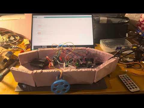
This project is a prototype of a fully functional Arduino-powered boat, designed for stability, wireless control, and potential expansion. The base of the boat is constructed using styrofoam (at least one inch thick) to ensure buoyancy and balance. At the core of the system is an Arduino board, which controls 2 stepper motors with IR sensor.
Supplies
- Styrofoam (at least an inch thick)
- Arduino (Any kind will work, but prefer Arduino Wifi Uno R4 Model for future development)
- 2 28BYJ-48 4-Phase Stepper Motor
- 2 ULN2003 driver board
- 1 Remote Control
- 1 IR sensor
- Breadboard and wire (the smaller the breadboard is, the better)
- 3D-printed paddles can be attached to the stepper motors
- 2 power modules (9V battery) for Arduino and Motor
Make Boat Structure
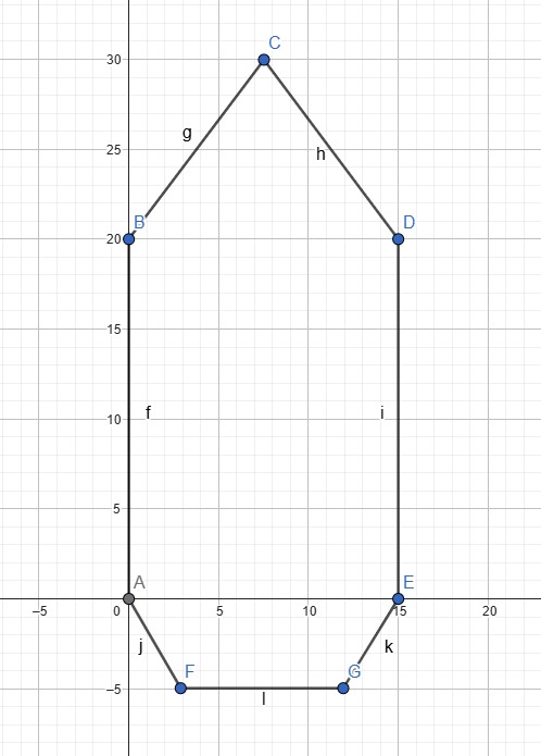
- Prepare a 30cm x 30cm Styrofoam, and at least 2.5cm (or 1 inch thick)
- Cut the boat like in the shape in the diagram (1 unit = 1 cm)
- Cut the wall for the boat to line up with the bottom of the boat in the diagram (7 cm tall)
- Stick wall and bottom of boat with type
Arduino Motor Wiring

- Carefully place both the Arduino board and the power module inside the boat in a secure and dry area. Make sure they are positioned in such a way that they remain stable during movement and are protected from water exposure.
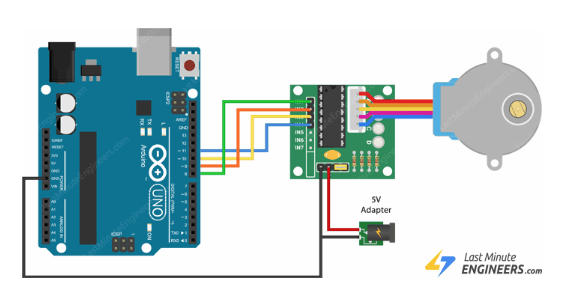
- Connect the Arduino to the motor following the wiring diagram shown in the provided image. Ensure that the motor driver or control circuit is correctly wired to the Arduino’s output pins, and double-check all connections to avoid loose or incorrect wiring that might affect performance.
- Firmly attach the motor to the side of the boat using double-sided tape or another strong adhesive method. Make sure the motor is aligned properly to ensure efficient propulsion. Test the placement by gently shaking the boat — the motor should stay firmly in place and not wobble. You may reinforce the mount with waterproof tape or a lightweight bracket if needed.
Arduino IR Sensor Wiring
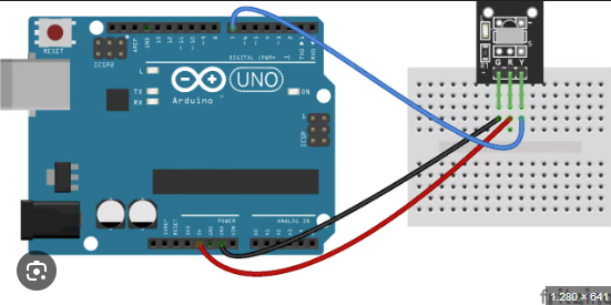
- Connect the IR sensor according to the wiring shown in the reference image. Carefully match each wire from the IR sensor to the appropriate pins on the Arduino. Typically, this will include connecting the VCC (power) pin to the 5V output on the Arduino, the GND (ground) pin to the GND on the Arduino, and the OUT (signal) pin to one of the digital input pins. Double-check the orientation and wire colors to ensure proper alignment with the reference image.
- Once you have completed the wiring, move on to setting up the code for the IR sensor. Open the Arduino IDE on your computer, create a new sketch, and begin by defining the pin connected to the IR sensor’s output. Write a simple code block to read the sensor's digital input and respond accordingly—for example, turning on an LED or printing a message to the Serial Monitor when the sensor detects an object. Upload the code to your Arduino and test the sensor to make sure it is functioning as expected.
Upload and Run Code for Arudino
#include <Stepper.h>
#include <IRremote.h>
#define IR_RECEIVE_PIN 12
#define IR_BUTTON_1 12
#define IR_BUTTON_2 24
#define IR_BUTTON_3 94
#define IR_BUTTON_PLAY_PAUSE 64
const int stepsPerRevolution = 2038;
int motorSpeed = 0;
bool isMotorRunning = true; // Track motor state
Stepper myLeftStepper(stepsPerRevolution, 8, 10, 9, 11);
Stepper myRightStepper(stepsPerRevolution, 7, 5, 6, 4);
void setup() {
Serial.begin(9600);
IrReceiver.begin(IR_RECEIVE_PIN);
}
void loop() {
speedControl();
if (isMotorRunning && motorSpeed > 0) {
// Instead of blocking, move the motor in small steps & check for input
for (int i = 0; i < stepsPerRevolution; i += 1) {
myLeftStepper.setSpeed(motorSpeed);
myRightStepper.setSpeed(motorSpeed);
myLeftStepper.step(-1);
myRightStepper.step(1); // Move 10 steps at a time
speedControl(); // Check for IR input after small movement
}
}
}
void speedControl() {
if (IrReceiver.decode()) {
int command = IrReceiver.decodedIRData.command;
IrReceiver.resume();
switch (command) {
case IR_BUTTON_1:
Serial.println("Pressed on button 1 - Motor ON");
if (motorSpeed < 16){
motorSpeed += 1;
}
break;
case IR_BUTTON_2:
Serial.println("Pressed on button 2 - Motor OFF");
if (motorSpeed > 1){
motorSpeed -= 1;
}
break;
case IR_BUTTON_3:
Serial.println("Pressed on button 3 - Reserved action");
isMotorRunning = !isMotorRunning;
break;
default:
Serial.println("Button not recognized");
}
}
}
Code Explaination
This Arduino sketch is designed to control a small boat using two stepper motors and an infrared (IR) remote. It begins by including two key libraries: Stepper.h for controlling the stepper motors, and IRremote.h for receiving and decoding signals from the IR remote control. The IR receiver is connected to pin 12 and listens for specific button commands defined as constants. These include IR_BUTTON_1, IR_BUTTON_2, and IR_BUTTON_3, which are used to control speed and power. While there's a constant for the play/pause button (IR_BUTTON_PLAY_PAUSE), it's not used in this version of the code.
Two Stepper objects are created to represent the left and right motors, each configured with 2038 steps per revolution. The pins connected to each stepper motor are also defined—pins 8 to 11 for the left motor and pins 4 to 7 for the right. In the setup() function, the code initializes serial communication at 9600 baud for debugging purposes and begins listening for IR signals using IrReceiver.begin().
The core of the functionality happens in the loop() function. If the motors are running (isMotorRunning is true) and the speed is greater than 0, both motors will move in small steps—specifically one step at a time in opposite directions (left motor steps backwards, right motor steps forwards) to simulate forward movement. After each small movement, the speedControl() function is called to check for any new IR input, allowing for real-time adjustments without blocking the program.
The speedControl() function listens for IR signals and adjusts the motor behavior based on the button pressed. If button 1 is pressed, the speed increases by 1, up to a maximum cap (not explicitly defined but limited by common sense). If button 2 is pressed, the speed decreases by 1, down to a minimum of 1. Pressing button 3 toggles the motor state—pausing or resuming motion. Any other button press will trigger a debug message, stating that the button is not recognized. This structure ensures that the boat remains responsive to the user's input at all times.