Bowden Tube Transmission

Have you ever heard of Bowden tubes ? It is an invention attributed to Frank Bowden over 100 years ago and the most visible application of this invention is in display in our everyday life as bicycles brake cable routing or 3D printer filament guide. Simply explained, the Bowden tube use a tube in which a an in-extensible cable can be pushed and/or pulled relative to the outer tube. This works if the outer tube is stationary relative to the motion of the inner cable.
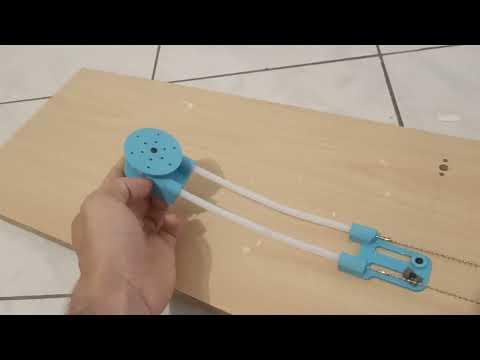
In this Instructable, I want to explore using a Bowden tube to do a little more than « just » a push pull motion, I want to use this invention to transmit rotation motion through the use of 2 Bowden tube ran in parallel. This presents several advantages and challenges that I will describe in the coming parts and illustrate with a proof of concept that is not an actual useful project but simply a demonstrator of what this system can do.
Supplies
3D printer
3mm steel beads chains
28BYJ-48 stepper motor (The system can be adapted for any motor you already have)
Stepper motor controller (I am using an Arduino Uno with ULN2003 motor driver)
Overview
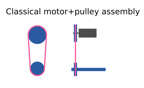
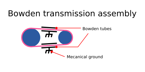
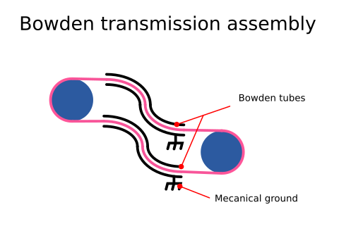
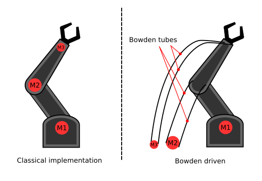

This concept uses 2 low friction Bowden tubes (PTFE) allowing to route a belt in any shapes, contrary to classical motors+belt assemblies, this solution provides great flexibility (pun intended) on the position of the motor relative to the end effector, indeed in a classical belt and pulley implementation, the axis of rotation of the motor is usually parallel to the axis of rotation of the end effector. In addition, if an end effector has multiple degrees of freedom (think robot hands, robot dog legs, etc.), the motors are usually mounted on one of the moving part (for example, in a humanoid robot the wrist moves with motors are usually mounted on the forearm assembly which in turn is moved with the elbow assembly etc) increasing the weight of the moving part of the mechanism. Using Bowden tubes, you could have all motors static and Bowden tubes to the different joint. This makes for a lighter robot or rather for a lighter moving mechanical assembly (all the motor are static in this example).
Belt Choice
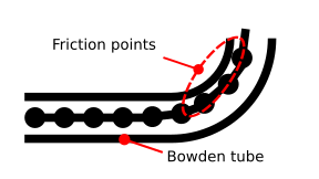
This system is far from perfect and one of the main challenge is the friction between the Bowden tube and the belt making the choice of the belt of paramount importance. In fact, the choice of PTFE tubing was made because beyond its availability, it has so low friction with most other material that it is dubbed a « self lubricating » material. Another aspect to consider when choosing the belt is that it has to present an axis of symetry along the pulling/pushing motion because the twist and turns that the Bowden tube can take. Finally the belt has to be relatively cheap to buy.
My first thought was to get a in-extensible wire but it is actually not that easy to find a small diameter in-extensible wire. In addition I like the idea of chains better than wires as you can provide much more torque with chains than with wires
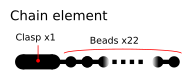
Using 3mm steel beads chain meets all of these criteria, they are cheap, the round beads make them twist able and turn able and steel beads have very low friction with PTFE tubing. An added bonus is that the chain can be lengthened and shortened at will. The only downside is that although I will be able to get more torque through the system with a bead chain than using a wire, the bead chain is more prone to skipping than regular chain or belt.
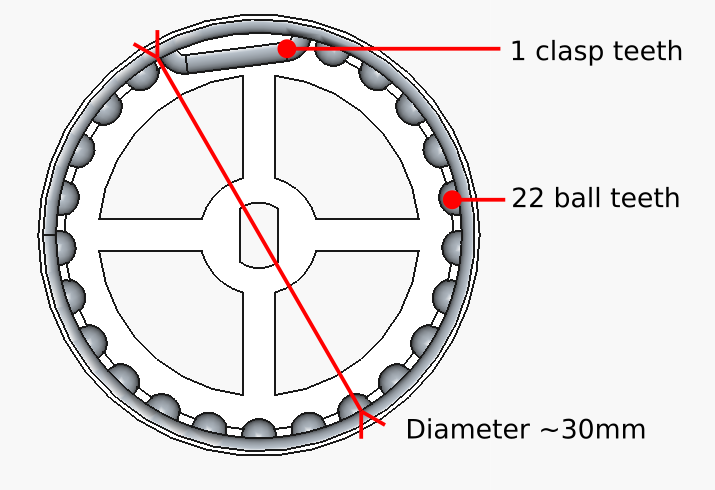
On challenge of using those cheap steel beads chains is that they are quite short and the clasp makes the beads chain not ideal to be belt driven. In order to accommodate for this, I chose a number of beads in between 2 clasps I call this my « chain element ». As long as I account for the clasp in the wheel design it works fine. It should be noted that if the belt skips, then I will have trouble driving the belt, it is one of the main challenge, the belt has to be « in phase » with the wheels.

As previously explained, the motor are placed away from the end effector making for a more flexible mechanical system . By that I mean that the motor can now be placed wherever there is still space (in a robot for example)
The "Continously Distributed Pulley"
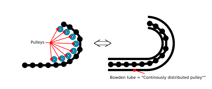
In a classical belt or cable system, there are usually tensioning pulleys in order to tighten the belt or cable. In my implementation, I can coarsely tune the length of the total belt by choosing the number of chain element (think of it as a coarse digital tuning) and then I adjust the tension by moving the tensionner relative to the motor (fine analog tuning). When tensionning the chain is pressed on the side of the PTFE Bowden tube showing once again that the choice of material for the belt and for the Bowden tube is very important. One interesting thing to note is that the Bowden tube works as if there was a lot of tiny pulley on the side guiding the belt. I call this the « Continuously distributed pulley effect »
Conclusion
Although having limited torque capability, this system presents interesting features, including flexibility, reduced cost but also simplicity while reusing a concept at least 100 years old which is quite interesting. The application for this system are quite numerous although it does comes with challenges.