Build Your Own 8-Zone Smart Irrigation Controller
by jesusmartinezmateo in Living > Gardening
74 Views, 1 Favorites, 0 Comments
Build Your Own 8-Zone Smart Irrigation Controller
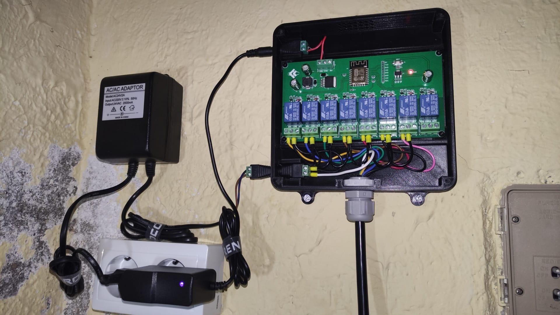
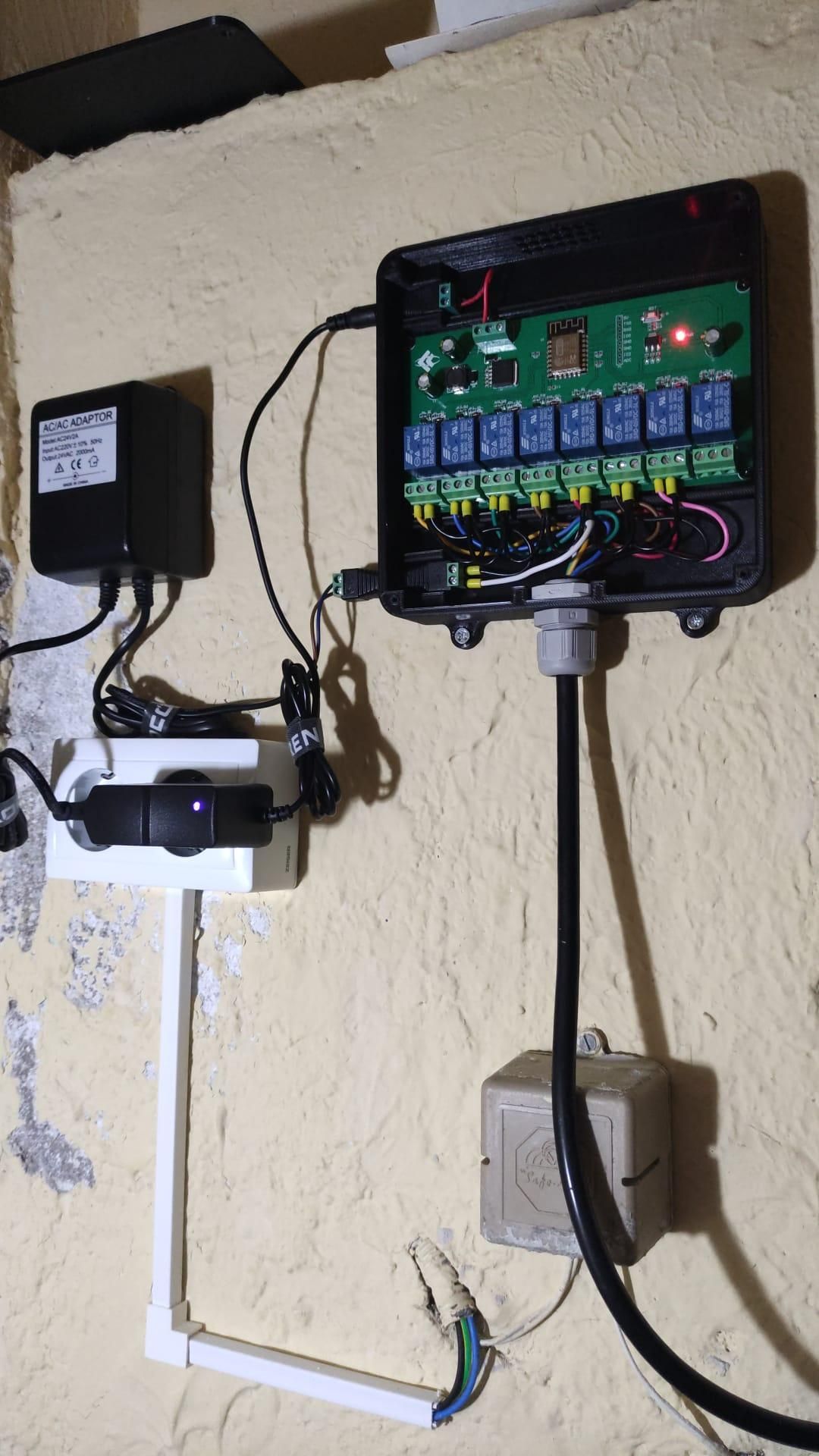
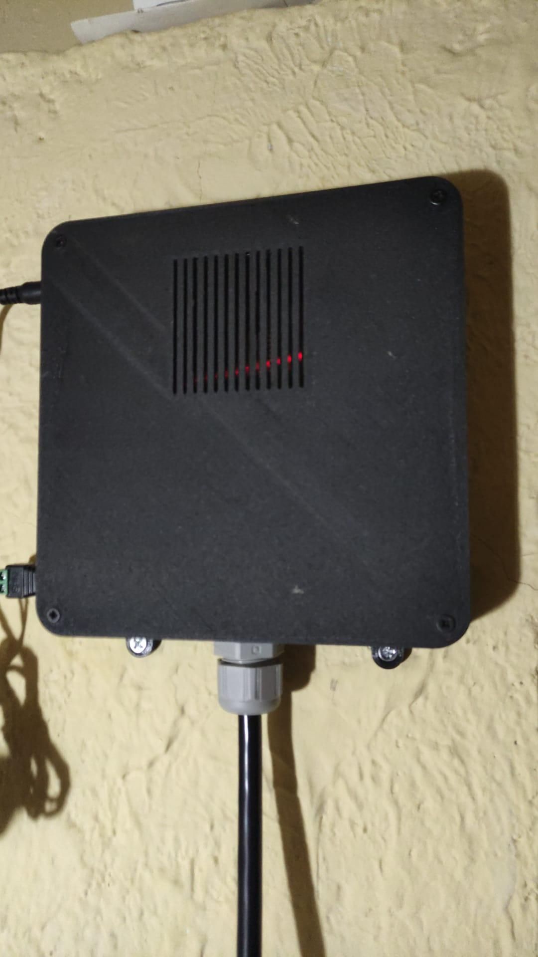
For years, I had been wanting to replace my old irrigation controller. Although it worked fine, every power outage erased its programming and stopped the watering schedules. In addition, whenever I wanted to change the watering time or the duration of any zone, I had to manually reprogram the entire system.
For these reasons, I decided to build my own smart irrigation controller.
The result is a WiFi-enabled irrigation controller that can manage up to eight zones independently and can be controlled from a web browser or integrated into Home Assistant. This project also includes a custom 3D-printed enclosure designed specifically for the controller.
Supplies
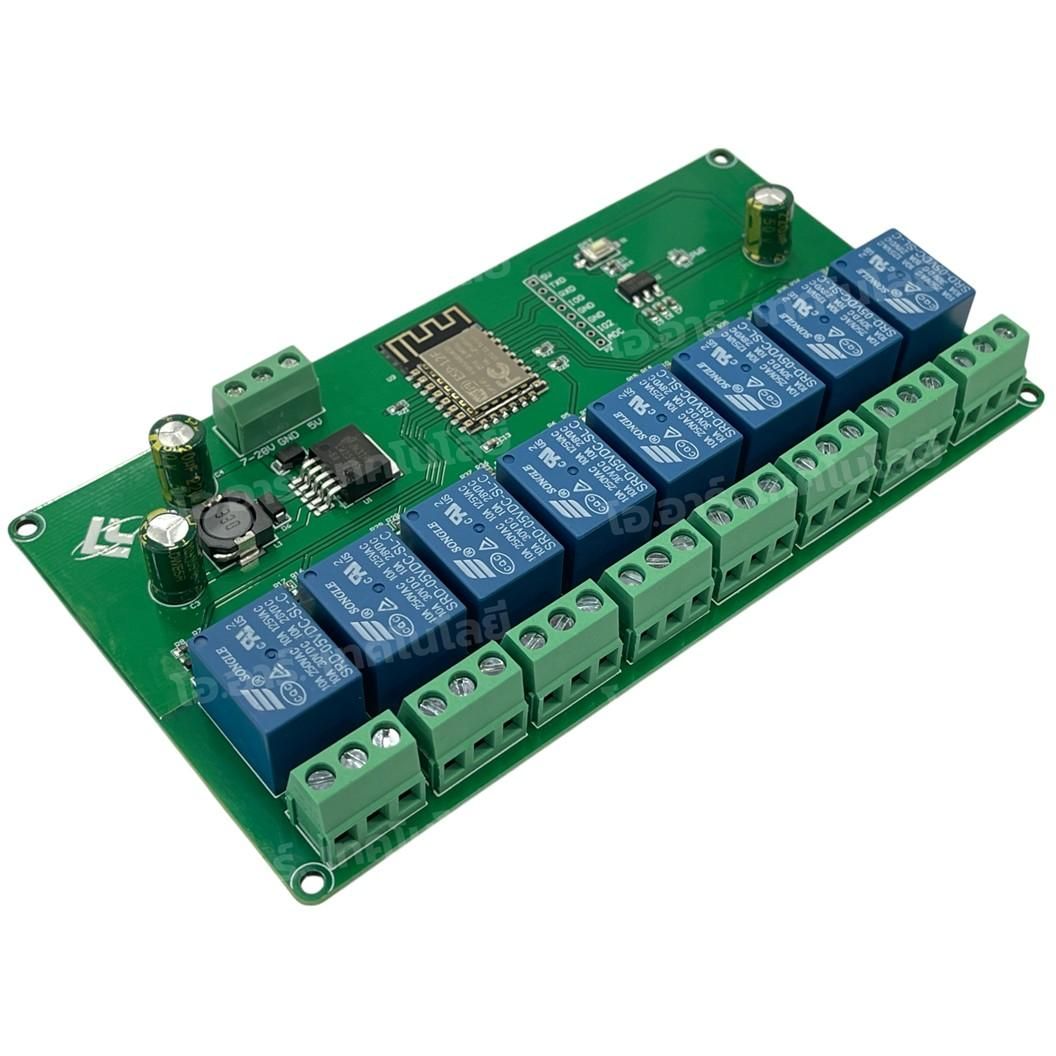
- ESP12 Relay X8 board (based on the ESP8266 WiFi microcontroller)
- 2.1 mm x 2.5 mm DC Barrel Jack Connectors
- M20 IP68 Cable Gland Kit (gland, seal and locknut)
- 9-core irrigation cable (8 zones + common wire)
Approximate cost: 20-30 euros (excluding the valves and transformer).
Notes (my Build)
- The design only requires the enclosure to include two female DC barrel jacks. However, my 24V AC transformer came with bare wires, so I also used a male DC barrel plug to connect it to the enclosure.
- Since my installation only uses 7 irrigation zones, I used an 8-core irrigation cable instead of a 9-core one. The cable includes seven 0.5 mm^2 cores for the irrigation zones and one 1.0 mm^2 core used as the common wire for all valves.
Understanding the System
Before starting the assembly, it's worth understanding the overall architecture of the smart irrigation controller and how the different components work together.
The system is designed to support up to eight independent irrigation zones using a single controller. Each relay controls one irrigation valve, making it possible to manage sprinkler zones, drip irrigation zones, or any combination of both.
The controller itself is powered by a DC power supply, while the irrigation valves are powered by a separate external power source. The controller electronics is separated from the valve power circuit. This makes the design very flexible, since it can be used with standard 9V DC or 24V AC irrigation valves, depending on the requirements of your installation.
At the heart of the project is an ESP12F Relay X8 board running Tasmota firmware. I chose Tasmota because it runs locally, ant does not depend on external cloud services. Tasmota provides a web-based interface for configuration and control, supports MQTT, and can be integrated with home automation platforms such as Home Assistant.
To make the installation more robust and easier to maintain, all electronics are installed inside a custom 3D-printed enclosure specifically designed for the ESP12F Relay X8 board.
Main Features
- Control of up to 8 independent irrigation zones
- Suitable for sprinkler and drip irrigation systems
- Compatible with both 9V DC and 24V AC valves
- WiFi connectivity for remote access and automation
- Web-based configuration and control
- MQTT support
- Home Assistant integration
- Custom 3D-printed enclosure
3D Print the Case
.png)
.png)
One of my goals was to create a neat and reliable installation, so I designed a custom enclosure specifically for the ESP12F Relay X8 board. The enclosure securely holds the controller, provides enough room for wiring, and includes openings for the cable glands used to route the irrigation zone cables and power connections.
You can download the enclosure from MakerWorld: ESP12F Relay X8 Case
Wiring the Controller
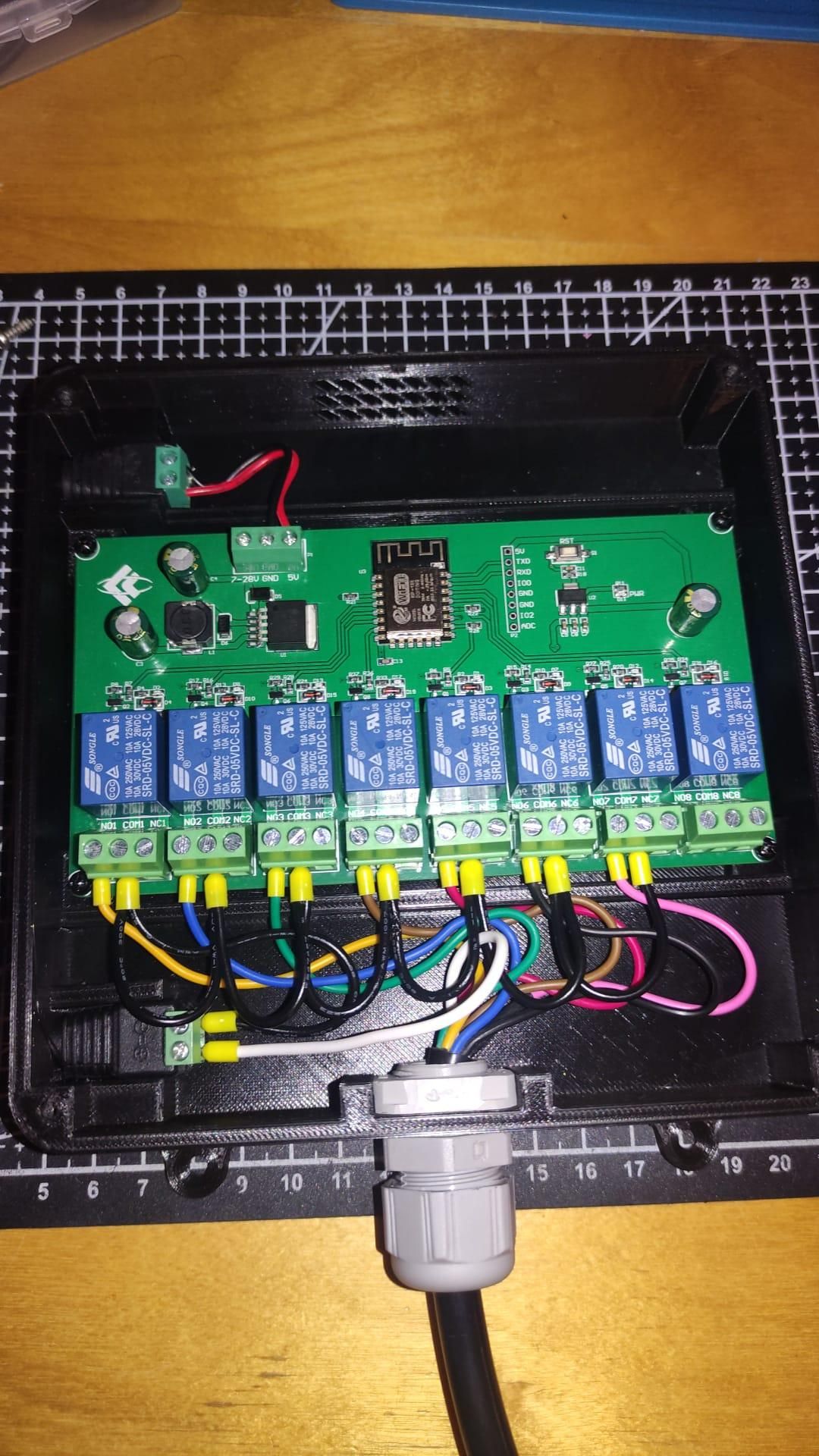
With the board installed inside the case, the next step is to complete all electrical connections.
A DC barrel jack is installed at the top of the enclosure to power the ESP12F Relay X8 board. The controller can be powered with either 5V DC or any DC voltage in the 7-28V range. To accommodate both options, the board features a three-terminal power input: a common GND terminal in the center, a 5V DC input terminal on the right, and a 7-28V DC input terminal on the left. The barrel jack should be wired to the board's power terminal according to the supply voltage used.
A second barrel jack is installed at the bottom of the enclosure to power the irrigation valves. This connector is compatible with either a 24V AC transformer or a 9V DC power supply, depending on the type of valves in your irrigation system.
As shown in the photo, one wire from the valve power supply is connected to all relay COM terminals, that is, distributed to all relay COM terminals using jumper wires. Each relay NO terminal is connected to a different irrigation zone, while the common return wire from all valves is connected directly to the other output terminal of the power supply. When a relay is activated, it completes the circuit and powers the corresponding irrigation valve, starting irrigation in that zone.
Note: For DC systems, the relay COM terminals are typically connected to the positive (+) supply terminal, while the common return wire is connected to the negative (-) terminal. For AC systems, polarity does not apply.
Configuring Tasmota
Installing Tasmota is quite straightforward thanks to the official documentation and the online installer. Once Tasmota is installed and connected to your WiFi network, open the device web interface and apply the following configuration: Go to (Main Menu) Configuration → Configure Other. Under Template, paste the following:
Make sure the Activate checkbox is enabled and click Save. The device will restart automatically. In the same menu, you can also rename the relays according to your irrigation zones to make them easier to identify.
After the reboot, Tasmota will recognize all eight relays and display them on the main page, allowing each irrigation zone to be controlled independently.
Allow Only One Irrigation Zone at a Time (Optional)
To prevent multiple valves from opening simultaneously, enable relay interlocking. Open the (Main Menu) Console and run the following commands:
With interlock enabled, turning on any irrigation zone automatically turns off the previously active zone.
This configuration is optional but recommended for irrigation systems, as opening multiple valves simultaneously may reduce water pressure, resulting in poor sprinkler performance or uneven watering. It also helps avoid overloading the valve power supply transformer.
Configure Time and Location
Before creating any irrigation schedules, you should configure the device time and time zone. Tasmota provides detailed information about time zone configuration. But if you plan to use sunrise or sunset as schedule triggers, configuring the time zone is not enough. Tasmota also needs your latitude and longitude to calculate these times correctly.
For example, in my case (Madrid, Spain), I used the following Console commands to configure the device latitude, longitude, time zone, and automatic switching between winter and summer time:
Creating Irrigation Schedules (Option A)
Tasmota allows irrigation schedules to be configured directly from the web interface through (Main Menu) Configuration → Timer, where up to 16 different timers can be defined. This is a simple option if you only need to turn individual zones on and off at specific times.
However, Tasmota also provides a more flexible approach using Rules. With rules, multiple relays can be activated sequentially, allowing a complete irrigation cycle to run automatically from one zone to the next, each with its own watering duration.
In my case, I use:
- Zone 1 (drip irrigation): 15 minutes
- Zones 2 to 7 (sprinklers): 5 minutes each
- Zone 8: unused
The irrigation cycle runs:
- 2 hours after sunrise in the morning
- At sunset in the evening
To achieve this, open the (Main Menu) Console and create the required timers and rules. The timers will start the irrigation cycle, while the rule will activate each zone one after another for the required duration.
Morning Irrigation
Create a first timer to start an irrigation sequence two hours after sunrise:
Create a rule that starts a sequential watering cycle when Timer 1 is triggered:
⚠️ Warning: The rule relies on relay interlocking (see configuration above), so only one irrigation zone can remain active at a time.
In Tasmota, Delay values are expressed in tenths of a second. Therefore, Delay 9000 corresponds to 15 minutes and Delay 3000 corresponds to 5 minutes.
Enable the rule:
Evening Irrigation
Create a second timer to start the same sequence at sunset:
Then create a second rule to activate each zone sequentially:
Enable the rule:
This timer triggers the same sequence, so both the morning and evening irrigation cycles follow exactly the same order and durations.
Creating Irrigation Schedules (Option B)
Option B is an alternative approach. If you used Option A, you do not need to complete this step.
Morning Irrigation
Create a first timer to start an irrigation sequence two hours after sunrise:
Create a rule that starts a sequential watering cycle when Timer 1 is triggered:
Note: The rule is shown on multiple lines for readability. When entering it through the Tasmota console, it must be provided as a single continuous command.
TimedPower values are specified in milliseconds.
The rule activates each irrigation zone one after another, ensuring that only one valve is open at a time. Each zone remains active for its configured duration before control is passed to the next zone in the sequence.
Enable the rule:
Evening Irrigation
Create a second timer to start another irrigation sequence at sunset:
Create a second rule that starts a sequential watering cycle when Timer 2 is triggered:
This timer triggers the same sequence, so both the morning and evening irrigation cycles follow exactly the same order and durations.
Enable the rule:
⚠️ Warning: The rules above are not triggered only by Timer 1 or 2. Because each zone is chained to the next through PowerX#state=0 events, manually activating any irrigation zone may also start the remainder of the sequence automatically once that zone turns off. Depending on the intended use, this may or may not be the desired behavior.
One way to avoid the above behavior is as follows:
The Var1 variable acts as a simple sequence flag. It is set to 1 when the irrigation cycle is started by Timer 1 or Timer 2, and reset to 0 when the cycle completes. The relay-chain rules only execute while Var1 is set, ensuring that manually activated zones do not continue the sequence.