Build a Cryptocurrency Tracker With ESP8266 and Arduino
by acrobotic in Circuits > Arduino
32499 Views, 23 Favorites, 0 Comments
Build a Cryptocurrency Tracker With ESP8266 and Arduino

Why?
With the latest craze in the world of cryptocurrency and, as coin hodlers ourselves, we wanted to have a tiny desktop display cycling through the current prices of different coins.
Although we can certainly find the same information using apps and websites (for free!), we discovered that having a dedicated device on our desks displaying the data constantly minimized the time we spent on tracking it. Not to mention that building the device is a great excuse to work on a ESP8266-powered, internet-connected, DIY electronics project for any Maker out there! (bro/sis, do you even IoT?)
What?
The main goal is to have a dedicated, inexpensive, device that would help us avoid repeatedly checking websites, apps, email, writing scripts, etc., in order to monitor the ups and downs of coin prices.
In terms of what's required, we challenged ourselves to use the minimum number of parts, and require no special tools/skills such as soldering.
How?
- THE HARDWARE
To build a price tracker for cryptocurrency we simply needed two pieces of hardware: an internet-capable microcontroller to gather the data, and a screen to display it, we tried to find the best solution considering ease of use and cost.
OLED display
Given our main goal of having a device with a small form factor that could sit on our desks, the first choice was to use a 0.96" OLED screen to display the price data.
Not only are these displays small (and bright!), but they're very easy to control over i2c merely having to connect 4 wires to our microcontroller or single-board computer: 2 for power and ground, and 2 for the data and clock lines.
ESP8266 microcontroller (SoC)
What can we say about the ESP8266 that hasn't been said about the wheel, sliced bread, or the iPhone... we love it! It's the most convenient, inexpensive way to have a microcontroller running code while connected to a Wi-Fi network.
The SoC comes in a variety of modules, breakouts, and development boards. For this project, we evaluated a few options and settled DevKit 1.0 Development Board for its compactness and our familiarity with using an OLED display with it in past projectsOLED display with it in past projects!
- THE SOFTWARE
Running on the microcontroller, we need software that's able to query the price data from dedicated servers, as well as to control the OLED screen to display the queried data.
Price data API
As of this writing, the best sites that provide a free API to query the current prices of different cryptocurrencies are:
Even better, at the moment they neither of them requires an API key, so we only need to write the firmware to perform queries and parse the result to obtain the necessary data.
Firmware
To perform the two tasks mentioned above, namely, query/parse data and control the OLED screen, we use a piece of code running on the ESP8266.
The firmware performs 4 major tasks:
1. Connecting to the Internet
Using the built-in Arduino library for the ESP8266 and entering our WiFi network credentials (ssid/password) we connect to the internet.
2. Querying the data
Using the built-in Arduino library for the ESP8266 , we create a WebClient object that allows us to send a GET request to the servers' APIs and retrieve the price data.
3. Parsing the data
Using Benoît Blanchon's fantastic Arduino JSON library (available in the Library Manager), we can easily get the parts of the JSON-formatted data that interest us.
4. Displaying the data
Using a couple of OLED Arduino libraries, it's straight forward to display the price data on the screen as well as our custom graphics. Most of the work, however, goes into making the UI both intuitive and aesthetically pleasing.
What Is the ESP8266?

Since the summer of 2014, the ESP8266 has seen a wide adoption as a cost-effective solution for IoT and WiFi-capable devices. The ESP8266 was developed by Shangai-based Espressif Systems, as a Serial (UART) to Wi-Fi SoC (System On a Chip) based around a Tensilica Xtensa LX3 DPU. This tiny IC includes an RF front end, RAM, and (usually) an onboard TCP/IP stack that allows it ready to connect to a nearby Access Point, to act as an Access Point itself, or both.
ESP8266 Development Board
The ESP8266 provides a cost-effective solution to the rapidly growing market of internet-connected projects and devices (i.e., the so-called Internet Of Things), thus it has become one of the most popular development platforms over the past years. In consequence, a dedicated community has formed around the platform (http://esp8266.com), which has been focused on improving its functionality.
From the different ESP-NN boards and modules, we began to experiment with the ESP-12E. The main reason is that this module was the one chosen by the developers of the NodeMCU project for their hardware DevKit 1.0 (see Firmware Options for details about NodeMCU).
List of Materials


For this Instructable we'll be using the following materials:
1 × ESP8266 (12-E) Development Board with onboard USB-to-Serial
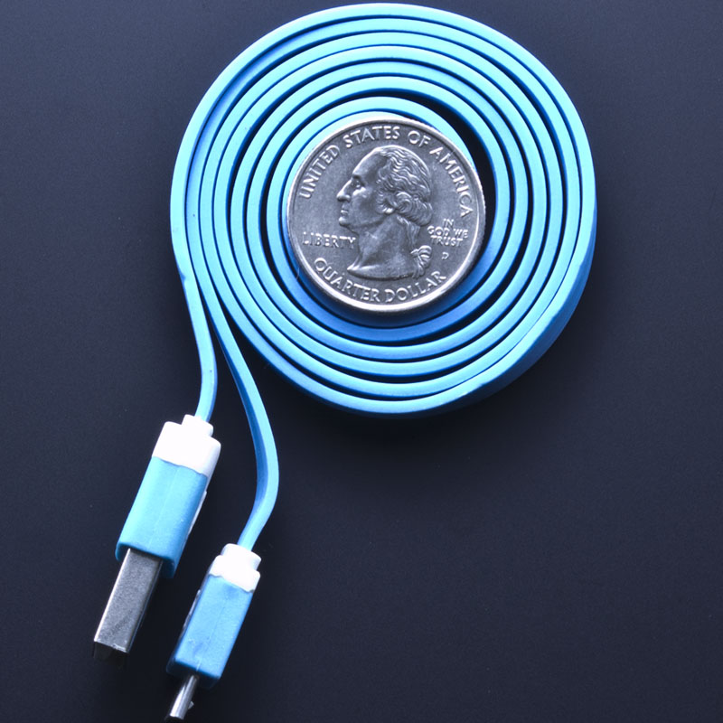
1 × USB-A to Micro-B Cable Male/Male (3ft)
1 × 0.96" 128×64 pixels OLED Screen
Setting Up the ESP8266


We've written a detailed instructable with all the steps needed to get your ESP8266 configured and ready for programming using the Arduino IDE:
We also have a video guide available here:
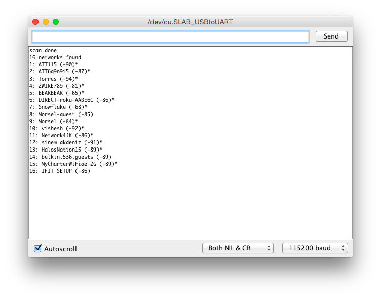
Maker sure you follow the steps carefully, and that at the end of the setup you're able to select the correct board and port from the "Tools" menu option!
Wiring the OLED Display

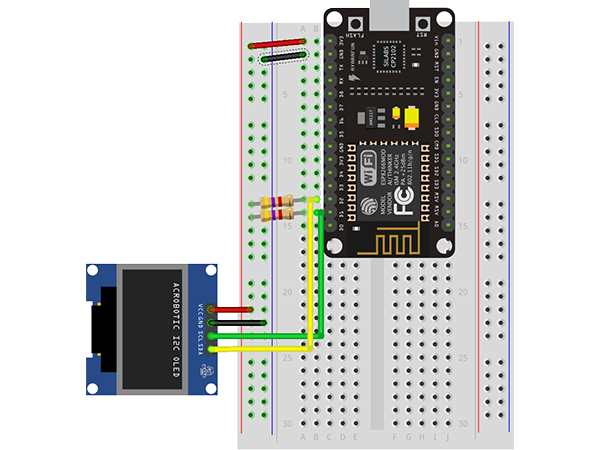
Wiring the two is straight-forward, keeping in mind that we need 2 4.7KΩ resistors to pull up the I2C lines. The I2C pins on the DevKit board are GPIO4 for SDA (labeled D2) and GPIO5 for SCL (labeled D1), this we wire them to the corresponding pins on the OLED screen PCB as shown in the diagram below:
Using the default I2C pins for the ESP8266 allows us to simply use the built-in Wire library for I2C communication. With everything wired up, it's time to test some code.
Installing Additional Libraries

There are a few different ways to install a library in the Arduino IDE. For detailed, step-by-step instructions on all the different ways to do so please visit our tutorial. The simplest method is to use the built-in library manager in the Arduino IDE. It can be accessed via the menu option Sketch → Include Library → Manage Libraries…
In the search field enter:
- "ACROBOTIC OLED" and install the resulting option.
- "Arduino JSON" and install the resulting option.
That's all that's needed, we can now dive straight into the code.
Code Walkthrough: Crypto Tracker

The very first thing we do is forget about the OLED screen and simply figure out how to get the data that we'll eventually display on it. We use the Serial Monitor for printing out the data, and worry about the OLED later.
To get the data we first try to find where is it freely available. A Google Search reveals 2 popular services we can use, CoinMarketCap and Coindesk. Looking through their APIs let us know that we can access the current price for different cryptocurrencies by sending a GET request to:
- CoinMarketCap using https://api.coinmarketcap.com/v1/ticker/bitcoin/
- Coindesk using https://api.coindesk.com/v1/bpi/currentprice.json
If we simply point our browser to either of the URLs we'll see the data that we're after. However, to do so with the ESP8266, we need to first connect to the internet, and then use a web client.
Although both services work great, we'll stick with Coindesk for this project.
1. Connecting to the internet
Using the built-in ESP8266WiFi.h library, we use the begin method of the WiFi object with a couple of character arrays as arguments, which contain the credential to the network.
const char* ssid = "YOUR_SSID";
const char* password = "YOUR_PASSWORD";

WiFi.begin(ssid, password);

while (WiFi.status() != WL_CONNECTED)
{
  delay(500);   Serial.print(".");
}
As is typical, we do this inside the setup() function. Also, we use a while() loop to monitor the state of the connection. The loop runs until the connection is successful, though this blindly assumes that the network is available–a way to make the code more robust would be to handle cases where the connection isn't successful.
2. Using a web client
Using the built-in ESP8266WiFi.h library, we create an instance of the WiFiClient class, set up the request we're going to send to the Coindesk server, and declare the buffer where we'll store the server's response.
We also construct the request we're going to send to the server, specifying a minimum set of header fields that are needed.
#define CD_API "/v1/bpi/currentprice.json"
#define CD_URL "api.coindesk.com"

WiFiClient client;
static char respBuffer[4096];

const char request[] =
  "GET " CD_API " HTTP/1.1\r\n"
  "User-Agent: ESP8266/0.1\r\n"
  "Accept: */*\r\n"
  "Host: " CD_URL "\r\n"
  "Connection: close\r\n"
  "\r\n";
Next, we attempt to connect to the host site using the connect() method of the WiFiClient object. We do some basic error handling if the connection isn't successful, but once again we assume it will be successful.
Using the print() method of the WiFiClient object (not to be confused with its counterpart from the Serial class), we send the request. We then close and flush the connection, and we also wait an arbitrary-but-reasonable amount of time (1 second) for the server to respond.
Once the server responds, we use a while() loop to load the response into our character buffer. To do this, we use the read() method of the WiFiClient object.
if (!client.connect(CD_URL, 80))
{<br> Serial.println("Connection failed");
    return;
}
client.print(request);<br>client.flush(); delay(1000);<br>uint16_t index = 0; while(client.connected())<br>{<br>  if(client.available())<br>  {<br>    respBuffer[index++] = client.read();<br>    delay(1);<br>  }<br>}
By the design of the API to which we send the request, we know that the response from the server will be formatted in JSON.
Parsing JSON-formatted data
Although we know that the data is formatted in JSON, is we print out the character buffer we notice that there's some extra characters in the server's response. For this reason we use the strchr() method to trim the buffer (creating a new one) all the way to the first opening curly brace '{' where we know, by inspection, that the JSON-formatted data begins.
char * json = strchr(respBuffer,'{');

DynamicJsonBuffer jBuffer;
JsonObject& root = jBuffer.parseObject(json);
Serial.println("JsonObject: ");
root.prettyPrintTo(Serial);
Serial.println();

JsonObject& bpi = root["bpi"];
JsonObject& usd = bpi["USD"];
String tmp = usd["rate_float"];
data = tmp;

Serial.print("BTC/USD:");<br>Serial.println(data);
Using the fantastic ArduinoJson library we can now parse the data. We can do so by creating either a Static or Dynamic JsonBuffer object (we chose the later), and calling its respective parseData() method. The JsonBuffer object(s) then allow us to pick the data we want by using the familiar keyed array notation.
For now, we can visualize the data in the Serial Monitor using the print() method of the Serial object (remember to initialize it in the setup() function!). But, the next step is to send it over to the OLED screen.
Displaying the data
Although several libraries exist (including our own!) for working with OLED screens, we chose to follow our quick-n-dirty standalone OLED demo:
As such, we created a helper file util.h containing a few constants including the font data. Please note that the file should be located in the same folder as the .ino sketch.
Then, it was a matter of creating a few low-level helper functions for setting up the OLED screen, and communicating with it. And one high-level function to print the data we wanted:
setTextXY(0,0);     // Set cursor 0th page (row), 0th column
displayString("BTC/USD:");


void printData(String data)
{
  setTextXY(2,0);
  displayString("setTextXY(0,0);     // Set cursor 0th page (row), 0th column
displayString("BTC/USD:");


void printData(String data)
{
  setTextXY(2,0);
  displayString("$");
  setTextXY(2,1);
  char __data[sizeof(data)];
  data.toCharArray(__data, sizeof(__data));
  displayString(__data);
}
quot;);<br>  setTextXY(2,1);
  char __data[sizeof(data)];
  data.toCharArray(__data, sizeof(__data));
  displayString(__data);
}
We also encapsulated the data capture and parsing inside a getData() function, and the data displaying on the OLED screen inside the prinData() function. These two functions are called from within the standard loop() function every 10 seconds.
The prototype's firmware files are available at: