Build a Hi-Fi STK4191II Stereo Amplifier With Bass and Treble Control
by LongTechnical in Circuits > Speakers
24 Views, 0 Favorites, 0 Comments
Build a Hi-Fi STK4191II Stereo Amplifier With Bass and Treble Control
Hello, friends!
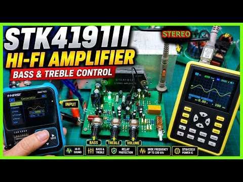
In this project, I'll show you how to build a Hi-Fi stereo amplifier based on the STK4191II power amplifier IC. The amplifier includes independent Volume, Bass, and Treble controls, making it suitable for home audio systems, DIY speakers, or workshop sound systems.
One feature I really like about this design is its excellent frequency response. During testing, I used a signal generator and an oscilloscope to verify the circuit, and the amplifier maintained a clean sine wave even at 100 kilohertz.
The circuit is simple to assemble, performs very well, and is an excellent project for anyone interested in DIY audio electronics.
All of the PCB boards shown in this project were manufactured by JLCPCB.
Supplies
Electronic Components
- STK4191II (or another compatible STK41xx series IC)
- PCB board
- Resistors
- Ceramic capacitors
- Electrolytic capacitors
- Diodes
- 7812 voltage regulator
- Relay
- Transistors (according to the schematic)
- LEDs
- 100-kilohm potentiometers ×3 (Volume, Bass, Treble)
- Input and output connectors
- Power connector
- Large heatsink
- Thermal compound
- Screws and insulating hardware for the STK IC
Tools
- Soldering iron
- Solder wire
- Digital multimeter
- Oscilloscope
- Signal generator
- Wire cutters
- Small screwdriver
- DC power supply
Download the Project Files
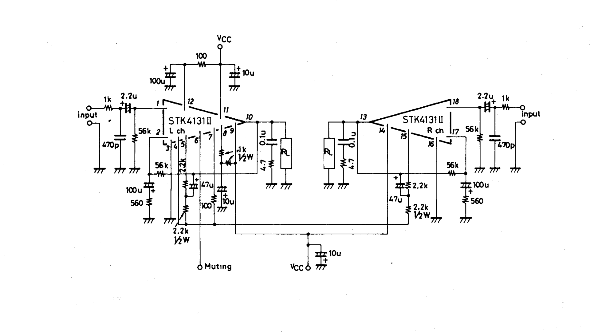
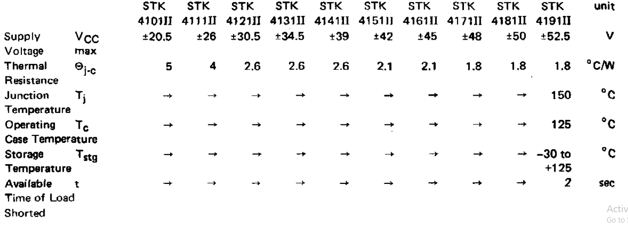
All project files are available in the video description.
The download package includes:
- Schematic
- PCB board files
- Gerber files
- Bill of Materials (BOM)
You can order the PCB board directly from the Gerber files
Order the PCB Board
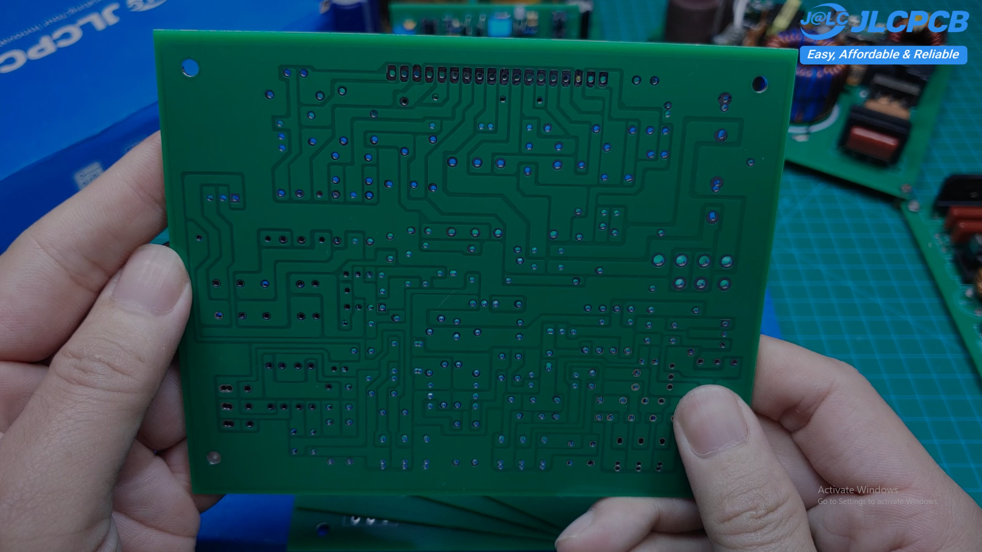
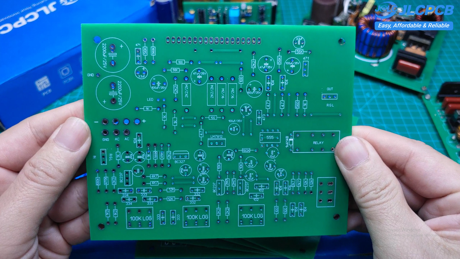
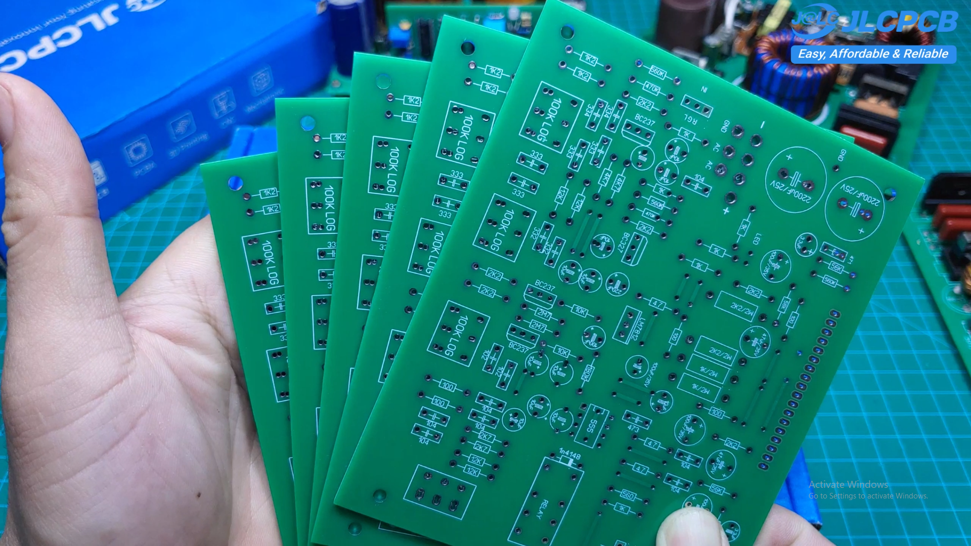
For this project, I ordered the PCB board from JLCPCB.
The manufacturing quality is excellent.
The silkscreen is clear and easy to read, the solder mask has a smooth finish, and the drilled holes are accurately aligned. The board arrived only one week after uploading the Gerber files, and I was very satisfied with the overall quality.
Assemble the Power Supply
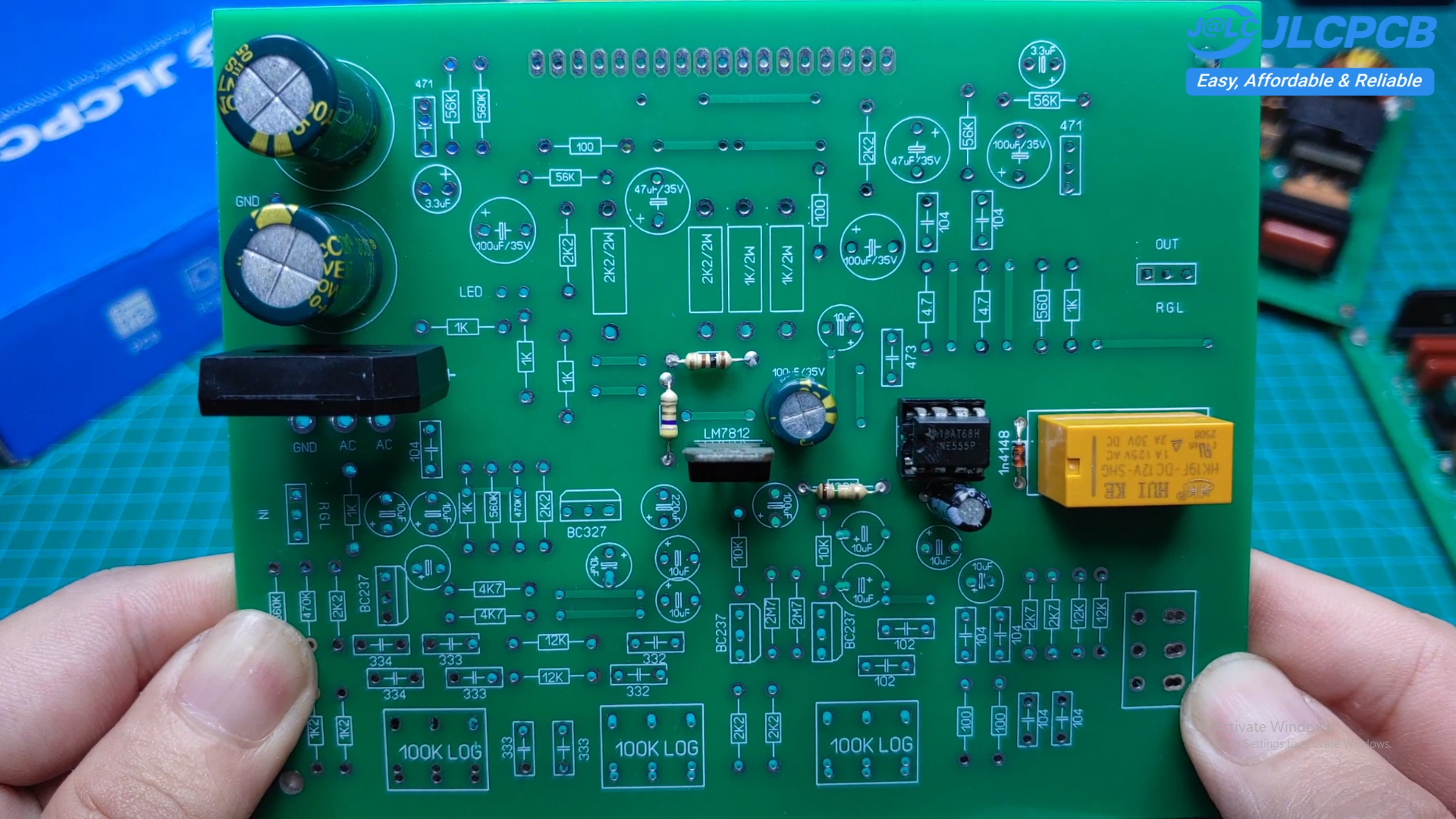
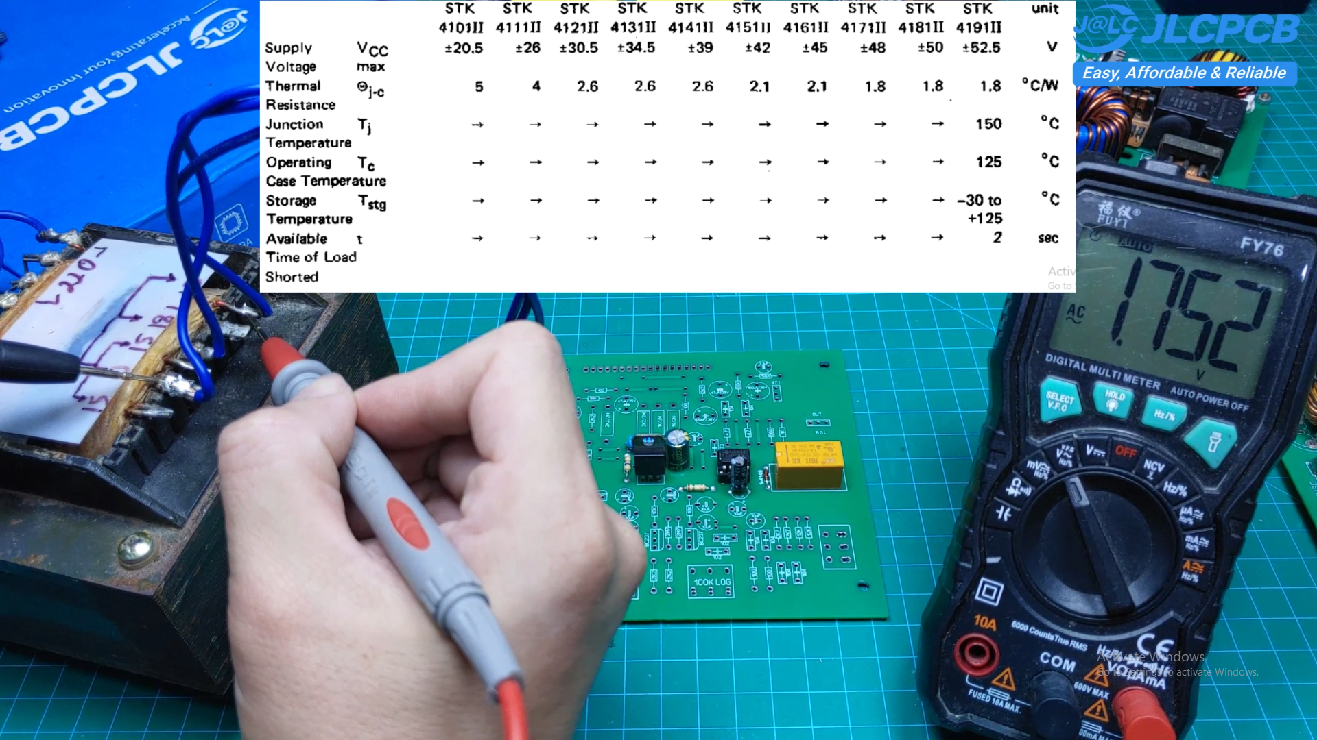
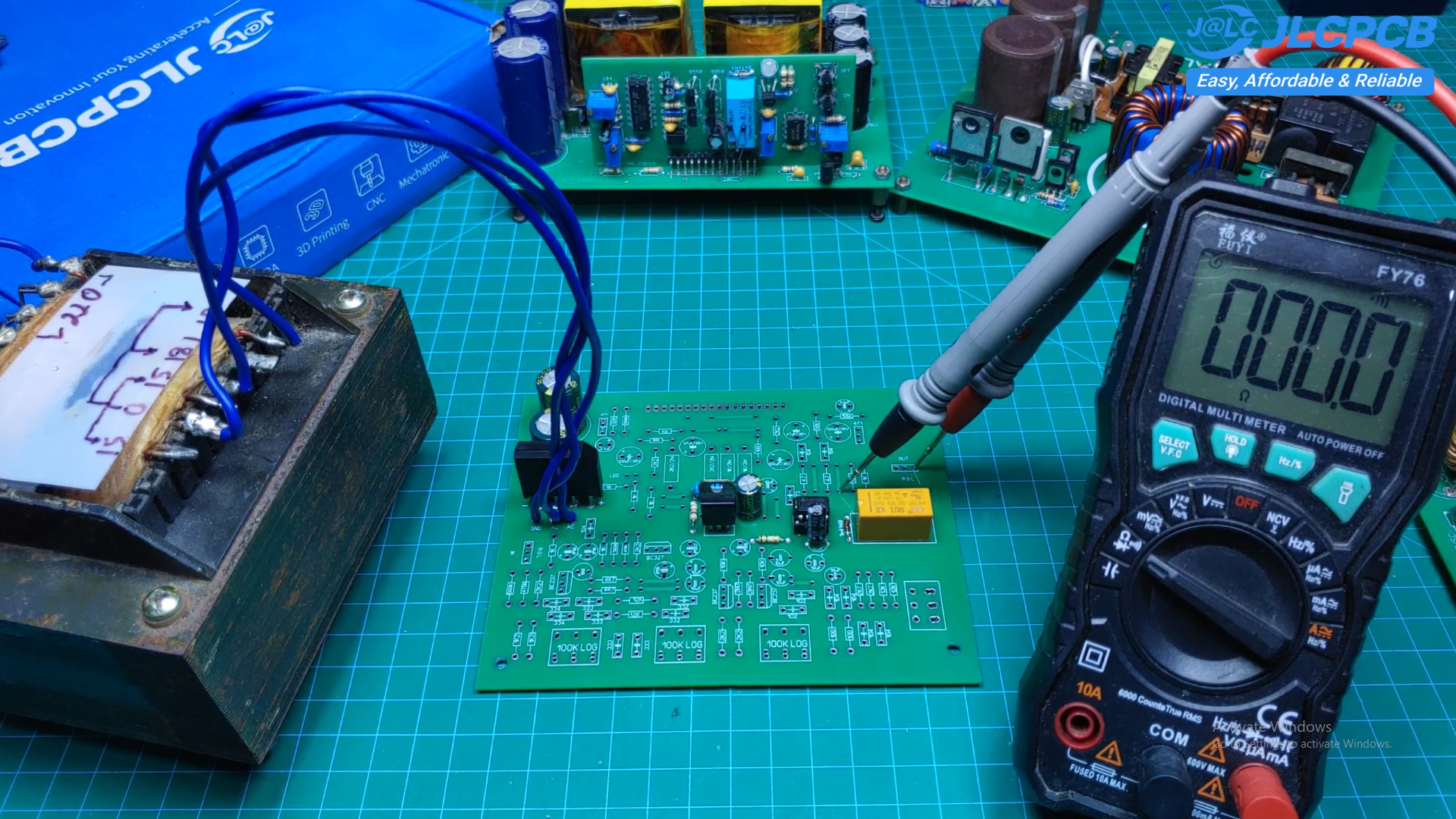
Begin by assembling the power supply section.
Install:
- Diodes
- Voltage regulator
- Filter capacitors
- Relay delay components
Double-check the polarity of every electrolytic capacitor before soldering.
Incorrect polarity may permanently damage the capacitor.
Install the Tone Control Components
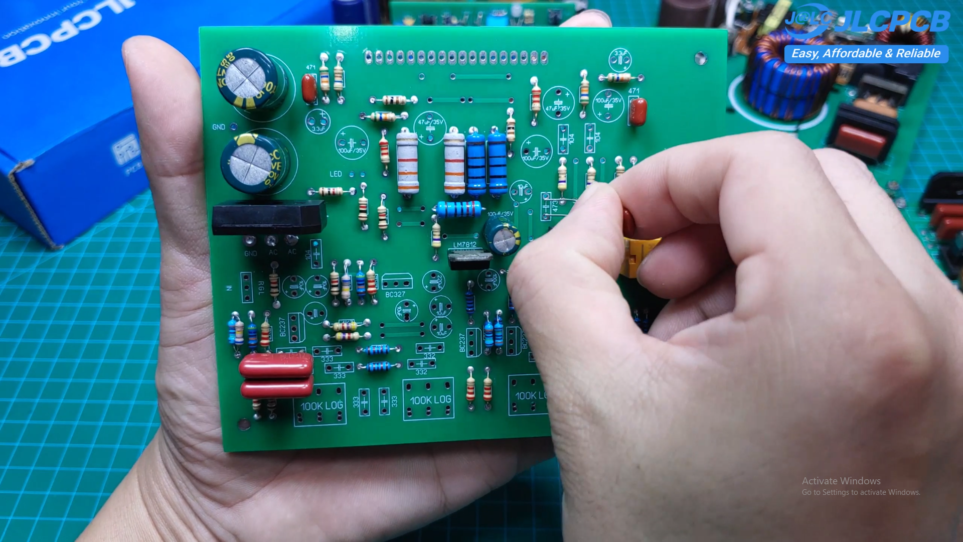
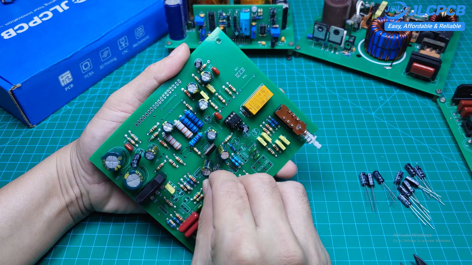
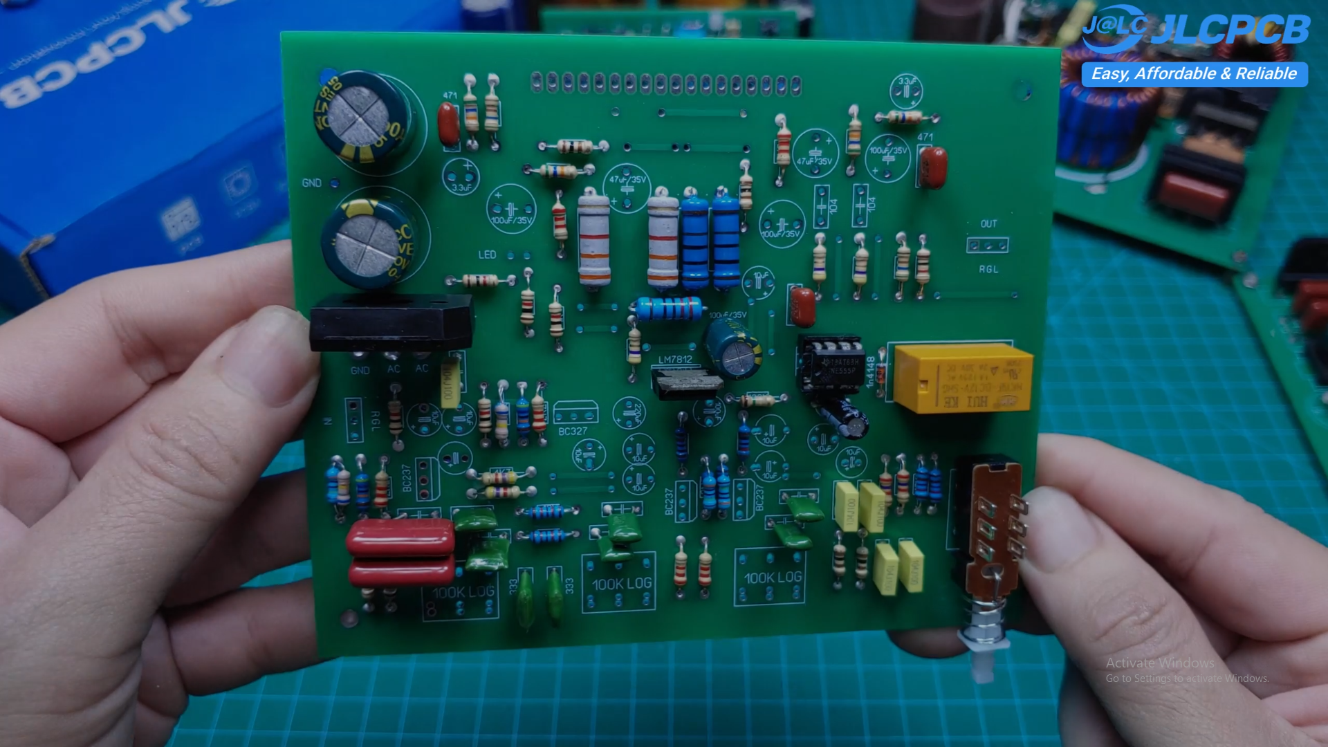
Next, install all resistors and the non-polarized capacitors.
These components form the Bass and Treble tone control circuit.
Be sure to install every component according to the values printed on the PCB board.
Even a small mistake can affect the frequency response.
Install the Potentiometers
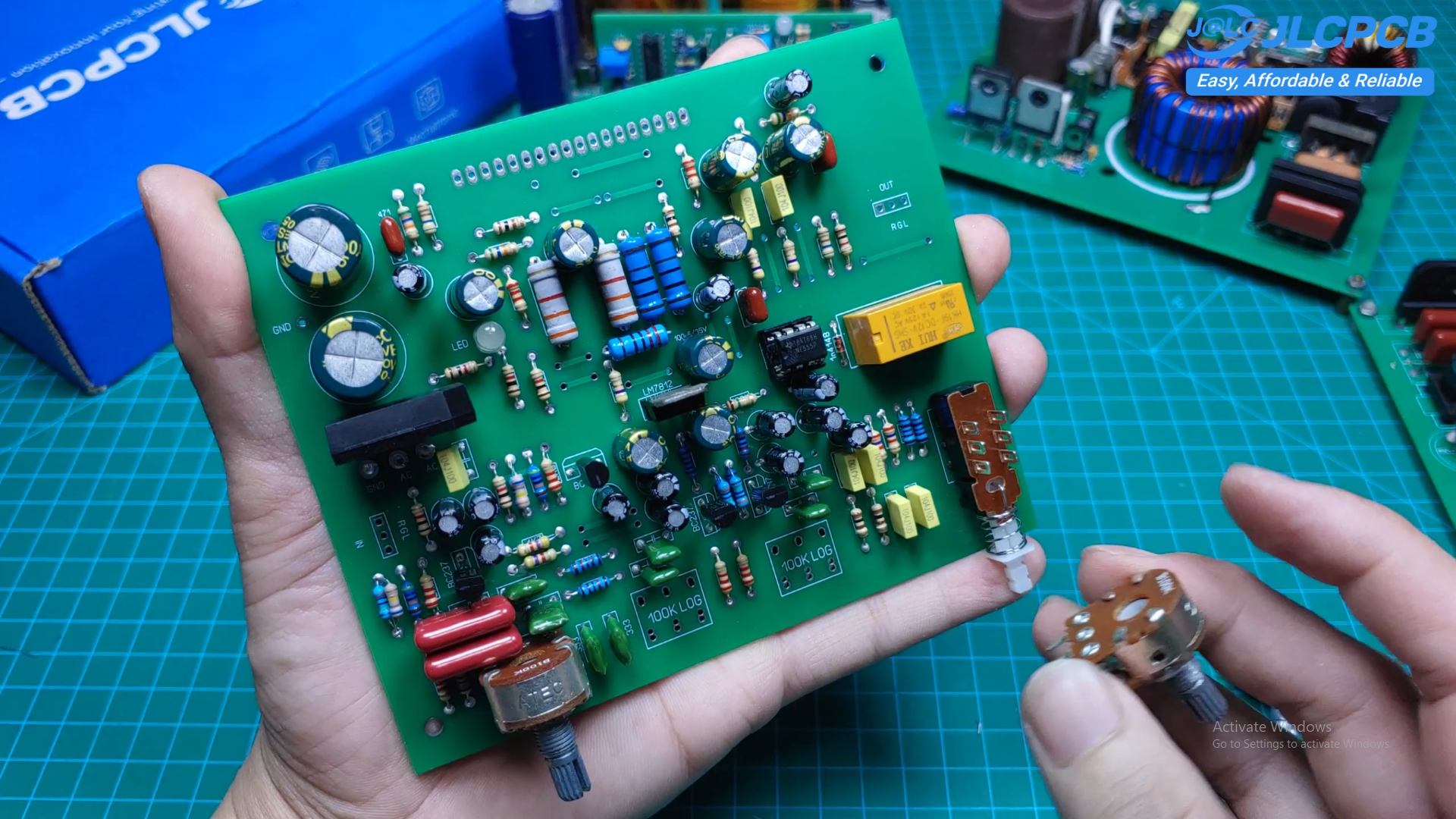
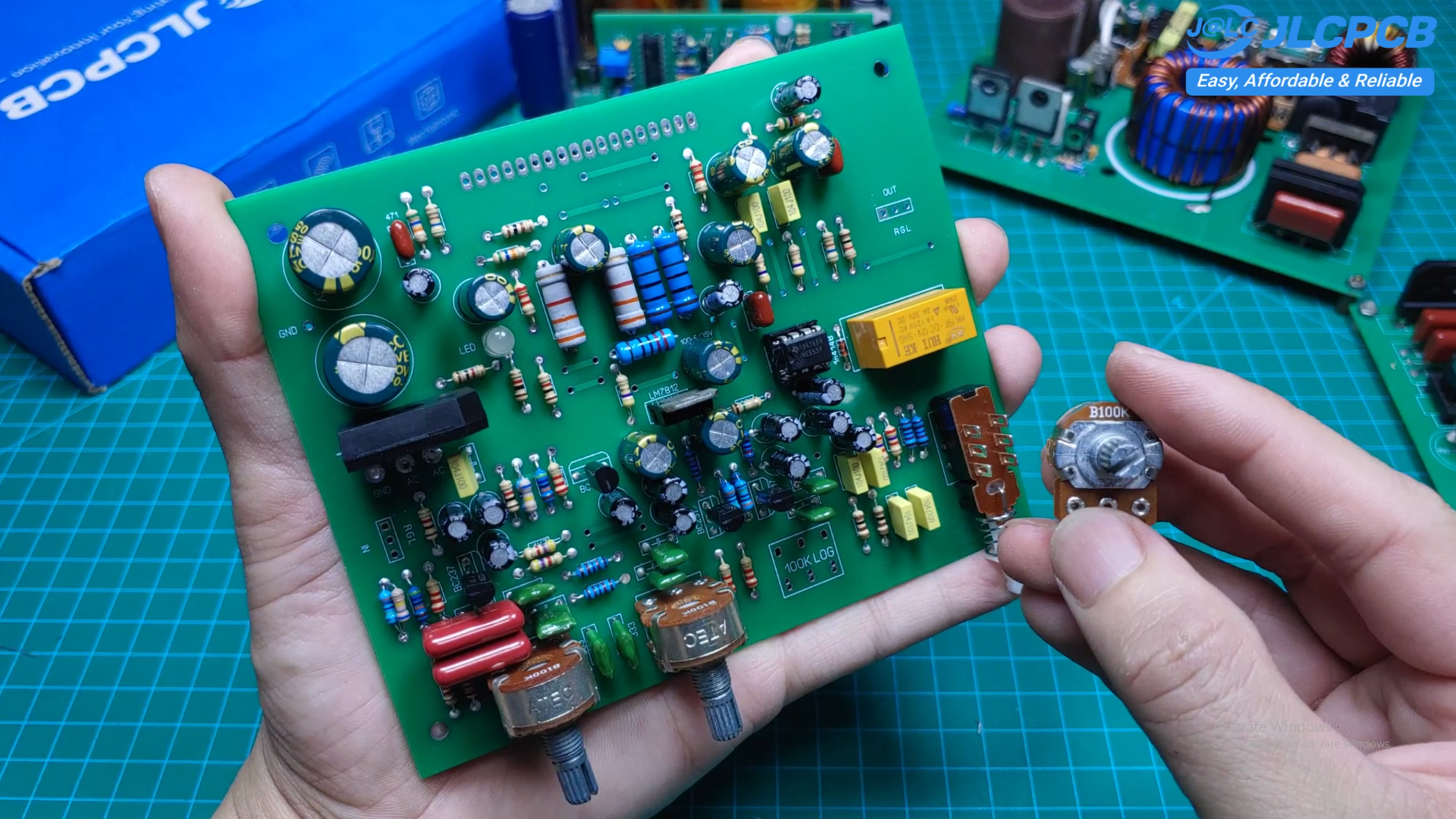
Install three 100-kilohm potentiometers.
They control:
- Volume
- Bass
- Treble
Take your time to align them correctly before soldering.
Test the Circuit Before Installing the STK41xx IC
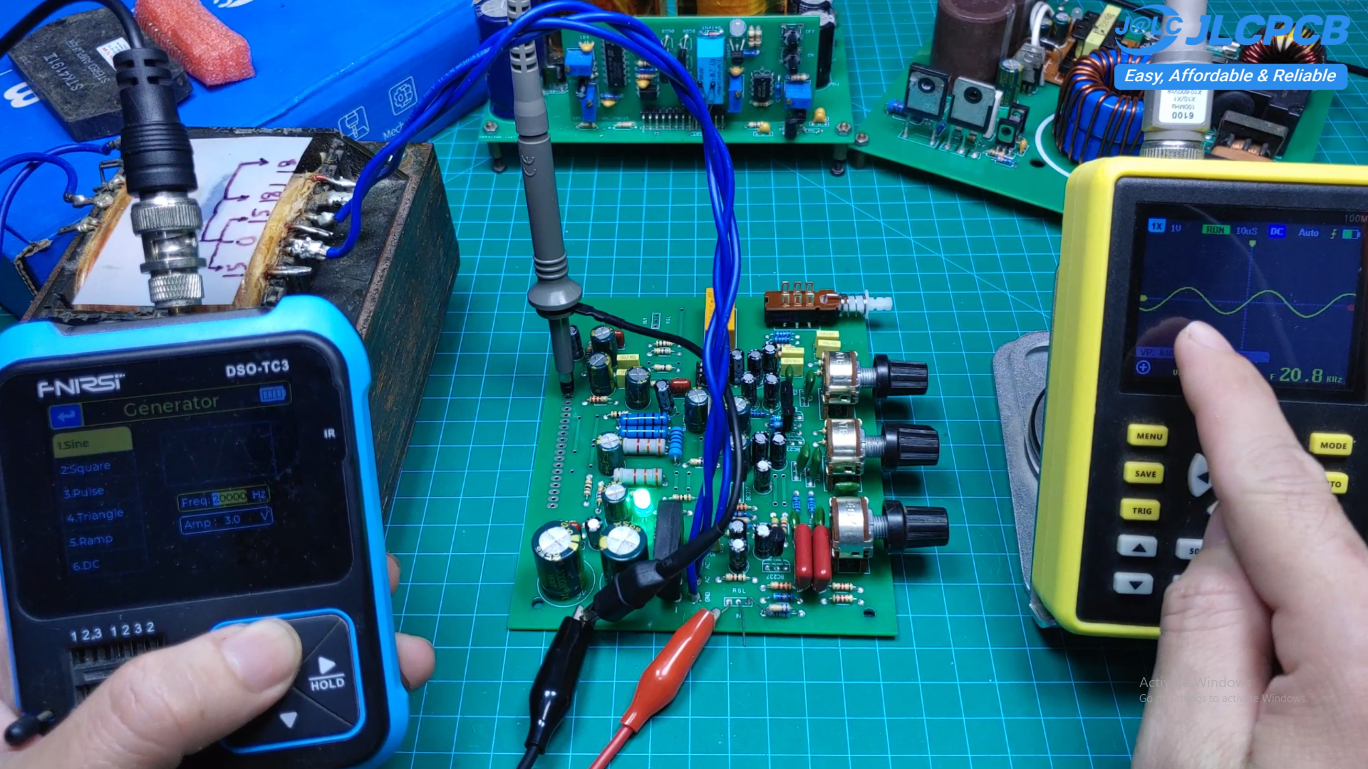
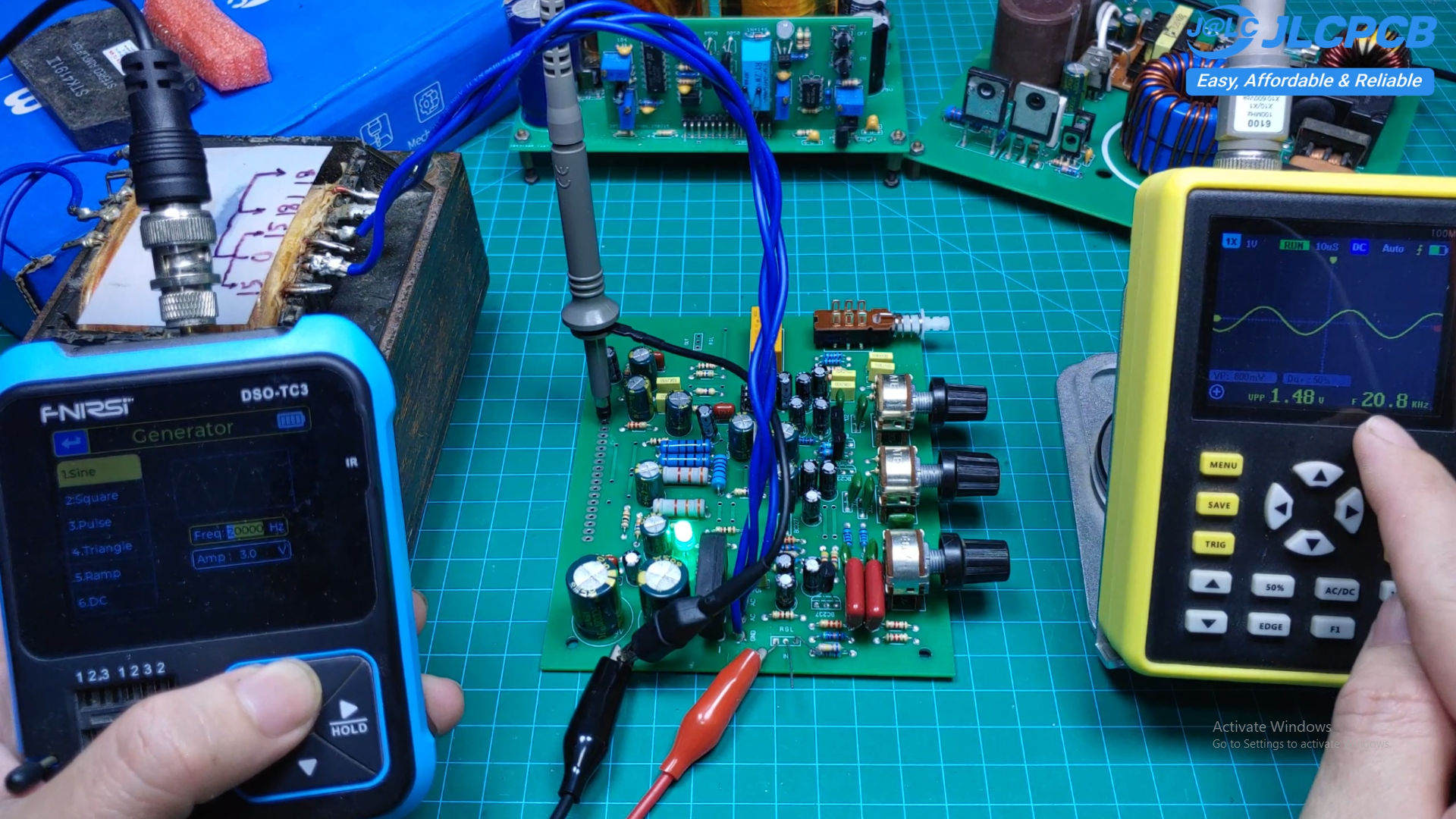
This is one of the most important steps.
Do not install the STK41xx IC immediately after assembly.
Instead:
- Apply power to the circuit.
- Verify the output of the 7812 regulator is approximately 12 volts.
- Check that the relay activates after a short delay.
- Confirm that no component becomes excessively hot.
Performing these checks greatly reduces the risk of damaging the power amplifier IC.
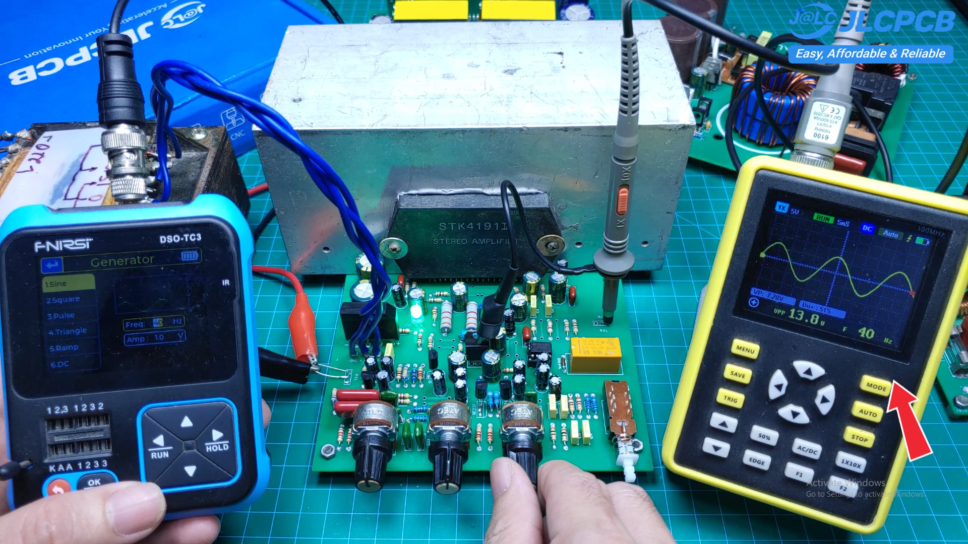
To verify the circuit, connect a signal generator to the amplifier input.
Monitor the output using an oscilloscope.
As the input frequency increases, the waveform should remain clean and stable.
During my testing, the tone control circuit showed an excellent frequency response.
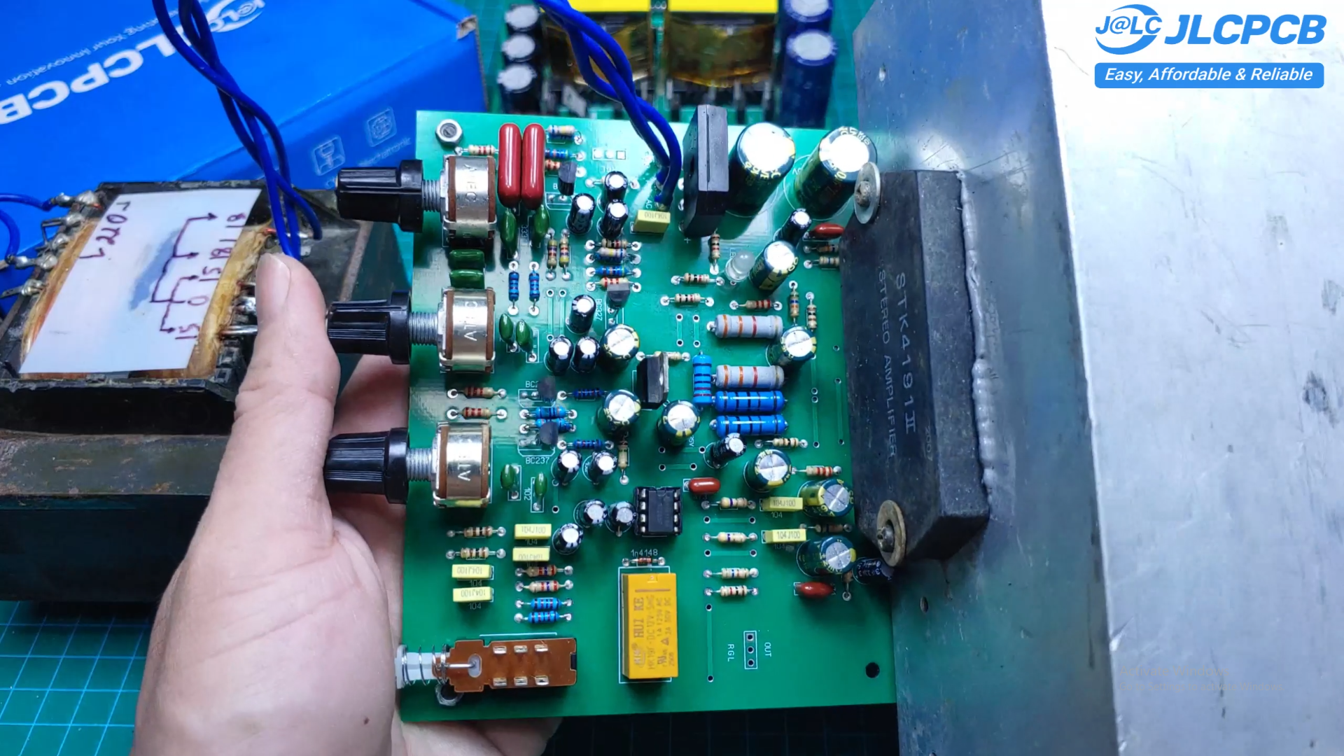
Install the STK4191II
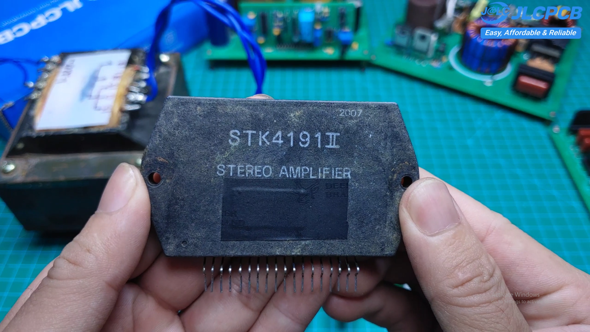
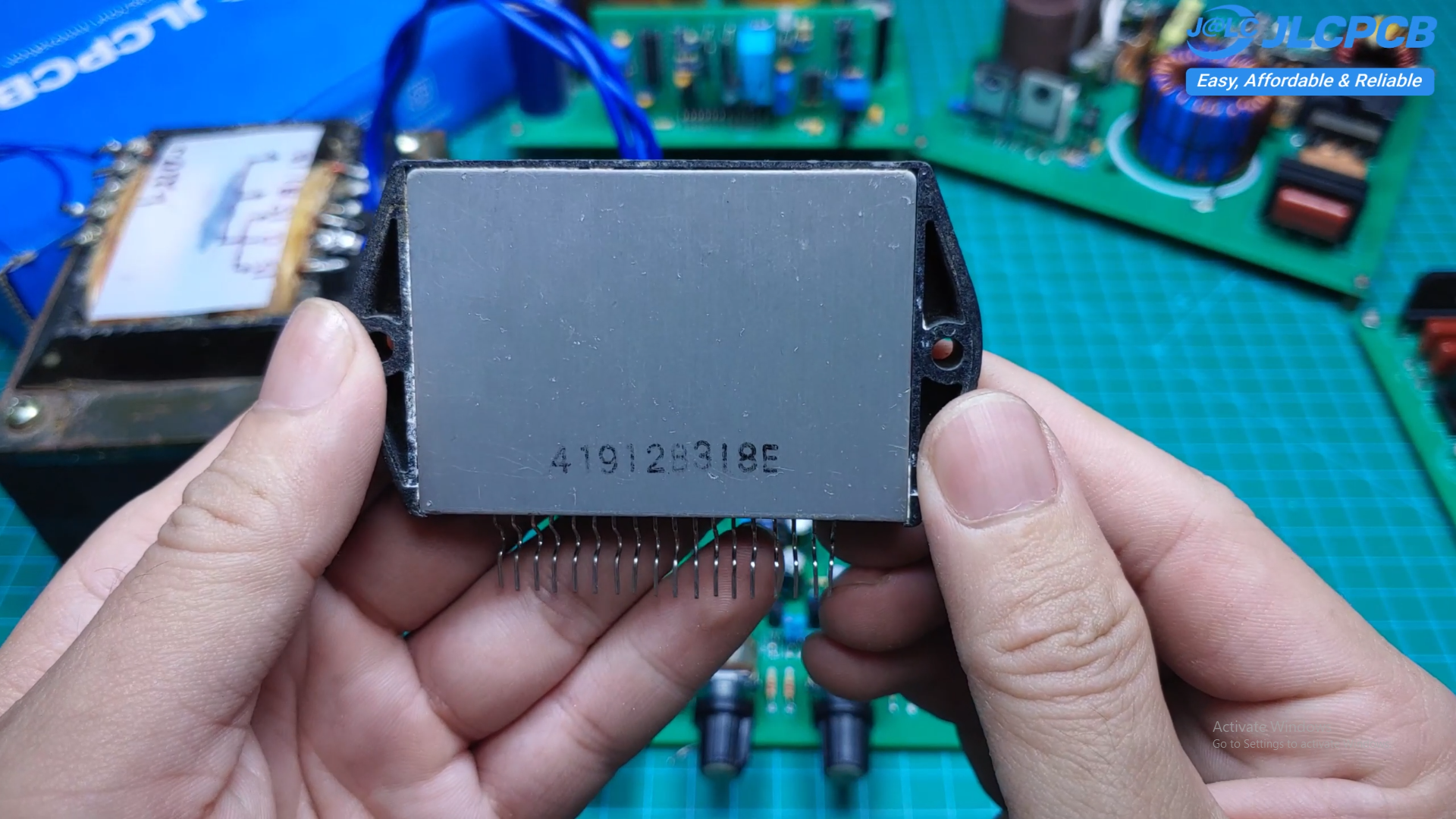
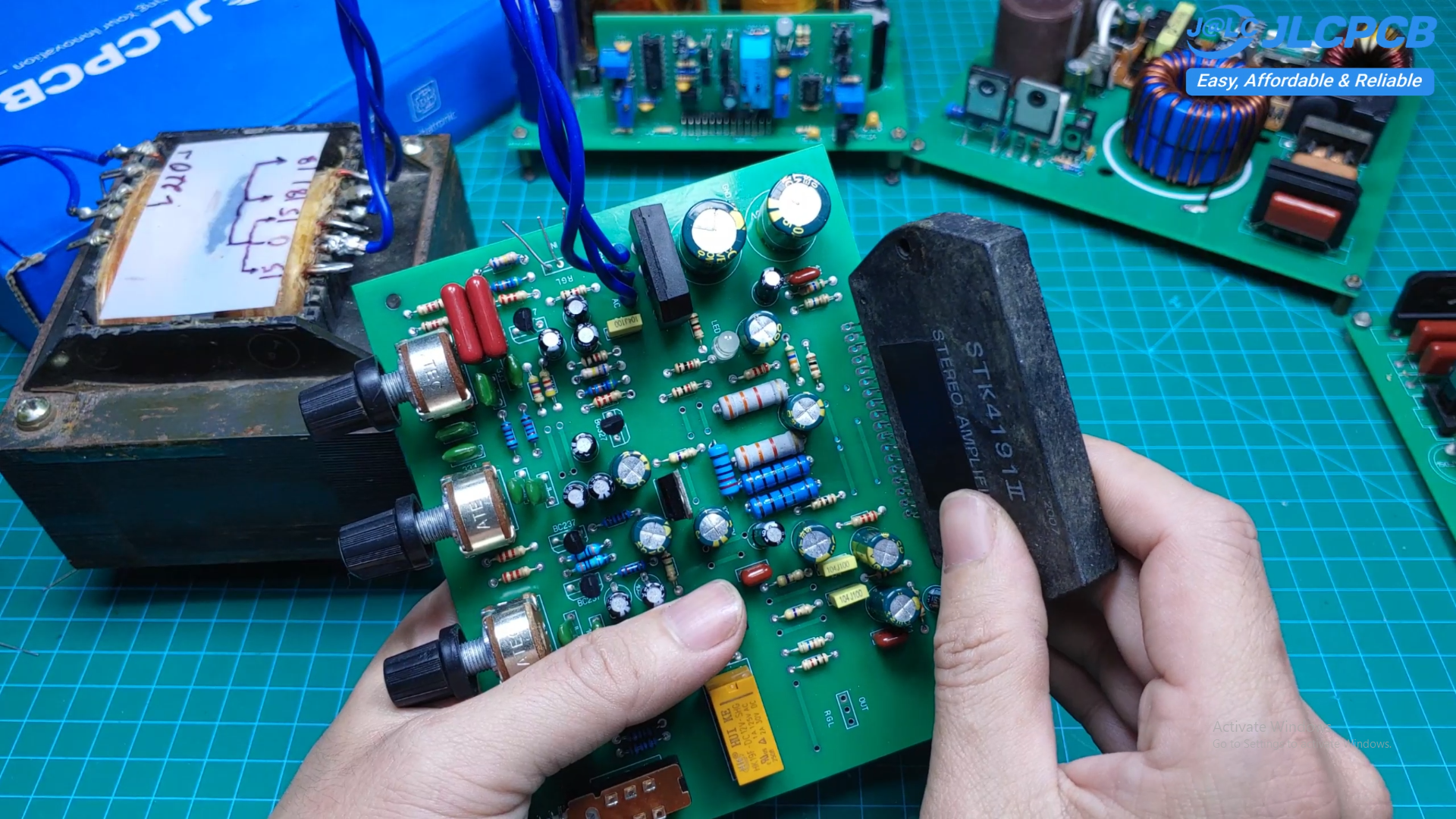
After confirming that the circuit operates correctly, install the STK4191II.
Handle the IC carefully.
The pins are small and numerous, so make sure every pin is properly aligned before inserting it into the socket.
Finally, mount the IC securely onto a large heatsink using thermal compound.
Good cooling is essential for reliable long-term operation.
Final Testing
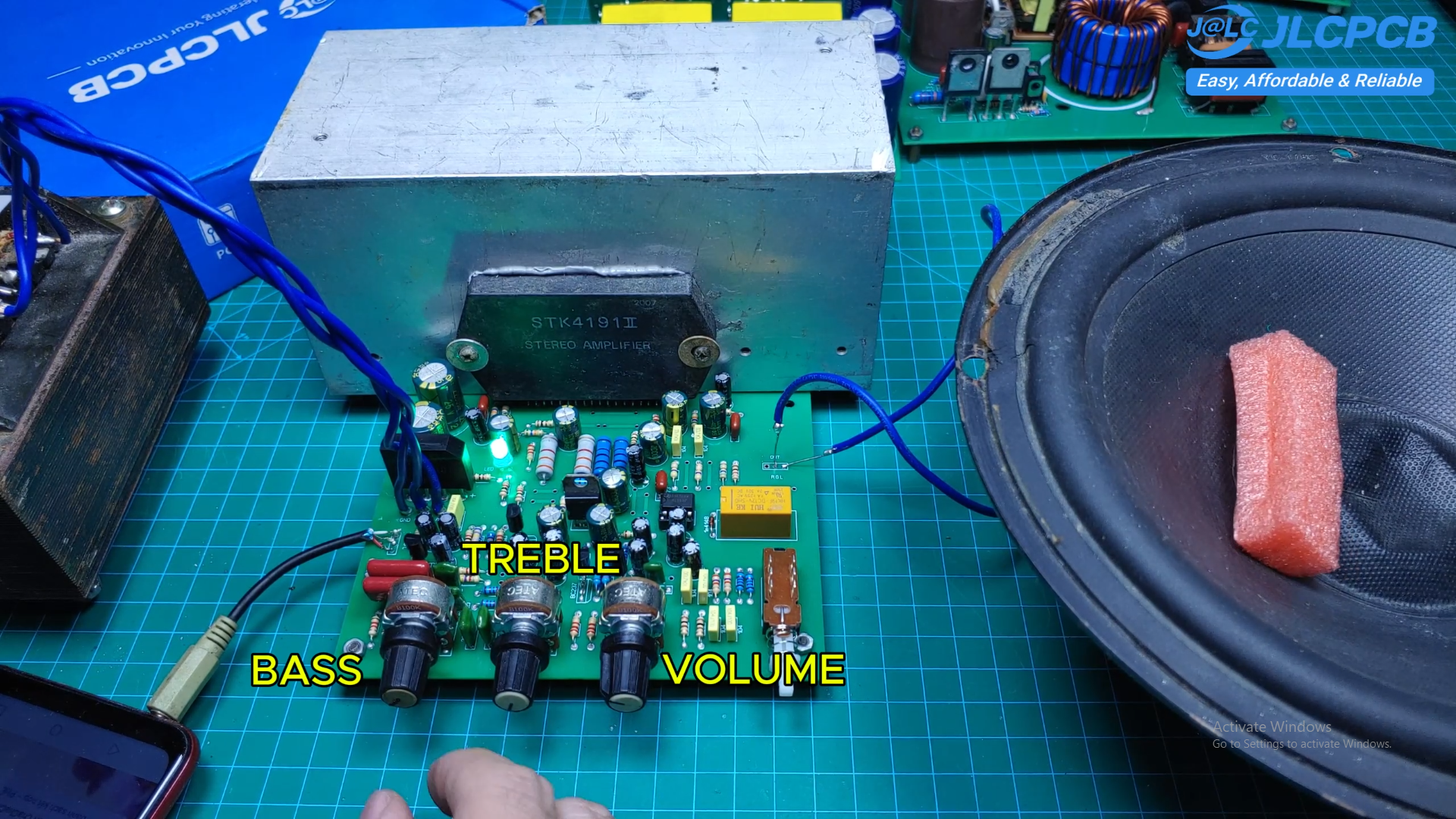
Power on the amplifier.
Connect an audio source and speakers.
Adjust the Volume, Bass, and Treble controls.
Then verify the amplifier using a signal generator and an oscilloscope.
Even at 100 kilohertz, the output waveform remained clean with virtually no visible distortion, demonstrating the excellent performance of this design.
This STK4191II amplifier is a reliable and enjoyable DIY audio project.
It offers:
- Excellent sound quality
- Smooth Bass and Treble adjustment
- Stable operation
- Simple construction
- Easy testing and troubleshooting
I hope this guide helps you build your own amplifier successfully.
If you make one, I'd love to see your results. Feel free to share your finished project or ask any questions in the comments.
Happy building!