Build a Lipo Battery Gauge
by JayconSystems in Circuits > Arduino
14923 Views, 121 Favorites, 0 Comments
Build a Lipo Battery Gauge

Are you ever surprised when your computer, or electronic project, suddenly shuts down because the battery died?
If so, then you might like the idea of a battery gauge. It establishes communication between the battery and the user by determining the amount of charge remaining in the battery. This allows you to know when the battery is low so that you will be able to save your work and charge your battery. That's if it's rechargeable.
This tutorial is going to generally explain how the Li-battery, the Micro-USB LiPo charger, the LED bar, and the code work together.
Materials
To make this project, you will need the following materials:
Jumper Wires (different colors)
10Ω Resistor (Brown, Black, Black)
About the Li-battery
Same as the other types of batteries, Li-battery is used to store and release energy at the desired time.
This type of battery is a member of the rechargeable battery family composed of a chemical component known as lithium. This battery can last 2-3 times longer than an alkaline battery, which is the most popular battery type.
Li-batteries are mostly used in wireless systems because of their performance under extreme temperature.
Some of the parameters we need to know about the battery are as follows:
Voltage:
- We say the battery is full when the voltage is 4.2. While we consider the battery empty when it reads below 3.2V. Do not let the battery exceed the maximum voltage value since it might explode. Discharging a battery below the minimum voltage value might cause damage to it and might be hard to recharge it again.
Capacity:
- Batteries are rated according to current capacity. Current capacity determines how fast the battery would discharge in certain conditions and it’s expressed as mili ampere-hours (mAh).
Q = I x t , where Q is capacity, I is current and t is time.
C-rate:
- Specifies the current used to charge and discharge a battery. For example, 1000mAh battery would provide 1000mA current for one hour if the rate is 1C. The same battery discharging at 0.5C rate would provide 500mA for two hours.
Temperature:
- Within a temperature range of 5 to 45 degrees C, a Li-battery shows good charging performance. If the temperature is not within the range, it would degrade the performance of the battery or results in slower charging time.
About the Li-battery - Charging


Charging happens when Li- ion moves from positive to negative electrodes carrying a current with the help of external power source. The charging time for the battery might vary depending on how much current is supplied by the external power, or the LiPo charger. Looking at the charging curve image above, we can see that there is a charging procedure (constant current and constant voltage) that we need to keep in mind.
The first few hours can be described as a constant current phase while the voltage slowly rises. When the voltage reaches its peak, which is around 4.2V, the constant voltage phase begins. During this phase, we can see that the current starts to decline toward zero while the voltage is kept constant. Note that charging terminates when the current is below 3% of the set threshold.
To estimate how long a battery will take to charge fully, we can use the formula seen in the second image above.
About the Li-battery - Discharging


Discharging happens when Li- ion moves from negative to positive electrodes carrying a current. Depending on how much the load draws current from the battery, the discharging time can vary. Also, because Li-batteries can provide high energy densities, they have a fairly flat discharging curve compared to other types of batteries.
We can estimate how long it will take to discharge a Li-battery with certain current capacity. First we need to know the load that is going to be attached to the battery, and then use the equation seen in the second image above to calculate the time.
About the Li-battery in This Tutorial


In this tutorial we used a 30mAh battery capacity with a load that requires 20mA, so we can estimate the total time it takes for the battery to discharge completely.
A LiPo-Charger is a Micro-USB lithium battery charger based on MCP73831 IC from Microchip. It will charge a Li-battery at a rate of 30mA, but can be increased to accommodate bigger batteries by swapping out the 34.8k resistor that is connected at PROG on the Microchip.
The third image above is how you can find the specific resistor value for specific current capacity rate for the battery. Refer to the data sheet for more information.
About the Li-battery in This Tutorial - Continued

In this tutorial, we used a 30mA Li-Battery so the Programmable Resistor should be 33.3 kiloohms, as shown in the formula above.
This LED bar is made up of 6 segments. It is used to display the power of the battery with each LED representing the level of the battery. It has in total 8 pins, which 6 of them are for the LED and the rest are to power up the bar. Note that the LED bar works with 5V and draws 5mA from the power source.
Hardware Assembly
1. Place a black and red wire on the breadboard. Connect the red wire to 5V on the Arduino while the black wire is connected to the GND.
Hardware Assembly - Continued

2. Place each LED on the breadboard as shown in the picture. Connect the longer pin of each LED in serious with the resistor while the shorter pin to the ground. Note that the LEDs are connected in parallel.
Hardware Assembly - Continued

3. Place jumper wires on the +ve and –ve pin on the LiPo Charger. Connect the +ve pin from the LiPo charger to any pin on the breadboard then connect another wire in series from that pin to the analog pin of the Arduino (A0). Connect the –ve pin to the ground on the breadboard. Last connect the Li-battery to the LiPo charger.
Hardware Assembly - Continued

4. Place the 6-Segment LED Bar on the breadboard then connect the VCC to 5V and GND to the ground.
Connect the rest of the pins from the LED Bar to the Arduino as follows:
- Pin A => Pin 2
- Pin B => Pin 3
- Pin C => Pin 4
- Pin D => Pin 5
- Pin E => Pin 6
- Pin F => Pin 7
Software Program
<p>// declaring the pin that is used in this project<br>int pin_A=2; // LED bar pin
int pin_B=3;
int pin_C=4;
int pin_D=5;
int pin_E=6;
int pin_F=7;
int pot = 0; // pin that would read from battery</p><p>void setup() {
  // decalaring the input and output pins
Serial.begin(9600);// serial communication between Arduino and computer
pinMode(pin_A, OUTPUT);
pinMode(pin_B, OUTPUT);
pinMode(pin_C, OUTPUT);
pinMode(pin_D, OUTPUT);
pinMode(pin_E, OUTPUT);
pinMode(pin_F, OUTPUT);
pinMode(10,OUTPUT);
pinMode(11,OUTPUT);
}</p><p>void loop() {</p><p>int level = analogRead(pot); //  reading value from the battery
int led1 = analogRead(10);
int led2 = analogRead(11);
// multiplying the value with voltage resolution of the Arduino board
float real_voltage = level * 0.004882814;
Serial.println("");
Serial.print("Current Voltage: ");// displaying on the serial monitor
Serial.println(real_voltage);

/*depending on the value read from the battery, we turn on the LED to show
the level of the battery */
if (real_voltage < 3.69)
{
  digitalWrite(pin_A, HIGH);
  digitalWrite(pin_B, HIGH);
  digitalWrite(pin_C, HIGH);
  digitalWrite(pin_D, HIGH) ;
  digitalWrite(pin_E, HIGH);
  digitalWrite(pin_F, HIGH);
  Serial.println("battery is off");
  delay(1000);
 }
else if (real_voltage >= 3.69 && real_voltage < 3.71)
{
  digitalWrite(pin_A, LOW);
  digitalWrite(pin_B, LOW);
  delay(1000);
  digitalWrite(pin_B,HIGH );
  delay(1000);
  digitalWrite(pin_C, HIGH);
  digitalWrite(pin_D, HIGH) ;
  digitalWrite(pin_E, HIGH);
  digitalWrite(pin_F, HIGH);
  Serial.println("Battery is 5%");
  delay(1000);
 }
 else if (real_voltage >= 3.71 && real_voltage < 3.73)
{
  digitalWrite(pin_A, LOW);
  digitalWrite(pin_B, LOW);
  digitalWrite(pin_C, HIGH);
  digitalWrite(pin_D, HIGH) ;
  digitalWrite(pin_E, HIGH);
  digitalWrite(pin_F, HIGH);
  Serial.println("battery is 15%");
  delay(1000);
 }
 else if (real_voltage >= 3.73 && real_voltage = 3.75 && real_voltage < 3.80)
{
  digitalWrite(pin_A, LOW);
  digitalWrite(pin_B, LOW);
  digitalWrite(pin_C, LOW);
  digitalWrite(pin_D, LOW) ;
  digitalWrite(pin_E, HIGH);
  digitalWrite(pin_F, HIGH);
  Serial.println("battery is 50% full");
  delay(1000);
 }
 else if (real_voltage >= 3.80 && real_voltage < 3.88)
{
  digitalWrite(pin_A, LOW);
  digitalWrite(pin_B, LOW);
  digitalWrite(pin_C, LOW);
  digitalWrite(pin_D, LOW) ;
  digitalWrite(pin_E, LOW);
  digitalWrite(pin_F, HIGH);
  Serial.println("battery is 75 % full");
  delay(1000);
 }
 else if (real_voltage >= 3.88)
{
  digitalWrite(pin_A, LOW);
  digitalWrite(pin_B, LOW);
  digitalWrite(pin_C, LOW);
  digitalWrite(pin_D, LOW) ;
  digitalWrite(pin_E, LOW);
  digitalWrite(pin_F, LOW);
  Serial.println("Battery is Full");
  delay(1000);
 }
}</p>
Code Explanation

The first part of the code defines the global variable pin that is used by the LED bar and the LiPo charger. This pin can be used by any function declared in this program. Note that the LED is connected to a digital pin while the other are connected to an analog pin on the Arduino.
Inside the setup function we have opened a serial communication between the computer and the Arduino using a specific frequency band, which in this case is 9600. Then we defined which pin is used as an output or input. When we look at the loop function most of the main code resides in here. The first thing we did is to read the value from the LiPo charger and convert it into voltage. Note that the function analogRead() returns an integer value between 0 to 1023 since the Arduino board contains a 10 bit analog to digital converter (2^10 = 1024).
In order to map this 10 bit character read by the temperature sensor into analog value, we need to multiply the sensor value with the resolution of the Arduino board, which is approximately 0.0049( 5V/1024 units).
After getting the voltage value, we used a control structure like the “if statement” function to check whether the voltage is within certain range. Based on that range, we indicate the level of the battery by turning on the LEDs as well as display the percentage of the battery on the serial monitor, as seen in the images above.
When the battery level is at 5%, you will see the last LED on the bar blinking.
If you think that something is off, double check that there isn’t any misplaced code. Or check the battery level using a multimeter and compare it to the result from the code.
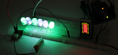
Results
In this tutorial, we tested the battery gauge using a load of 6 LEDs and a resistor.
In order to drain a 120mAh Li-battery within an hour, we connected the 6 LEDs parallel with a single resistor. Each LED can draw 20mA and have the same voltage drop across them.
Do not charge the battery while it’s being used without understanding the current limit of the battery and the load.
For example, if the chip (MCP73831) is programmed to limit current, which in our case 30mA and the load asks 100mA, the battery is not going to charge at all. This can be solved by load sharing, which is not discussed in this tutorial.
Also don’t apply current over 1C while charging.
In other words, if the battery is 120mAh, then it should not be charged over 120mA, otherwise it might explode.
Check out Jaycon Systems online store to purchase the materials you will need to recreate this Instructable.
If you have not done so already, check out Jaycon Systems other tutorials on our website as well as our other posts on Instructables.
If you have a question about this tutorial, please do not hesitate to post a comment, send us an email, or to post it in a thread on our forum.
Thanks for reading, and let us know how your project goes!