Build an Accessible Book Reader: a Raspberry Pi Scanner That Reads Printed Books Aloud
by lhm0 in Circuits > Raspberry Pi
23497 Views, 167 Favorites, 0 Comments
Build an Accessible Book Reader: a Raspberry Pi Scanner That Reads Printed Books Aloud
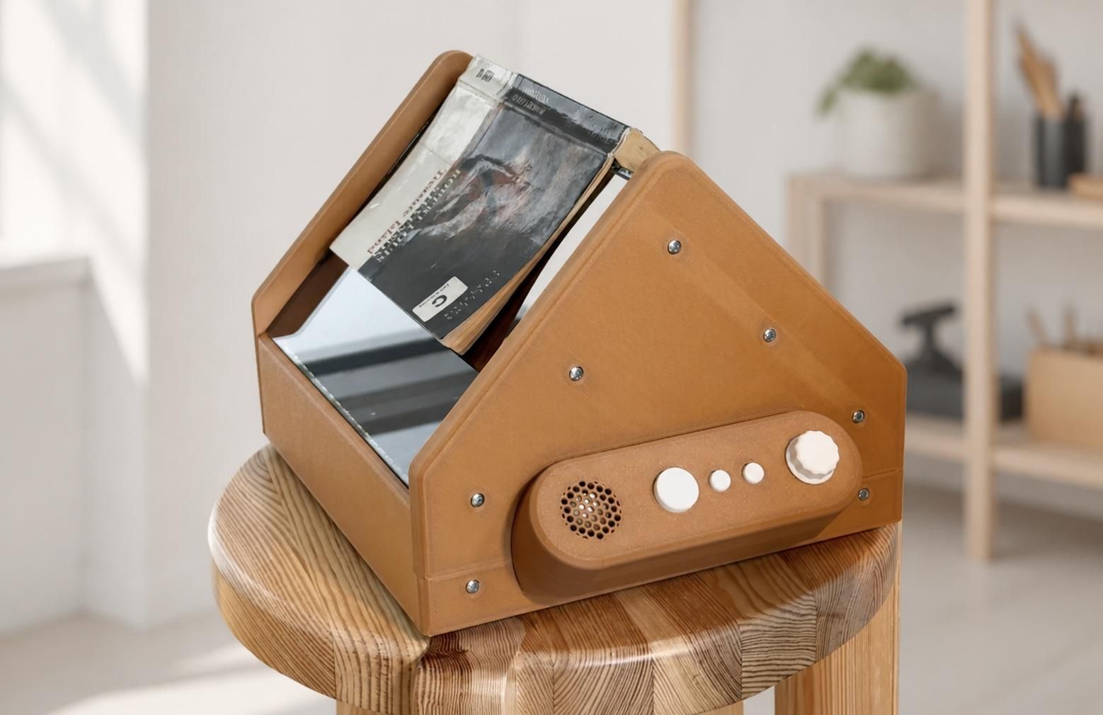


I built an open-source, open-hardware book scanner for blind and severely visually impaired people. It captures two printed pages, recognizes the text, and reads it aloud using text-to-speech. The device can be operated without a screen using only a few tactile controls.
I created it because printed books and screen-based reading systems can be difficult or impossible to use for people with severe visual impairments. The goal was to provide a simple and reliable way to make ordinary printed books accessible.
Supplies
The following list contains the main components of the Accessible Book Reader. A complete bill of materials, PCB design files, mechanical parts, software, and assembly documentation can be found in the GitHub repository:
https://github.com/lhm0/accessible_book_reader
Main components:
- 1 × Raspberry Pi 5
- 2 × Arducam 16 MP IMX519 camera modules B0449 with 120° diagonal wide-angle M12 lenses
- 2 × PN5180 NFC breakout boards
- 1 × Raspberry Pi Pico
- 1 × MAX98357A I²S audio amplifier breakout board
- Various custom PCBs
- 3D-printed enclosure and mechanical parts
- 2 × glass panels
Additional components such as LED strips, switches, connectors, wiring, fasteners, a loudspeaker, an encoder, NFC antennas, and power-supply components are also required. Please consult the repository for the current specifications before purchasing parts.
How the Accessible Book Reader Works
The Accessible Book Reader converts printed book pages into spoken audio. Its main functions are controlled by a Raspberry Pi 5, while the user operates the device using only a few tactile controls.
System Overview
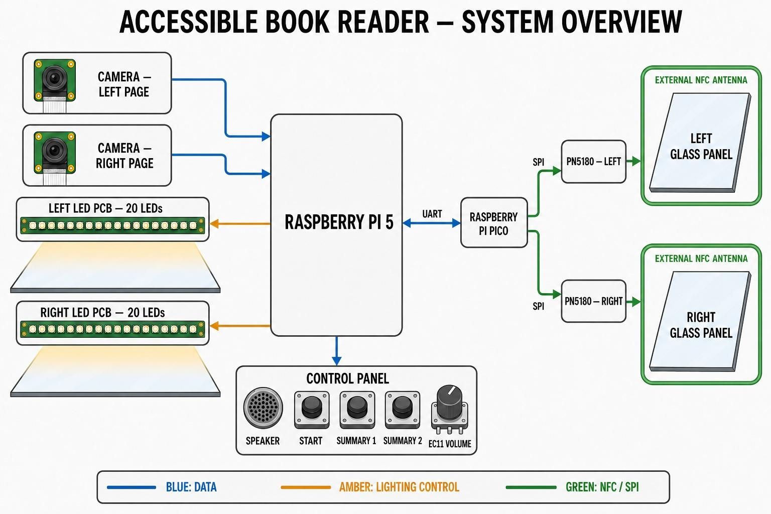
The first diagram shows the main hardware components. Two cameras photograph the left and right pages of the open book. Two custom LED boards, each equipped with 20 LEDs, illuminate the pages at a shallow angle. This provides even lighting while reducing reflections from the glass panels.
The Raspberry Pi 5 controls the cameras and lighting and performs the image processing and text recognition. The control panel contains the start button, two summary buttons, a rotary volume control and the speaker. Additional hardware used for identifying individual books is shown on the right and will be explained in a separate step.
From Button Press to Audio Output
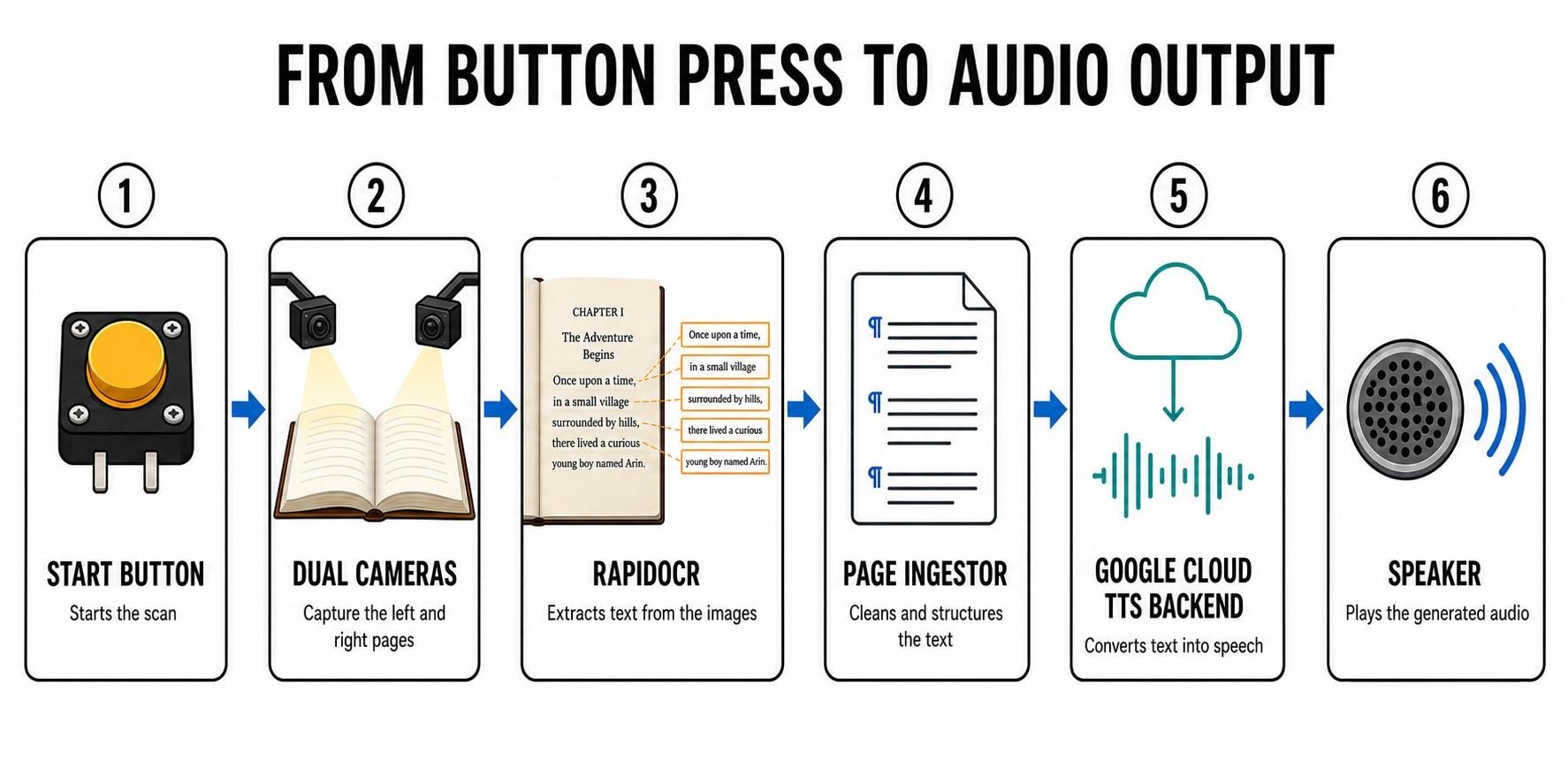
The second diagram shows the complete reading process.
Pressing the start button begins a new scan. The two cameras capture the left and right pages simultaneously. RapidOCR then extracts the printed text from the images.
The page ingestor cleans and structures the recognized text. Among other things, it removes word divisions, inserts appropriate pauses and handles sentences that continue onto the following page.
The prepared text is sent to the Google Cloud text-to-speech backend, which converts it into audio. The resulting audio is then played through the built-in speaker.
Creating Summaries
In addition to reading individual pages, the device can create spoken summaries of the scanned book.
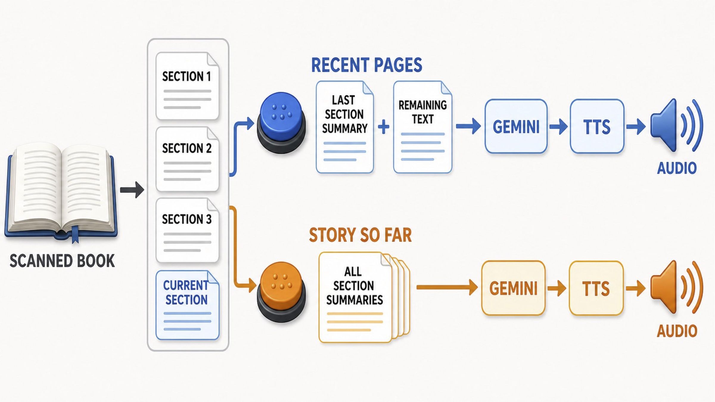
The stored pages are divided into sections of approximately 10 to 20 pages. Whenever possible, a section ends at a detected chapter boundary. Gemini generates and stores a summary for each completed section.
The Recent Pages button provides a summary of the most recently read content. If the current section is not yet complete, the device combines the last completed section summary with the remaining unsummarized text. Gemini condenses this information, and the result is converted into speech.
The Story So Far button creates an overview of the entire book up to the current position. For this purpose, all completed section summaries are combined in chronological order, condensed by Gemini and then read aloud using text-to-speech.
Book Compatibility, Languages and Identification
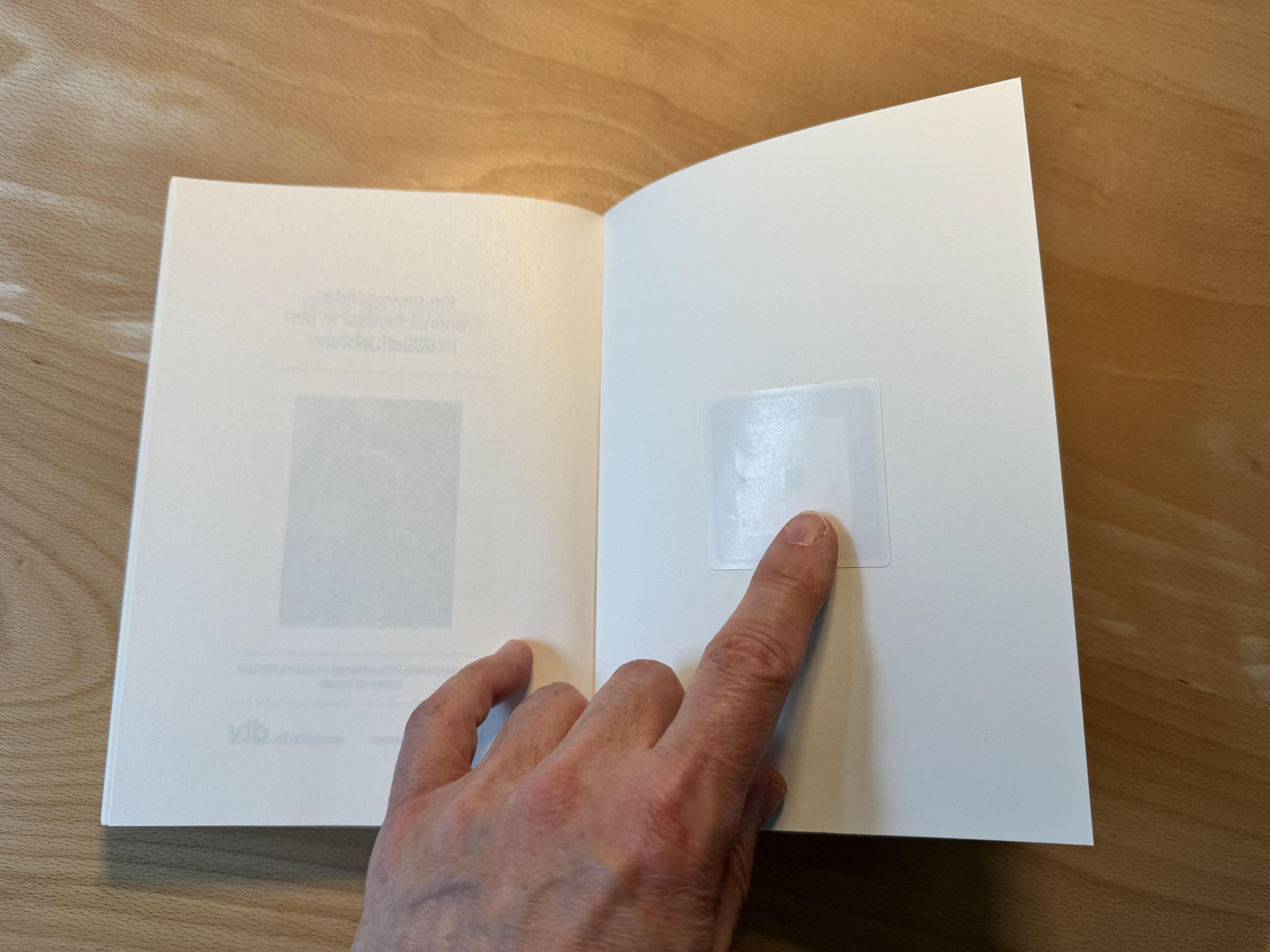
Before building the Accessible Book Reader, it is important to understand which books it can process and how individual books are identified.
Supported Languages
The current software supports German and English books. Other languages can generally be added, provided that they are supported by the OCR and text-to-speech services. However, adding another language requires corresponding changes to the software.
Book Size and Page Layout
The scanner can process book pages up to 160 × 240 mm.
The printed text should be at least 9 mm away from the center of the book, also known as the gutter. Text located closer to the center may be hidden by the curvature of the pages or fall outside the reliably captured area. This can be a limitation with some tightly bound paperback books that have very narrow inner margins.
NFC Tags and Book Identification
Each book must be equipped with an NFC tag. The unique ID stored in the tag is used as the book’s internal reference within the Accessible Book Reader.
Whenever pages are scanned, the recognized text is assigned to this reference. This allows the device to keep the content of different books separate. You can therefore switch between books and continue scanning later without mixing their pages or summaries.
The system supports both ISO 14443A and ISO 15693 tags. I recommend using ISO 15693 tags even though they are slightly more expensive. Their considerably greater reading range makes detection more reliable when the book is placed on the scanner.
Attach the NFC tag to the inside of the rear book cover, as shown in the photograph. Once installed, the tag can remain permanently attached to the book.
Print the Enclosure Parts
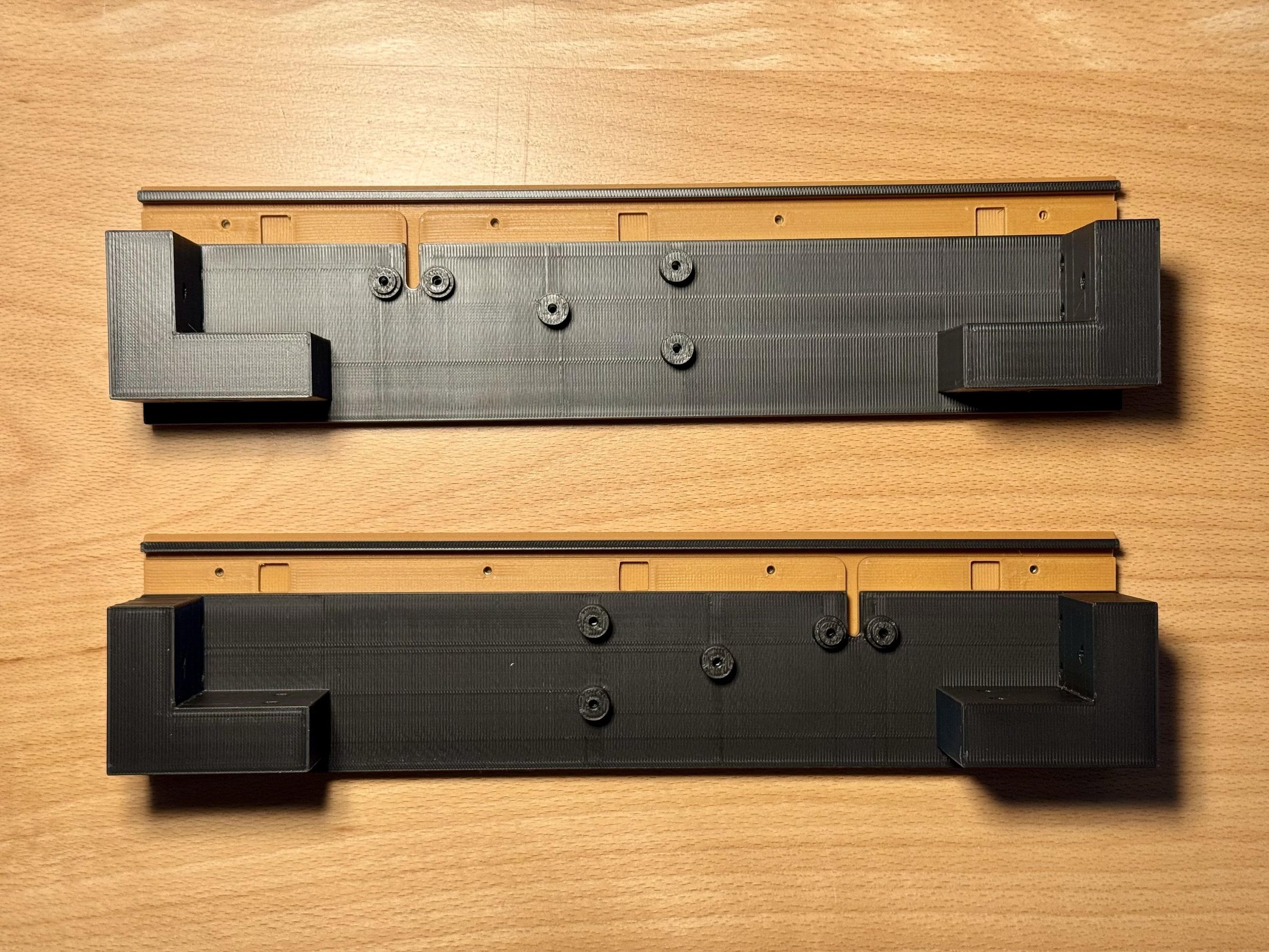
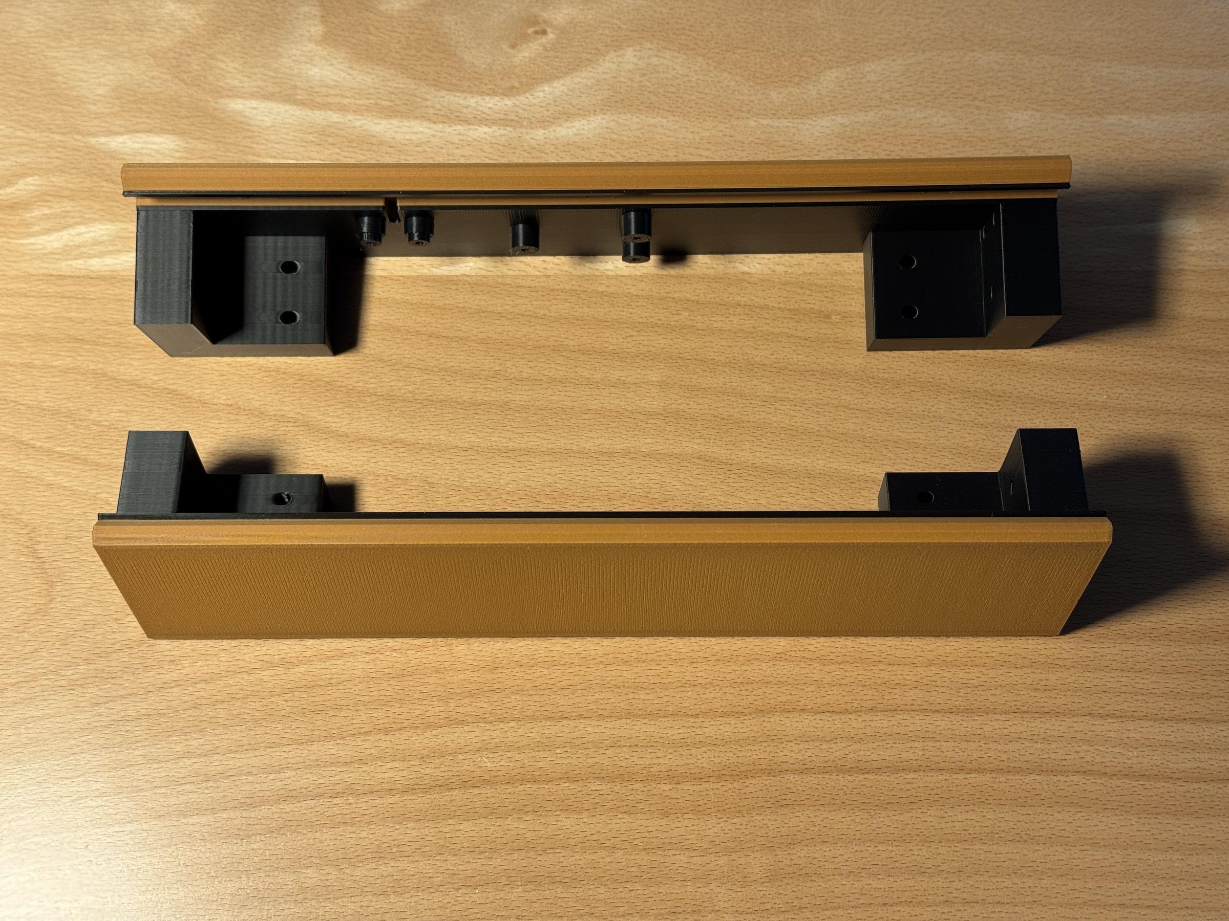
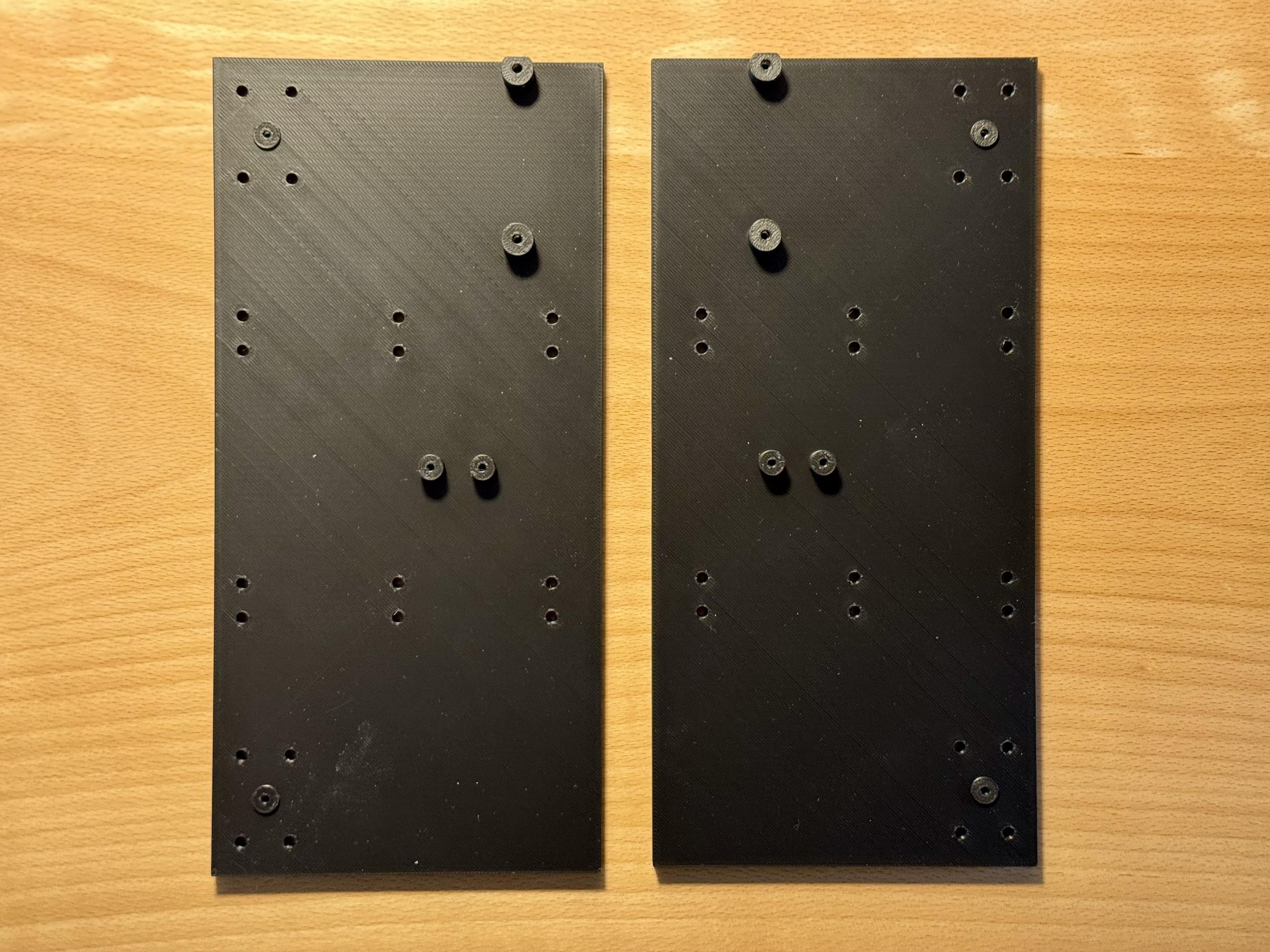
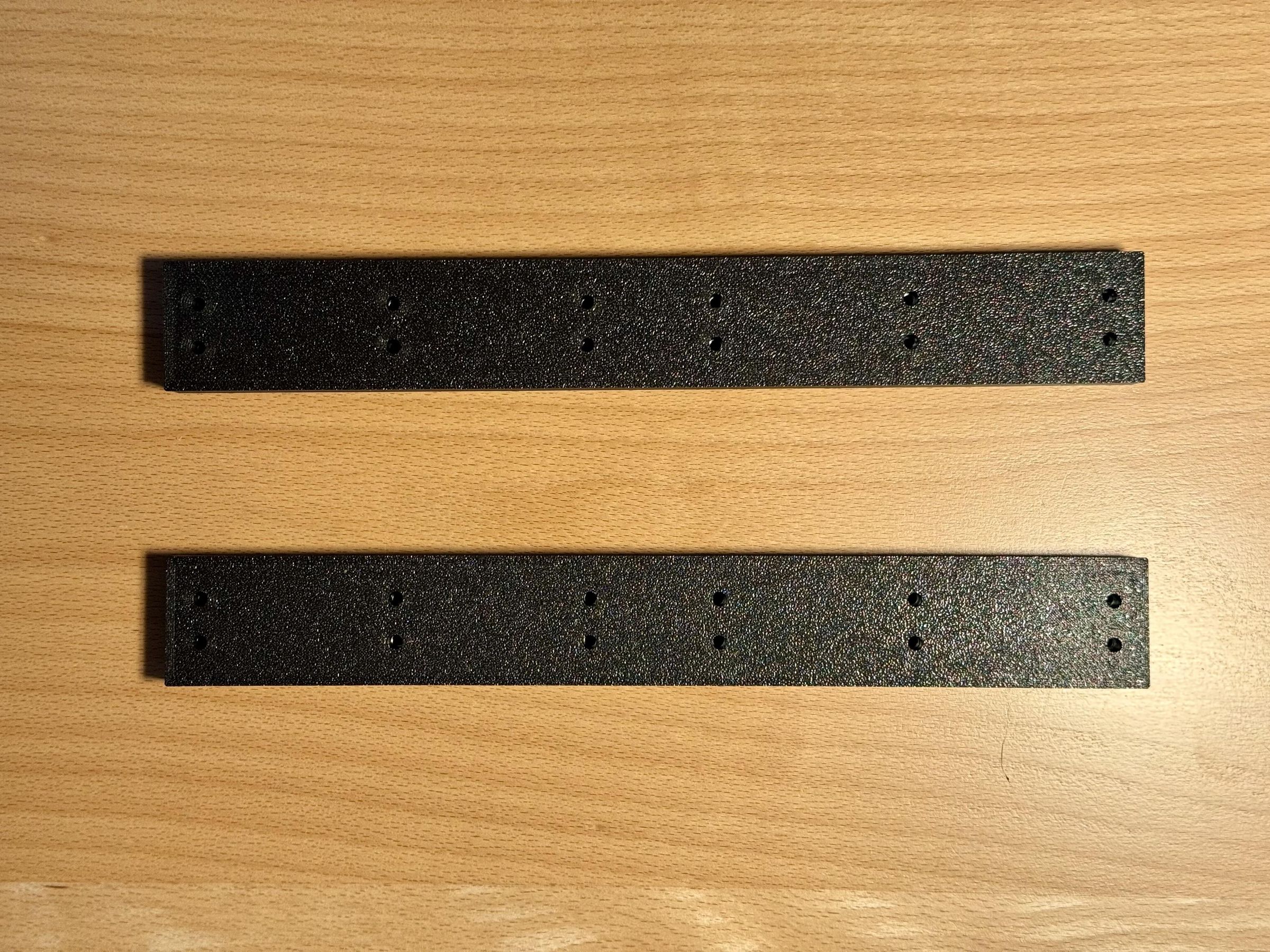
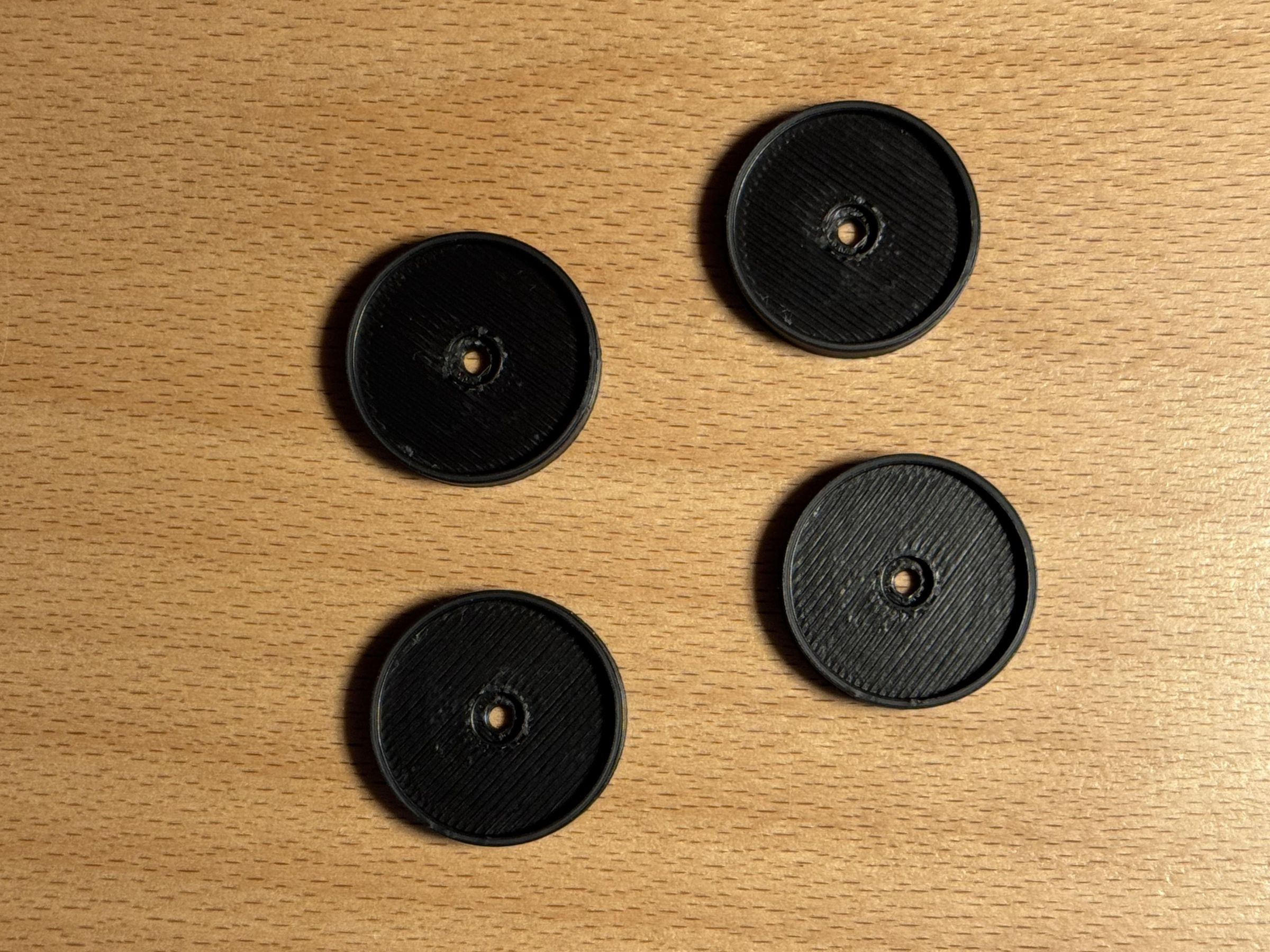
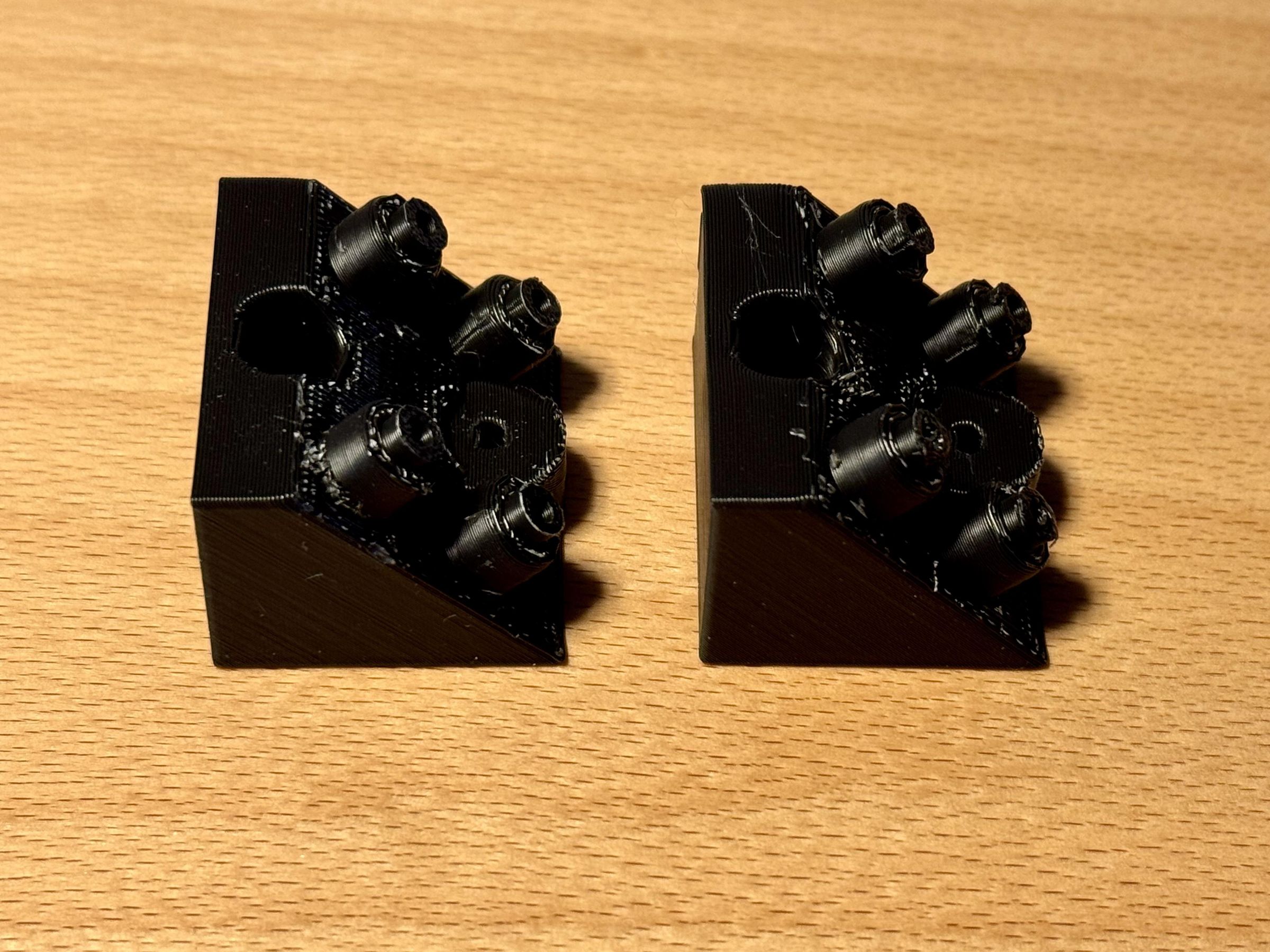
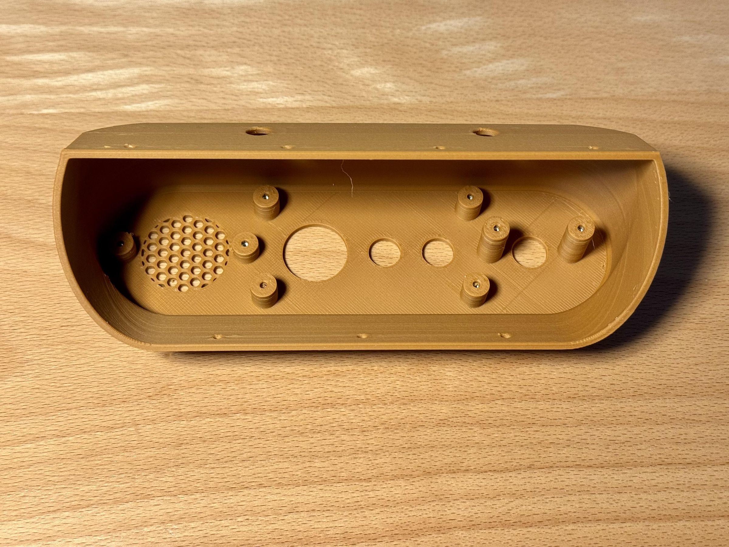
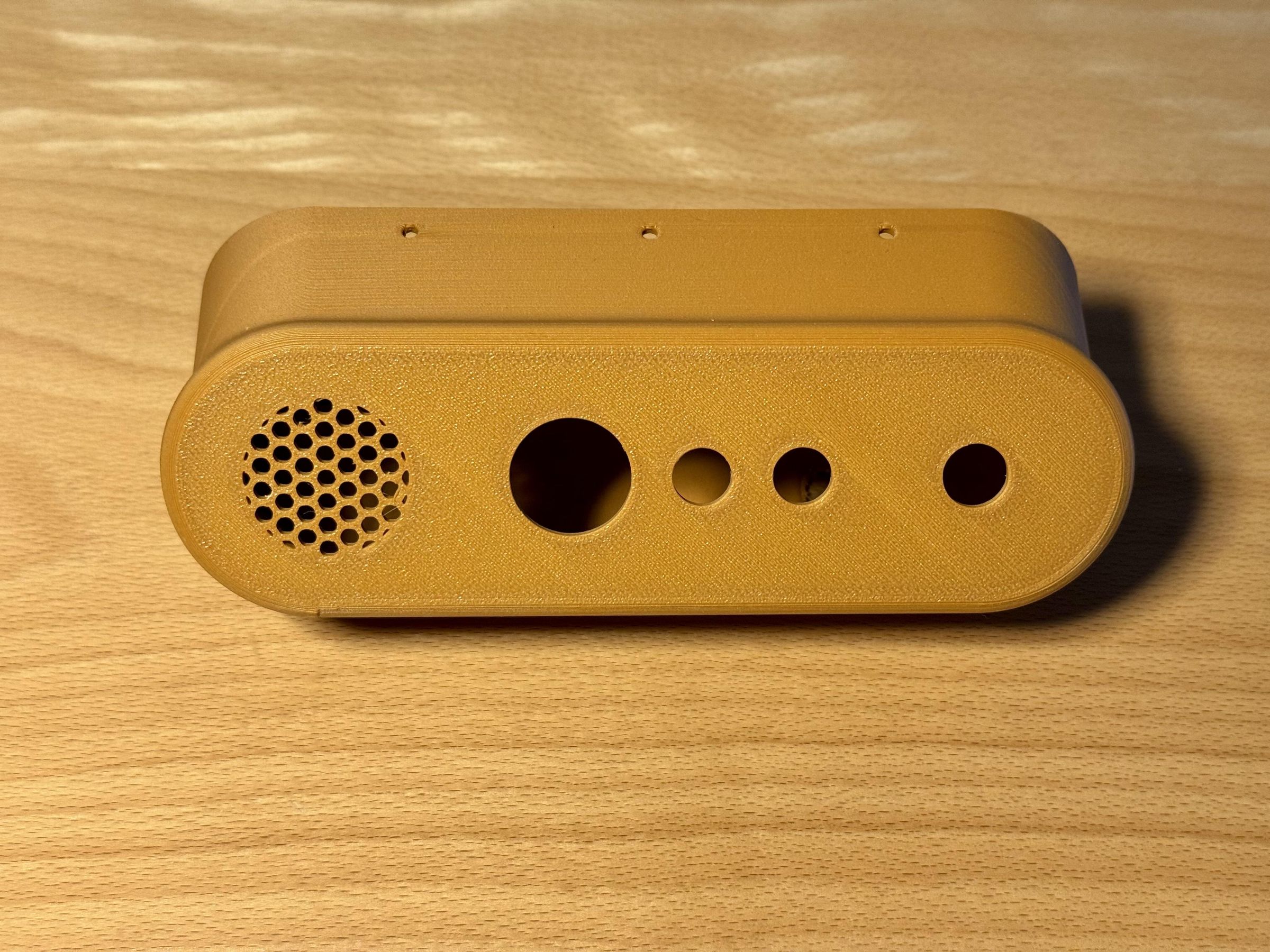
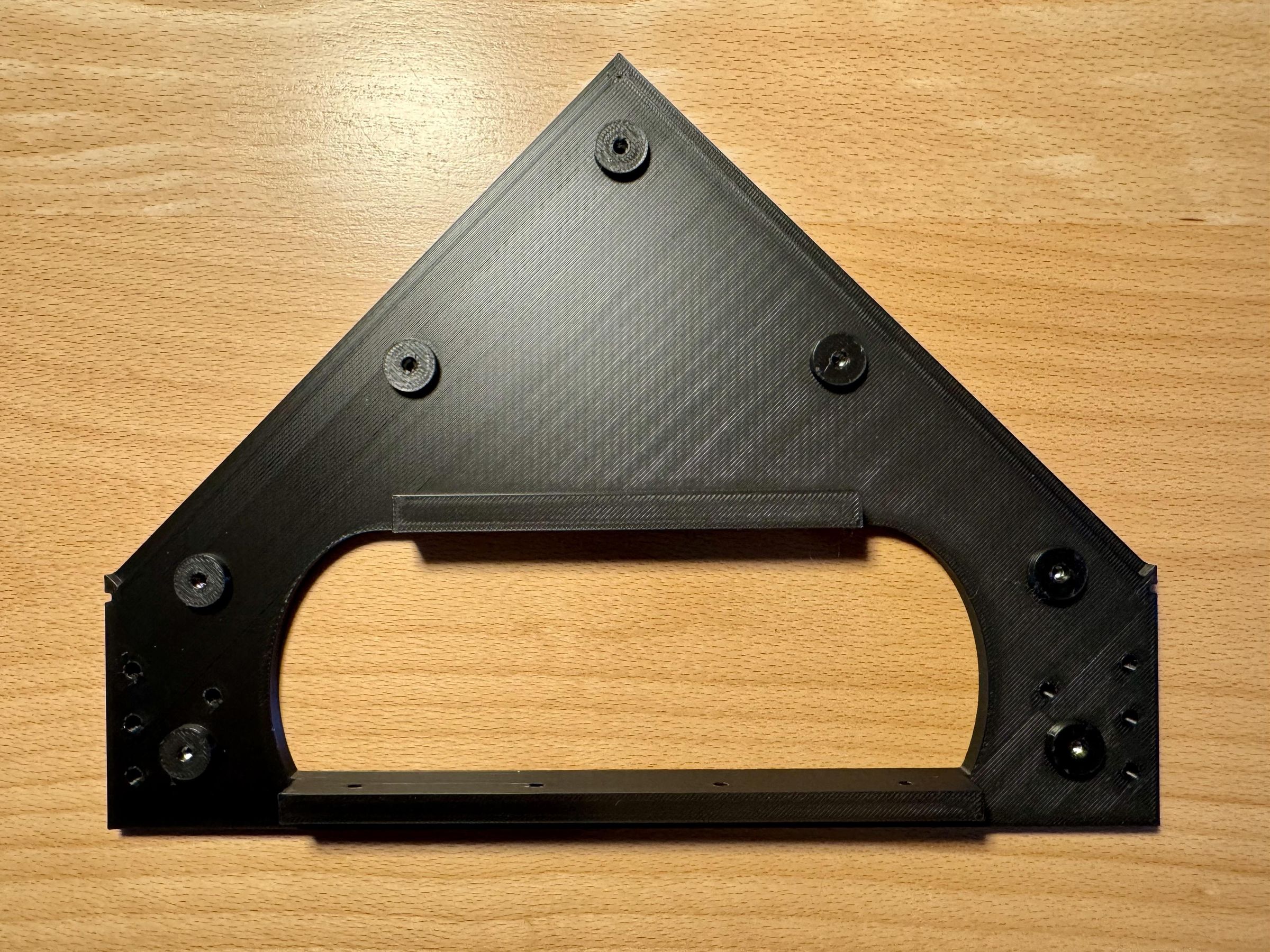
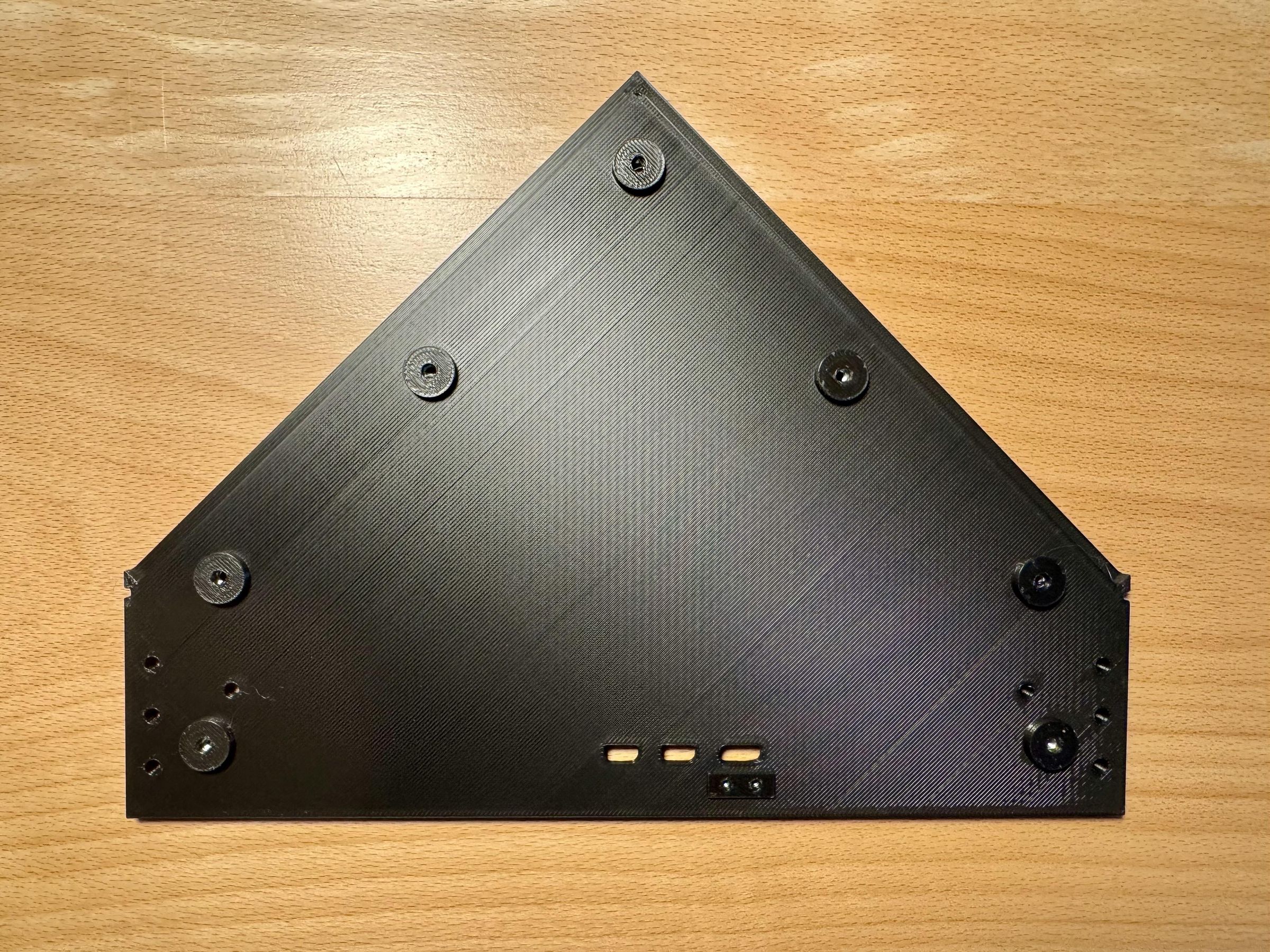
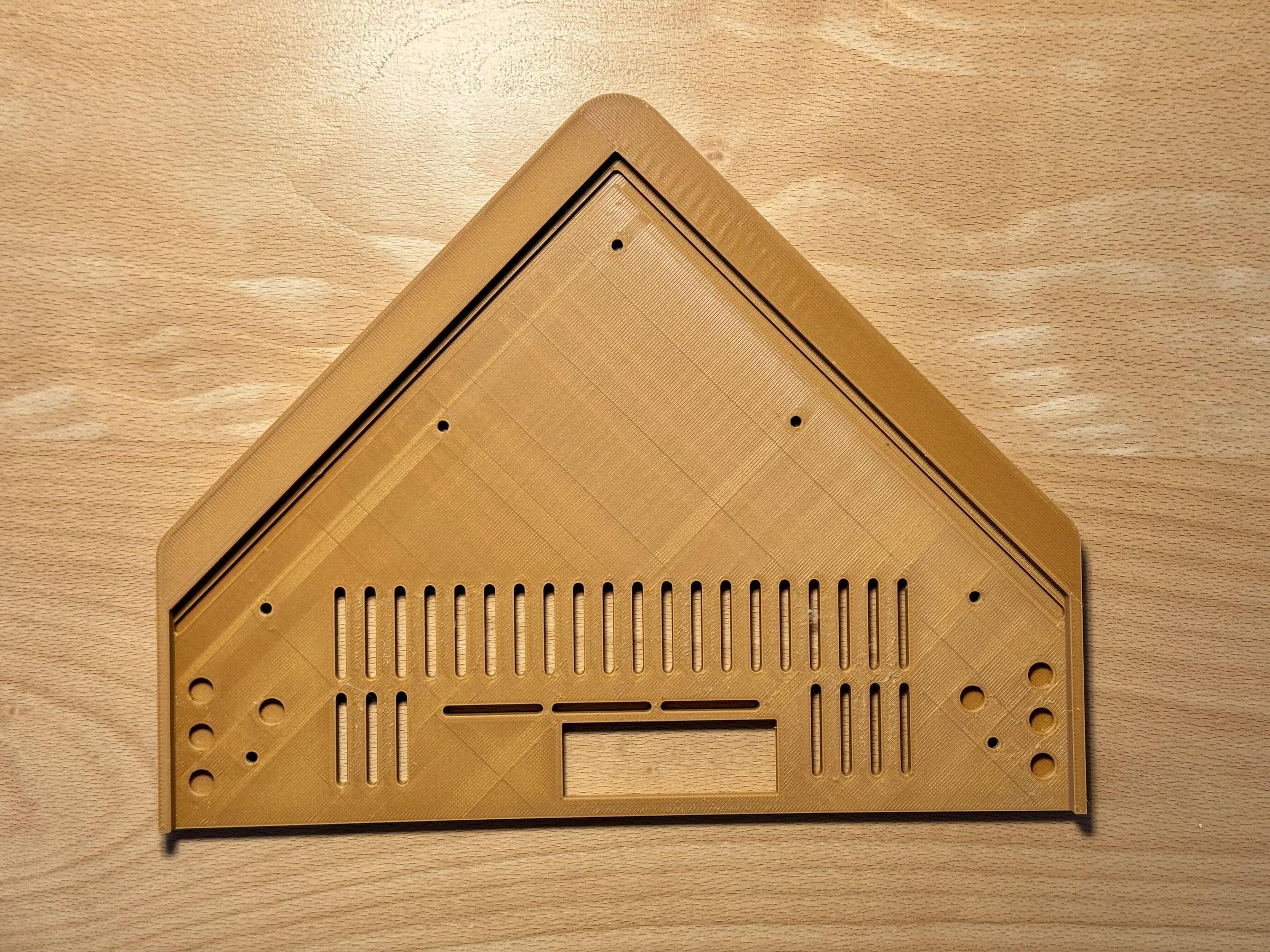
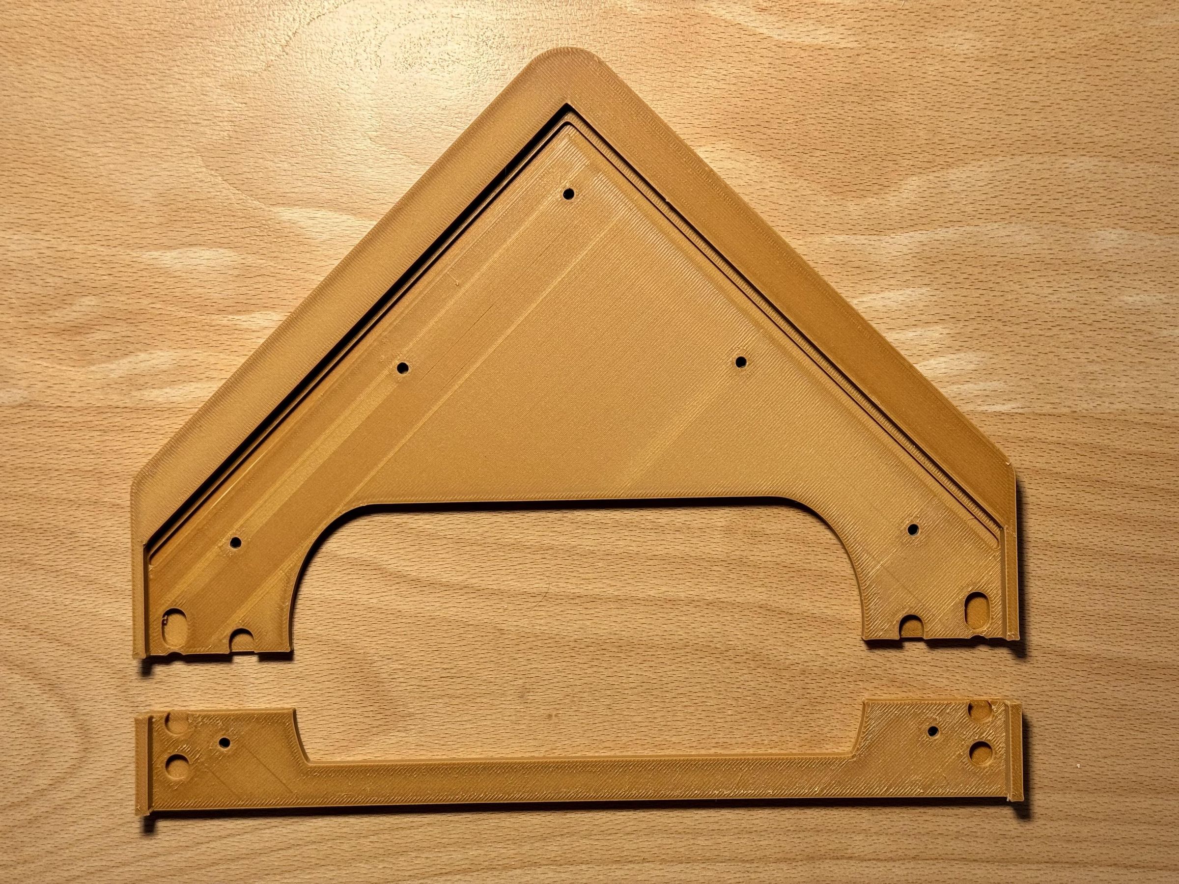
With the exception of the two glass panels, all mechanical enclosure parts are 3D-printed. I used a Bambu Lab X1C and printed all parts in PLA.
Some components are quite large and use almost the entire build volume of the printer. The base plate has therefore been divided into two sections, as it would otherwise be too large to print as a single part.
Allow the parts to cool sufficiently before removing them from the build plate, especially the large and thin components. Removing them while they are still warm can cause them to bend or warp as they continue to cool.
The GitHub repository contains all the files required for printing:
- The original Autodesk Fusion design files
- Exported STL files
- Ready-to-use Bambu Lab 3MF files
Selecting the Correct Parts for the Glass Panels
I ordered the two glass panels from an eBay seller who cut them to size. However, the short side of each panel was approximately 1 mm longer than specified.
For this reason, the parts named front, front2, back and back2 are provided in two versions. The files with the suffix _dev are designed for the slightly larger glass panels that I received.
Measure your glass panels carefully before printing these four parts and select the version that matches their actual dimensions.
Embedded Nuts and Screw Connections
The printed parts are joined to one another and to the electronic components using M2 and M3 screws. Please note that the Raspberry Pi 5 is mounted using M2.5 screws, so this additional screw size is required at this point. The models contain recesses into which the corresponding M2, M2.5, or M3 nuts are inserted during printing. The printer must pause at the correct layers so that the nuts can be placed into these recesses before printing continues.
The required pauses are already included in the supplied 3MF files. If you use a different printer or prepare the files with another slicer, you will need to add these pauses manually.
I have found this assembly method to be inexpensive, strong and very reliable.
Assemble the Enclosure and Install the Glass Panels
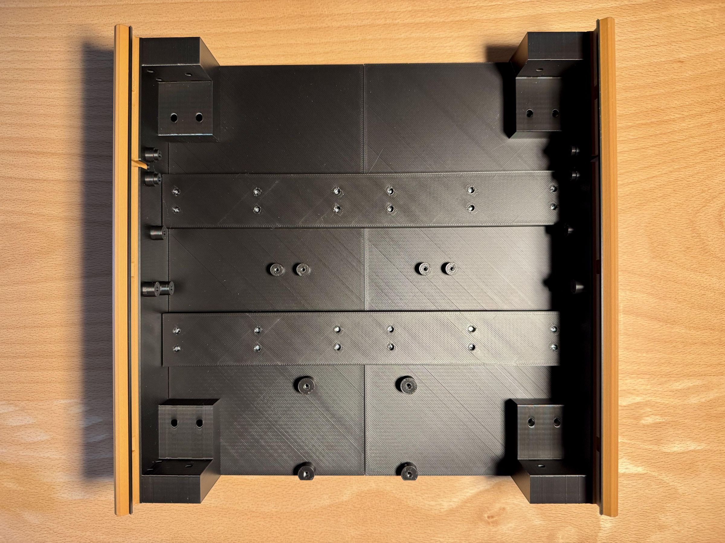
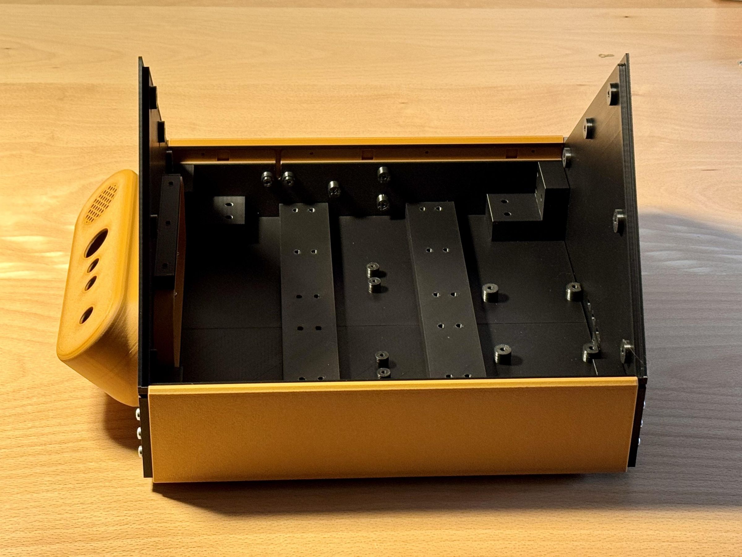
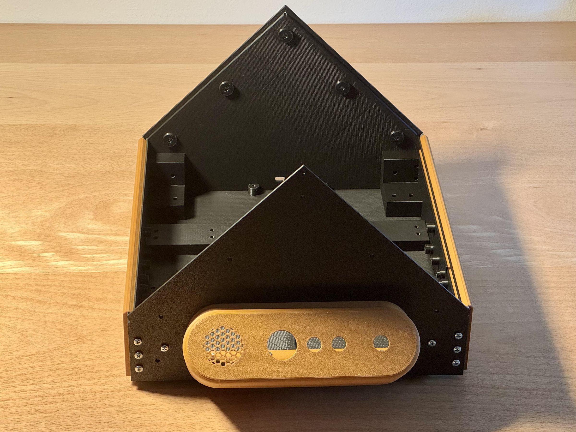
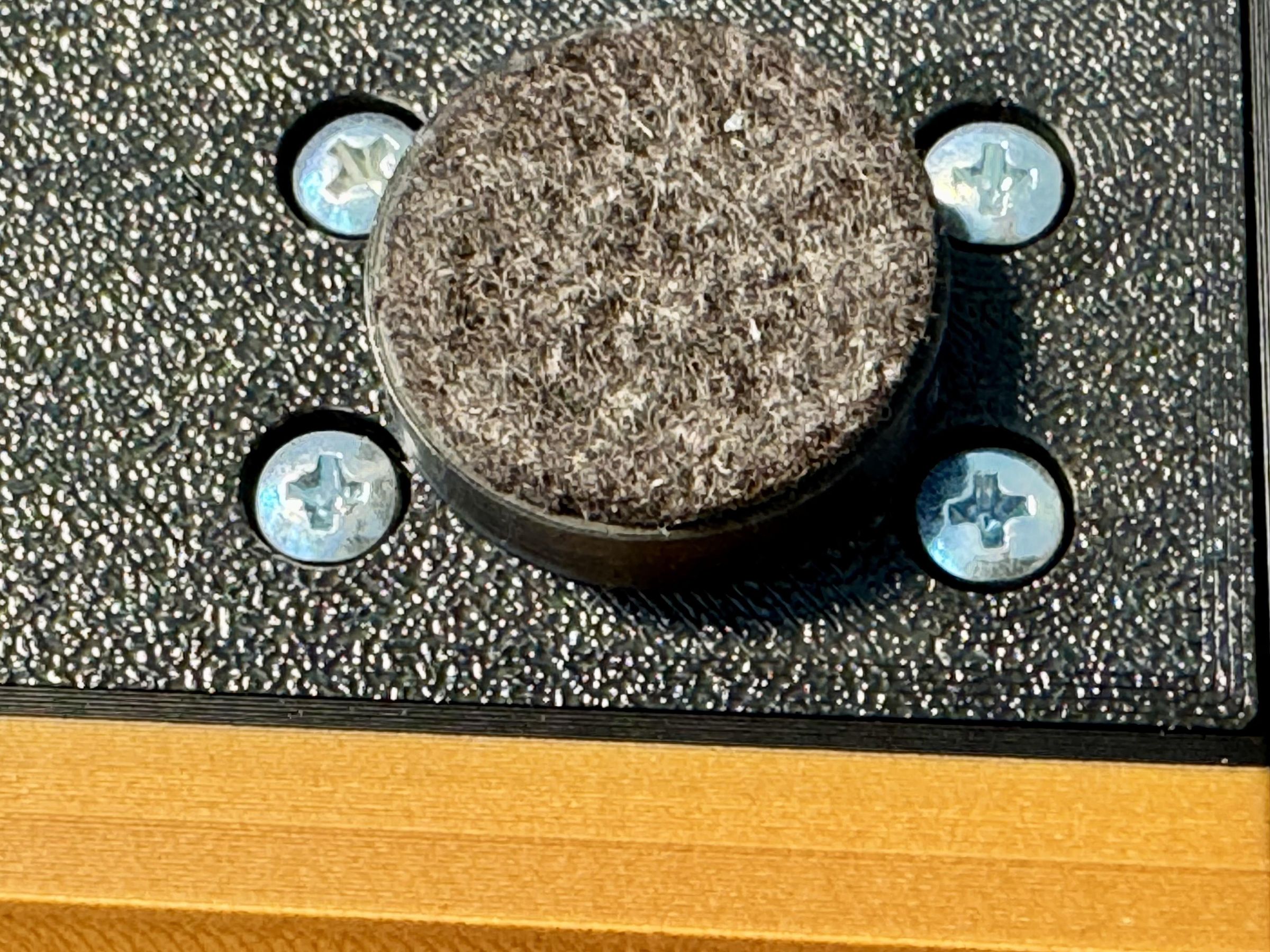
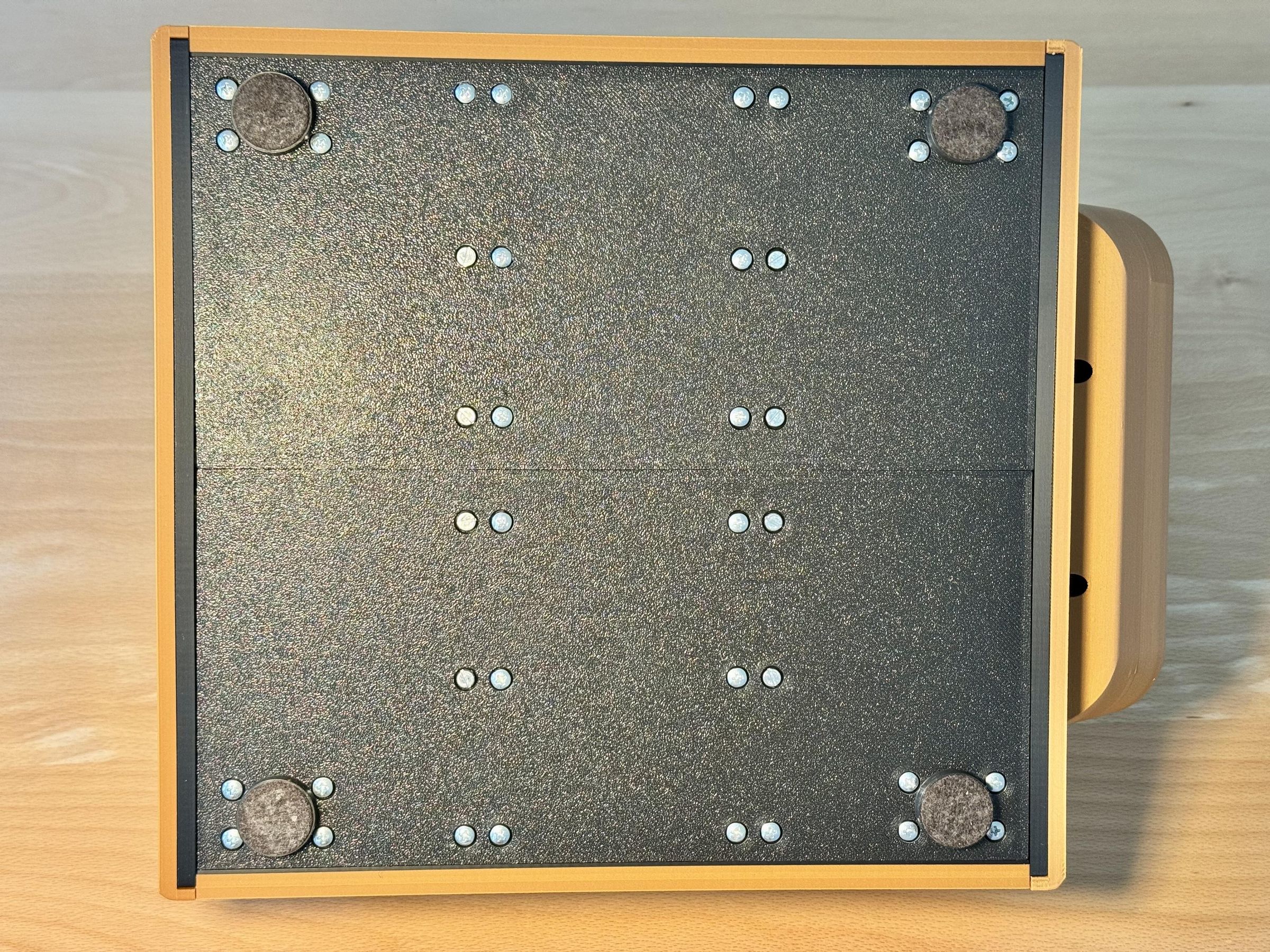
Join the printed enclosure parts using M2 and M3 screws. If the position or orientation of a component is unclear, refer to the complete Fusion assembly. The file abr.f3z is included in the GitHub repository and can be opened with Autodesk Fusion.
Each gable-shaped end of the enclosure consists of two parts:
- front and front2
- back and back2
The inner parts, front and back, are printed in black. First attach these parts to the remaining enclosure structure.
The two glass panels are then lowered from above into the corresponding recesses. The outer parts, front2 and back2, are printed in the wood-colored filament. Their edges overlap the glass panels and hold them securely in place.
Keep the Glass Panels Removable During Assembly
I recommend leaving front2 and back2 off while installing the electronics. Without these outer parts, the glass panels can be removed easily whenever access to the inside of the enclosure is required. They can also be reinserted quickly when needed for testing or camera adjustment.
Install front2 and back2 only after the remaining assembly and testing work has been completed. Until these parts are fitted, the glass panels are not secured and may slide out. Handle and move the enclosure accordingly.
Build the Control Panel
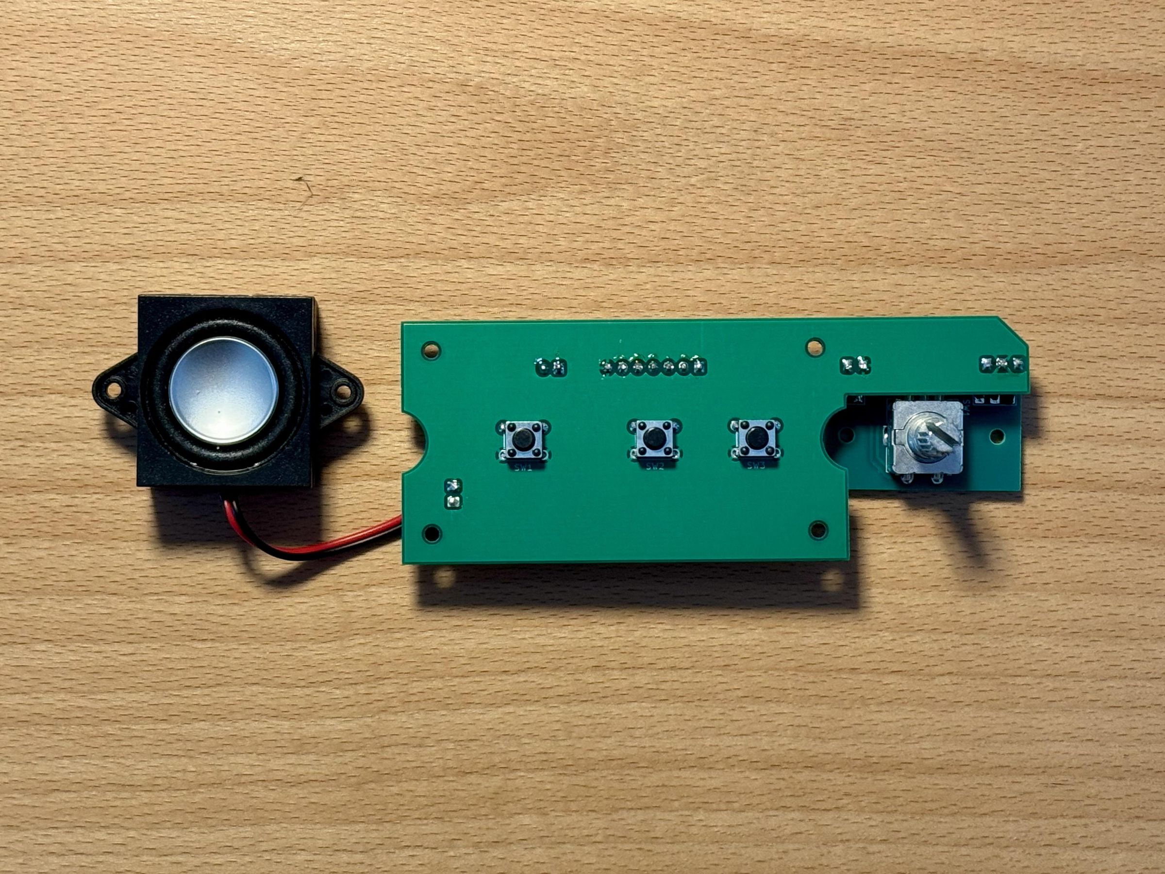
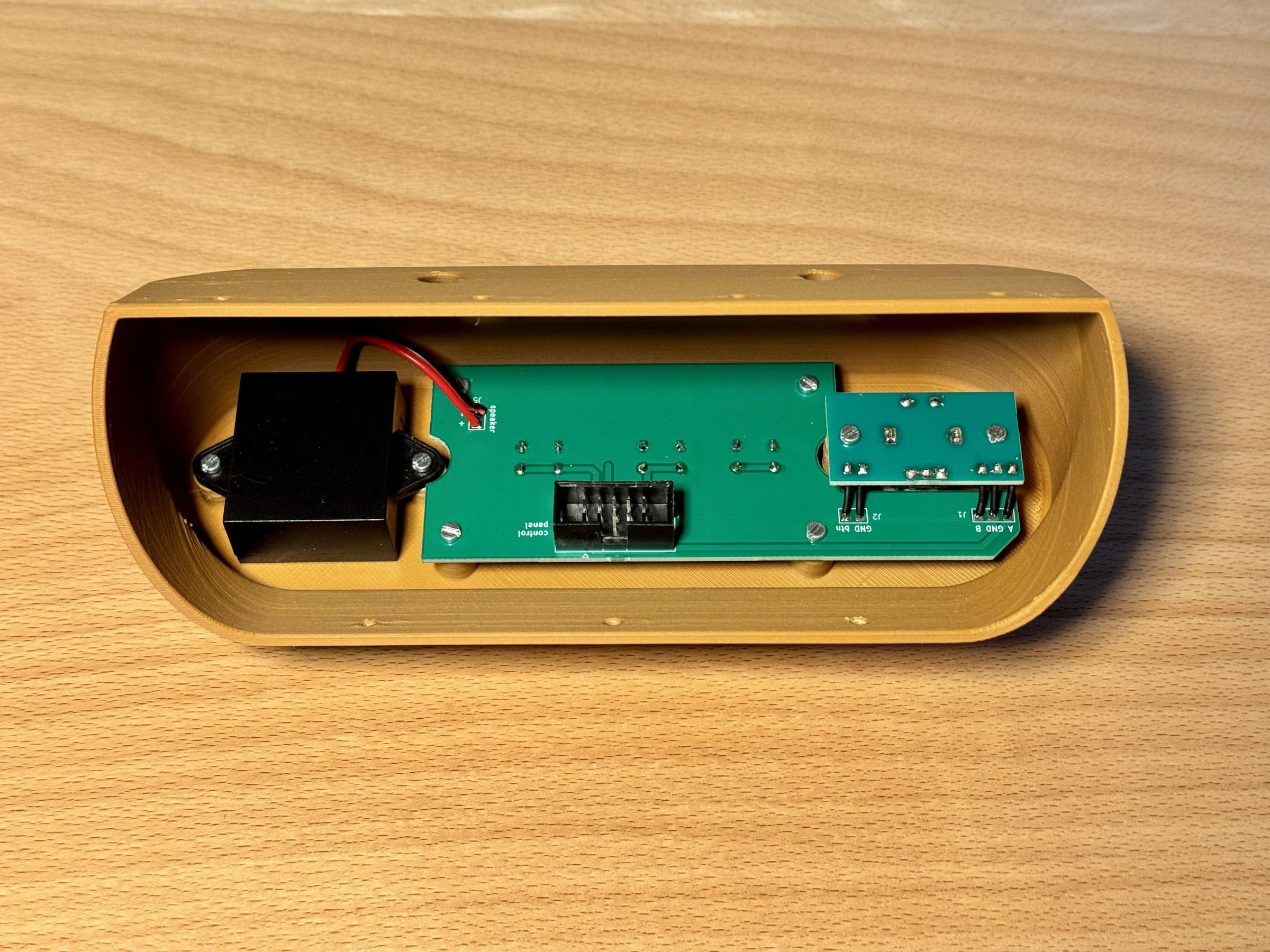
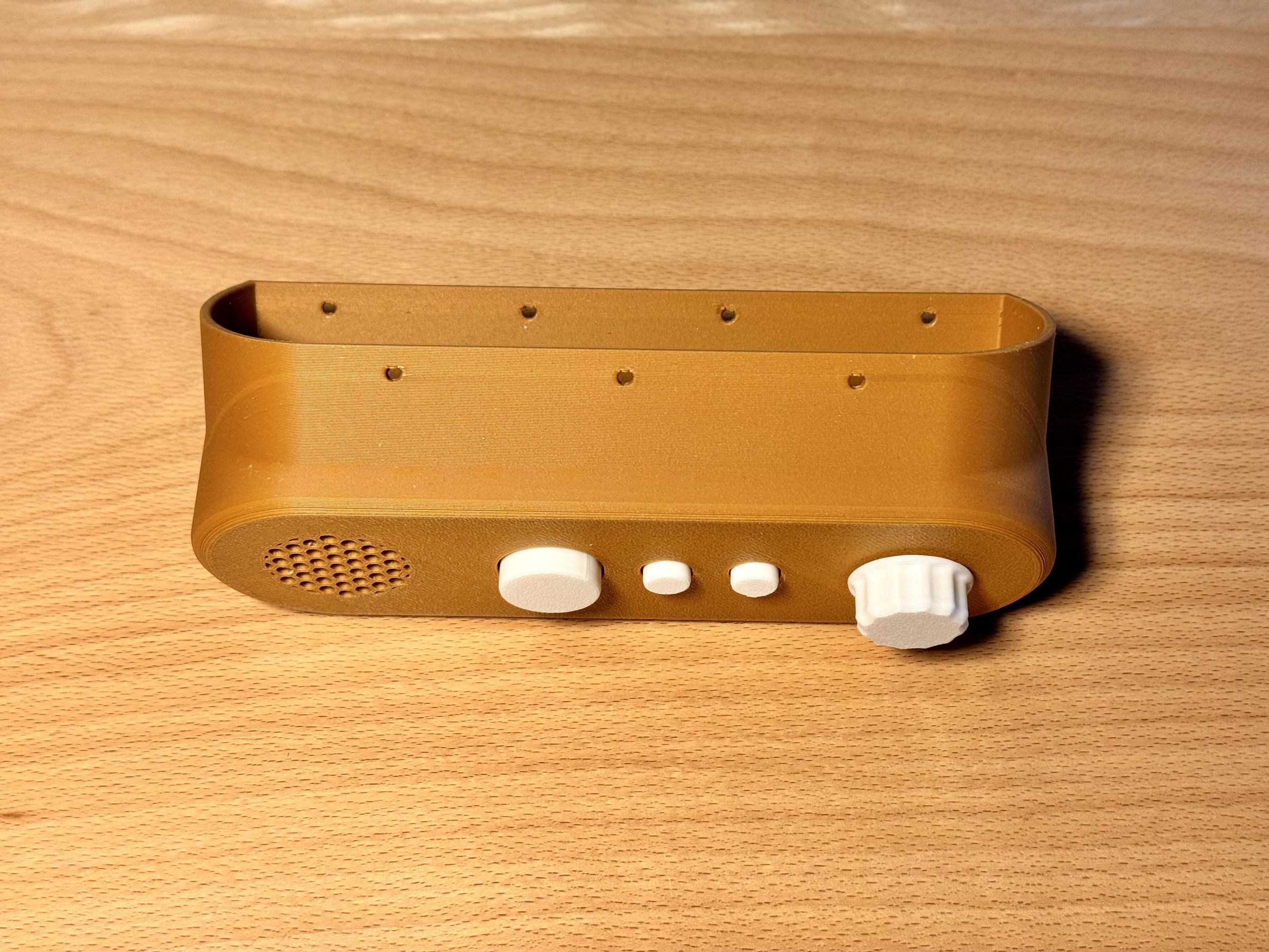
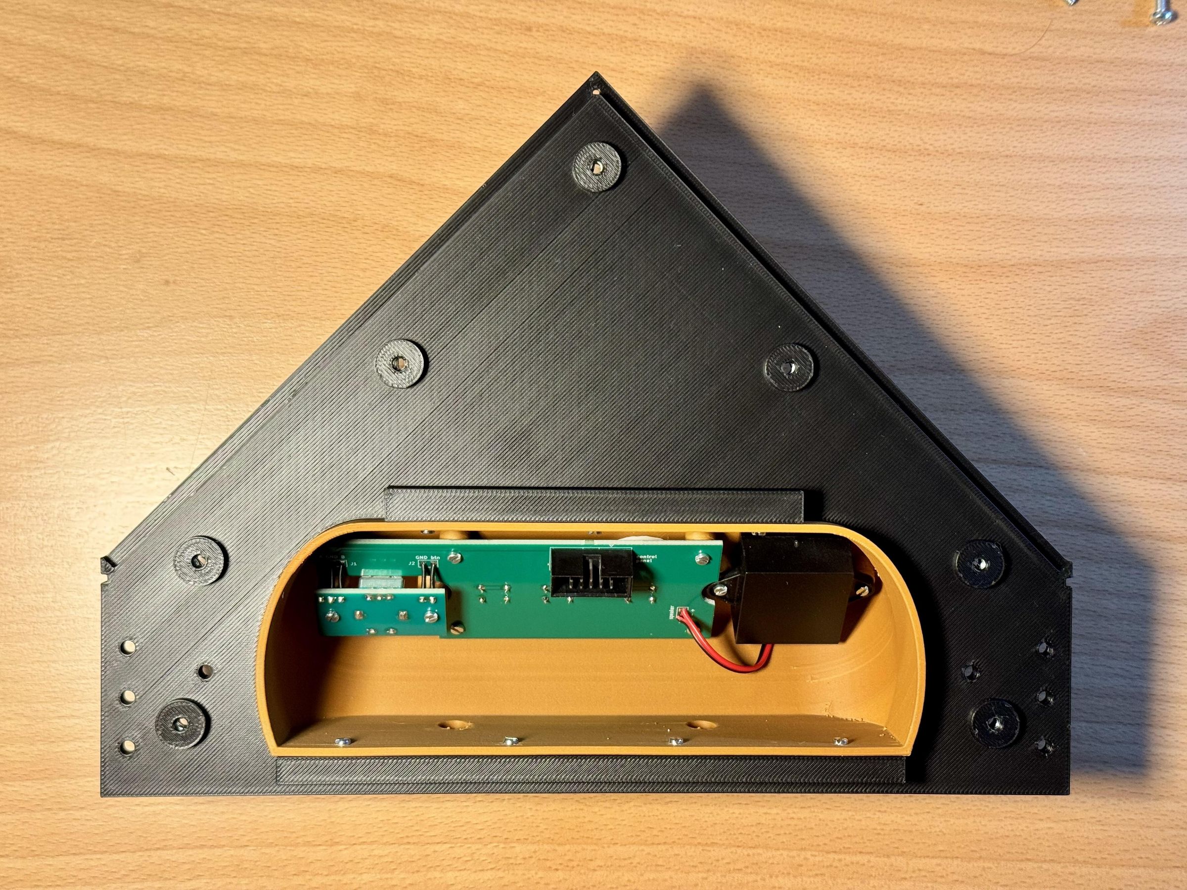
The control panel uses two custom PCBs. Begin by assembling and soldering both boards.
The larger PCB carries the three push buttons and the 10-pin connector used to connect the control panel to the Raspberry Pi. The smaller PCB carries the EC11 rotary encoder, which is used to adjust the volume.
Connect the EC11 board to the main control-panel PCB using five wires. The speaker is also connected directly to the larger PCB.
Before installing the electronics, inspect all solder joints and check the orientation of the connectors and components. Once the soldering and wiring are complete, mount both PCBs and the speaker inside the printed control-panel enclosure. Make sure that the buttons and rotary encoder move freely through their corresponding openings before securing the assembly.
Install the Raspberry Pi 5
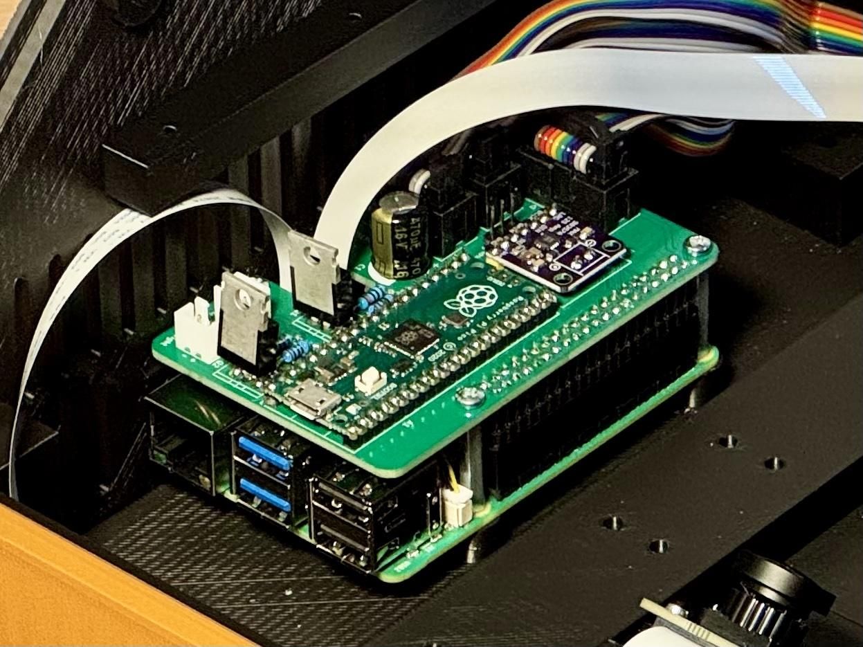
First, install the official Raspberry Pi Active Cooler for Raspberry Pi 5. Follow the installation instructions provided in the Raspberry Pi 5 documentation.
Active cooling is necessary because the Raspberry Pi operates at a high processing load while performing OCR on the captured page images. The ventilation openings in the enclosure allow the cooler to exchange air with the outside.
After fitting the cooler, mount the Raspberry Pi 5 on the base plate using four M2.5 × 20 mm standoffs. Check that the board is correctly oriented and that its connectors and ventilation openings remain accessible before tightening the fasteners.
Install the Camera Cables
Before installing the extension board in the next step, insert the two 22-pin, 200 mm FFC cables into the camera connectors on the Raspberry Pi. These connectors will no longer be accessible once the extension board has been fitted.
The locking parts of the connectors are fragile, so open them and insert the cables very carefully to avoid damaging the plastic components.
Use Type B FFC cables. On this cable type, the exposed contacts are located on the upper side at one end and on the lower side at the other end.
Assemble the Expansion Board
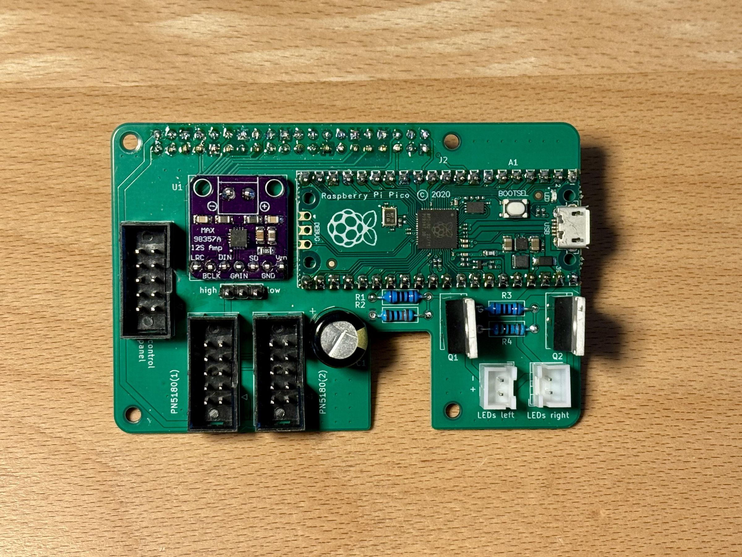
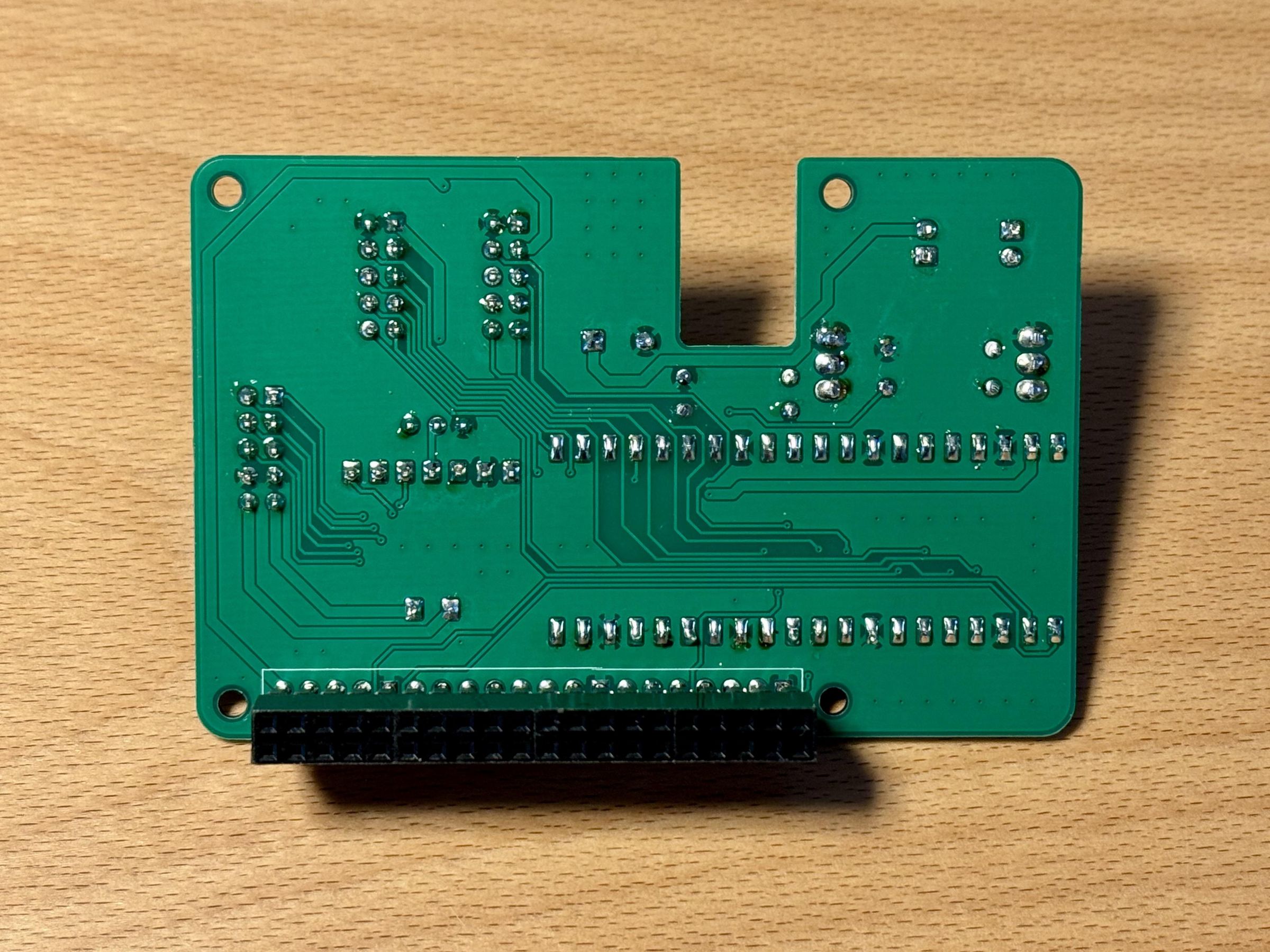
The expansion board connects the Raspberry Pi 5 to the main peripheral assemblies:
- The control panel
- Two PN5180 NFC readers
- Two LED PCBs
These connections are provided by three 10-pin IDC headers and two 2-pin JST-XH connectors with a 2.5 mm pitch.
The board also carries a MAX98357A breakout board for audio output and a Raspberry Pi Pico, which handles communication with the two PN5180 NFC readers. Each LED board is switched by a high-power N-channel MOSFET.
Solder the components onto the expansion board as shown in the photograph. Pay particular attention to the orientation of the connectors, the Raspberry Pi Pico, the MAX98357A module, the MOSFETs and all polarized components. The complete schematic and PCB layout are available in the KiCad design files in the GitHub repository.
After checking the solder joints, carefully align the expansion board with the Raspberry Pi 5 GPIO/HAT header and press it into place. Make sure that all header pins are correctly aligned and that the previously installed camera cables are not trapped or damaged.
Finally, secure the expansion board to the M2.5 standoffs using M2.5 screws.
Install the NFC Antennas
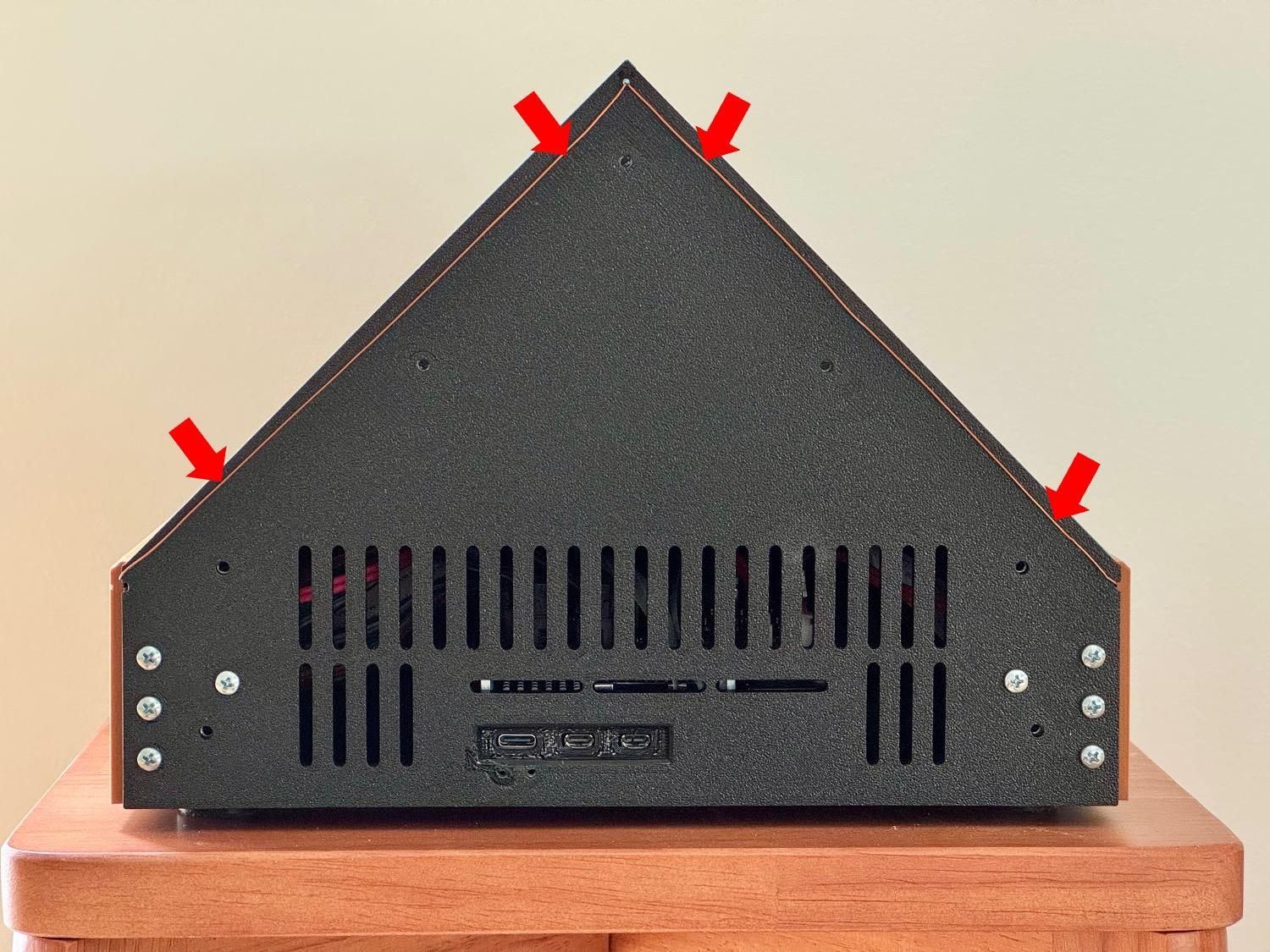
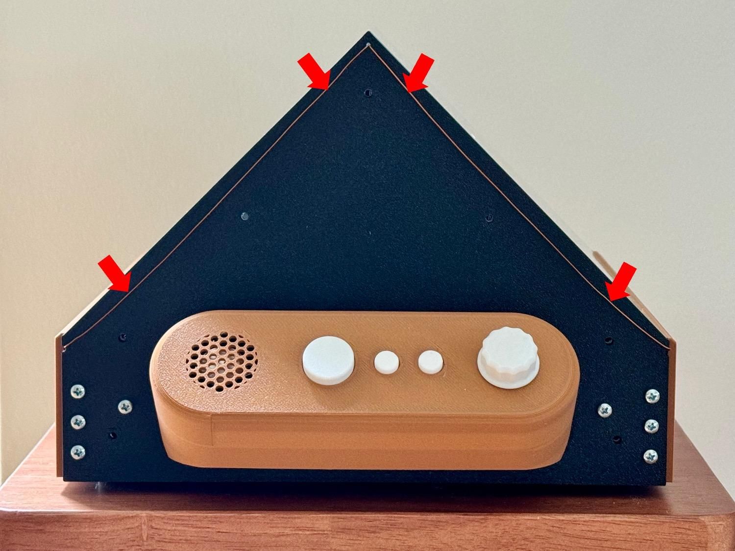
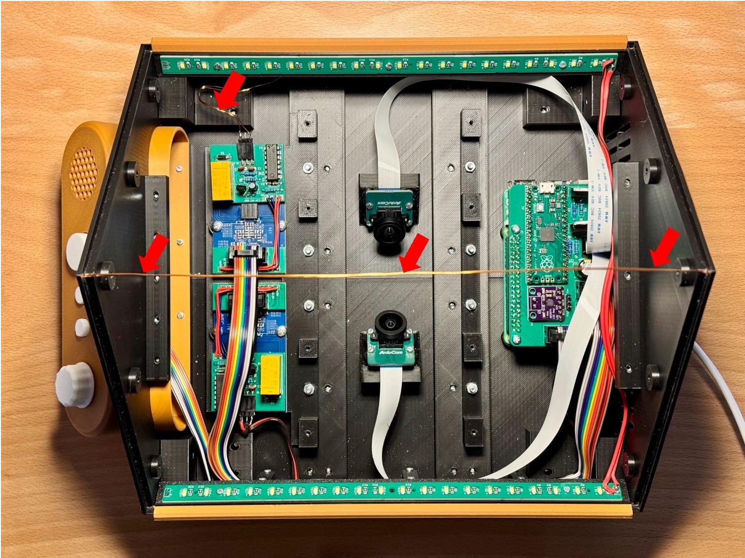
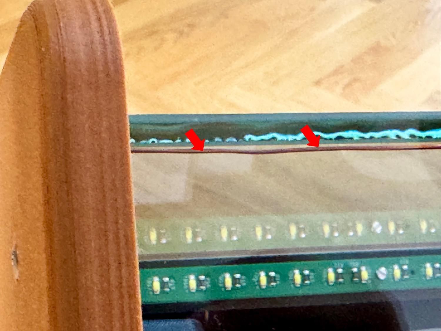
The device uses two NFC antennas so that tags can be detected on either side of the book. Each antenna consists of a single-turn coil made from 0.5 mm diameter enamelled copper wire and runs around one of the two glass panels.
Small openings are provided in the front and back enclosure parts for routing the antenna wire. Along the short sides of each glass panel, guide the wire across the surfaces of these two parts, as shown in the photographs.
Along the upper long edge, the wire runs freely from the front to the back of the enclosure. In the assembled device, this section is visible in the angle between the two glass panels.
Along the lower long edge, route the wire behind the triangular mounting rail for the LED PCB. Keep the wire close to the intended path.
Repeat the process for the second glass panel to create two separate single-turn antennas. Leave sufficient wire at both ends for connection to the corresponding PN5180 reader in a later step.
Install the LED Boards
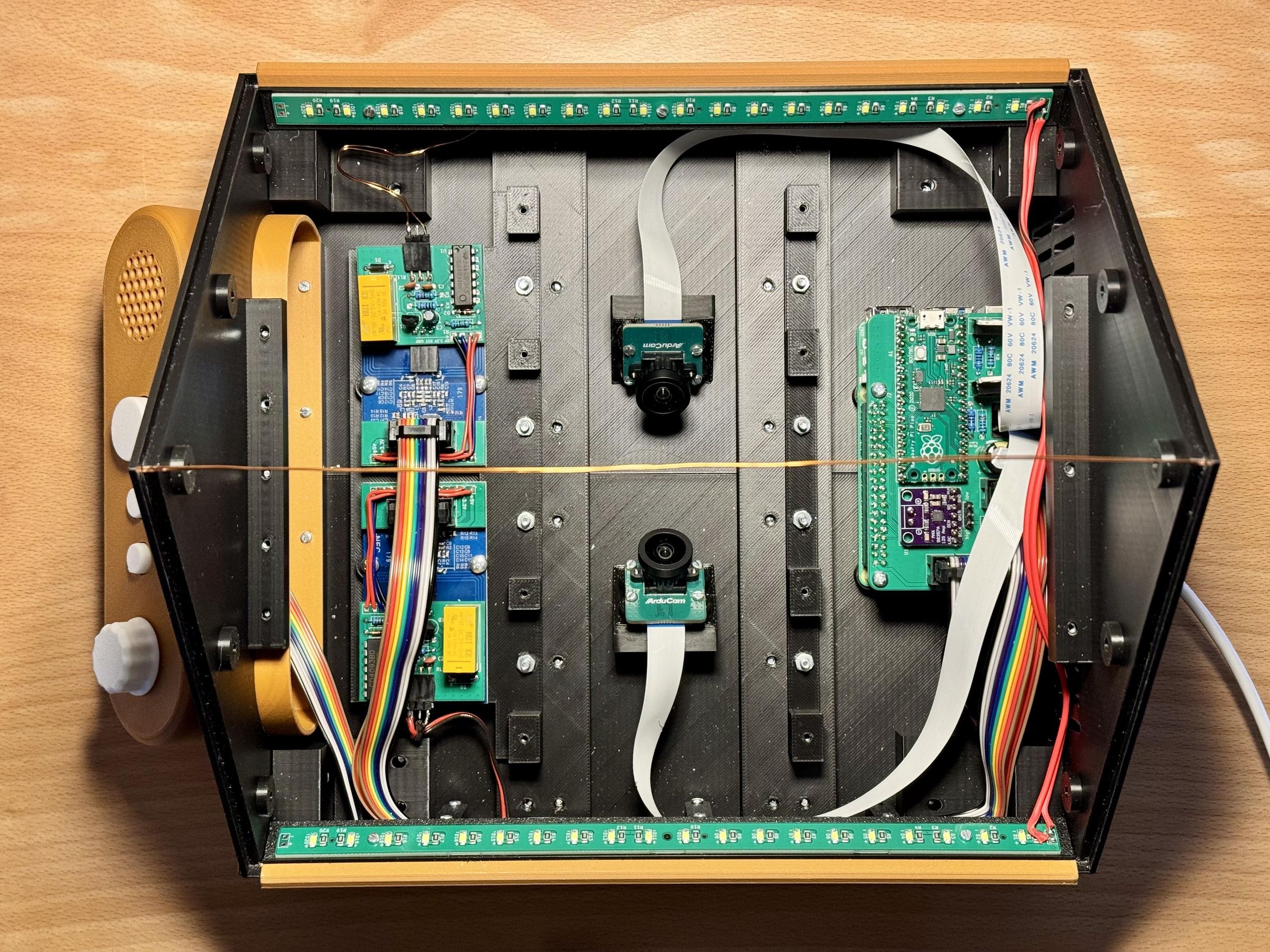
Begin by connecting a short two-core cable to each LED PCB. Terminate the other end of each cable with a crimped 2-pin JST-XH connector. Observe the polarity indicated on the LED boards and the expansion board.
Next, attach the left and right triangular mounting rails to the corresponding enclosure parts using M2 screws.
These rails are positioned directly in front of the grooves carrying the NFC antenna wires. Before tightening the screws, make sure that each wire is seated completely inside its groove and is not trapped or pinched beneath a mounting rail.
Mount the two LED PCBs onto the triangular rails and secure them with M2 screws. Finally, connect their JST-XH plugs to the corresponding LEDs left and LEDs right sockets on the Raspberry Pi expansion board.
Modify the PN5180 Breakout Boards
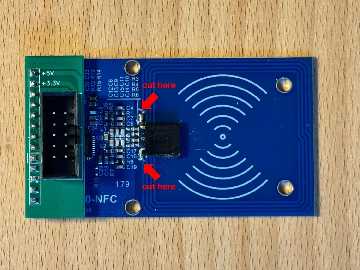
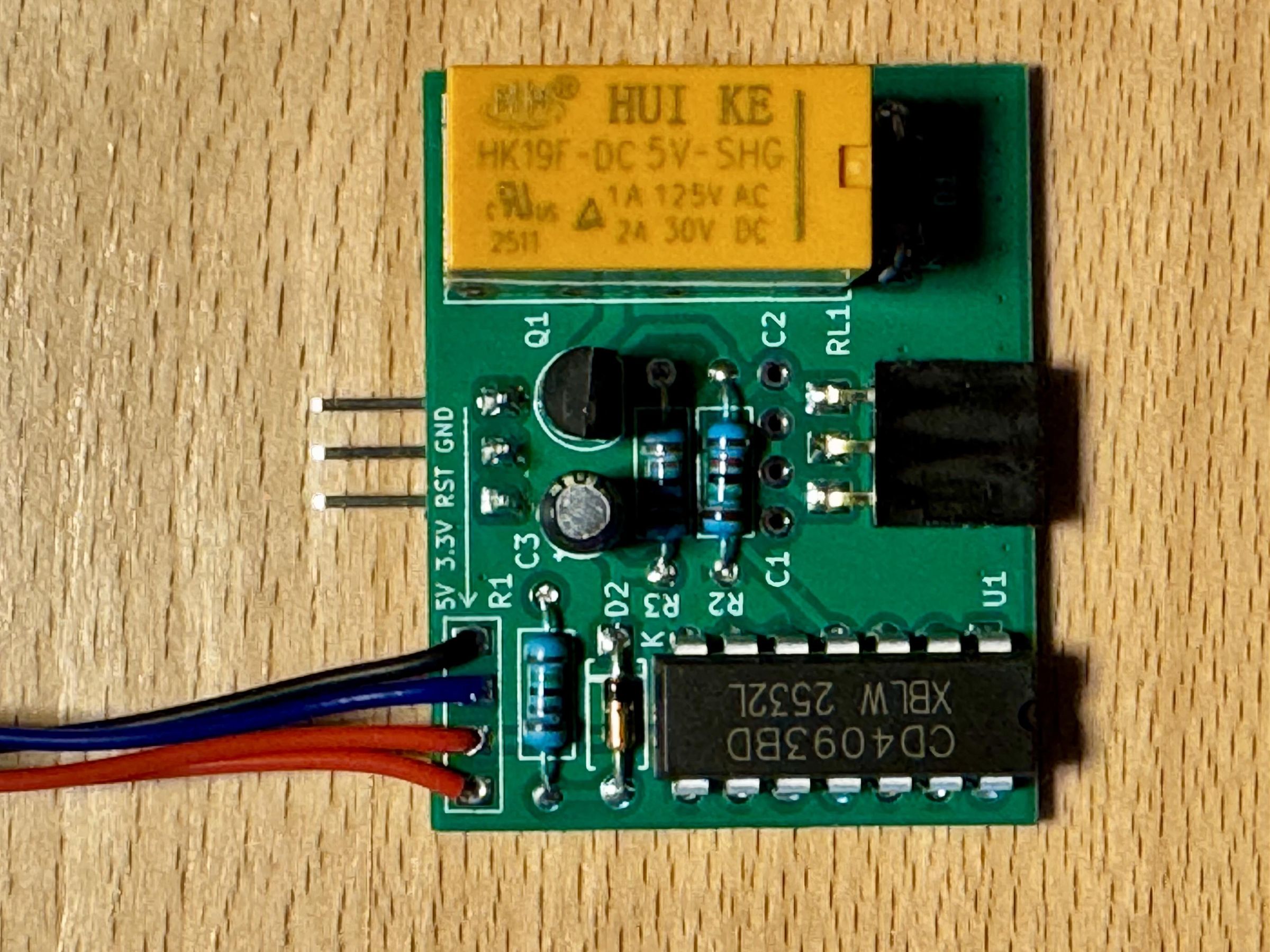
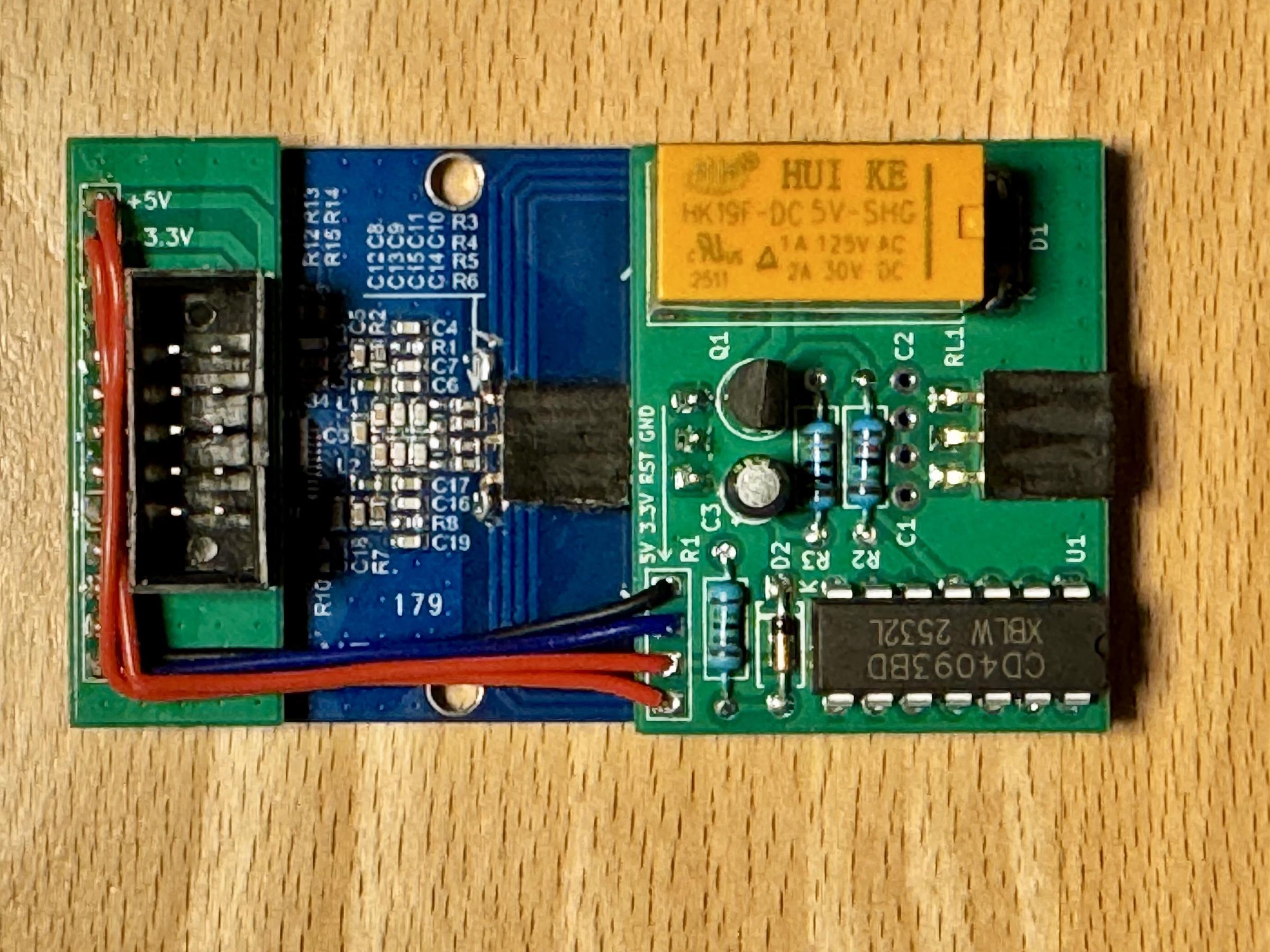
The NFC system is based on two PN5180 breakout boards. Each module includes a printed onboard antenna, but its reading range is insufficient for the Accessible Book Reader. The boards must therefore be modified to accept the large external antenna loops installed around the glass panels.
This modification is irreversible, so inspect the photographs carefully before cutting any traces.
First, interrupt the PCB trace of the printed antenna at both ends. The exact locations of the two cuts are shown in the photographs. Make sure that each trace is cut completely and verify that the onboard antenna is electrically disconnected.
Next, carefully remove a small area of solder mask from each antenna connection point to expose the copper underneath. Tin the exposed copper and solder the antenna connector onto the two prepared contact points, as shown in the photographs. Avoid applying heat for too long, as this could lift the copper traces from the PCB.
Switching Between the Two Antennas
The two PN5180 readers cannot operate simultaneously because their antennas would interfere with one another. Even an inactive second antenna can affect the reader currently in use if it remains electrically connected.
For this reason, a small relay interface board was developed and inserted between the PN5180 readers and their external antennas. When one reader is active, the relay circuit electrically disconnects the antenna associated with the other reader. The system then switches over when the opposite side of the book needs to be checked.
This arrangement prevents the two large antenna loops from interfering with each other and has proved very reliable in practice.
Assemble the Relay Board
Solder the relay, the CD4093 logic IC and the remaining components onto the relay board. Then connect the relay board to the PN5180 breakout board using four wires. Refer to the photographs and the KiCad design files in the GitHub repository for the component placement, wiring details and connection points.
Select the Antenna Tuning Capacitors
Capacitors C1 and C2 are used to tune the antenna’s resonant frequency to the operating frequency of the NFC reader. The two capacitors are connected in parallel, so their capacitances are added together.
If you intend to use only ISO 15693 tags, fit a 22 pF capacitor in one position and leave the other position unpopulated. If you also want to use ISO 14443A tags, a more precise antenna-tuning procedure is recommended and is described in a later step.
To prepare for this adjustment, initially install an 18 pF capacitor. During the tuning process, small additional capacitances of 2 pF, 3 pF, 4 pF or 5 pF can then be added to obtain the best result.
Install the Interface Adapter
The connection to the Raspberry Pi Pico is provided by a small interface board fitted with a 10-pin IDC connector. First, solder the IDC connector onto the interface board. Then use a pin header to solder the completed interface board to the PN5180 breakout board. Check the orientation of both the IDC connector and the pin header before soldering.
Install the Cameras
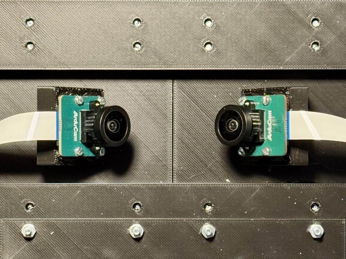
Before mounting the two camera modules, release the focus adjustment on each lens. The lens ring is secured with a small amount of adhesive, which must be cut carefully with a sharp knife.
Inspect the adhesive joint with a magnifying glass while working. Cut only through the adhesive and take particular care not to damage the fine lens thread or nearby camera components. Once the adhesive has been released, the lens can be rotated and the camera can be focused manually during commissioning.
Next, attach the two camera mounts to the base plate using M2 screws. Install each camera module in its holder with four screws. The holders position the cameras at the required 45-degree angle.
Finally, connect the previously installed FFC cables to the camera modules. The FFC connectors and their locking tabs are fragile, so insert the cables straight and close the locks carefully. Make sure that each cable is fully seated and correctly oriented before securing the cameras and routing the cables.
Connect the Electronics
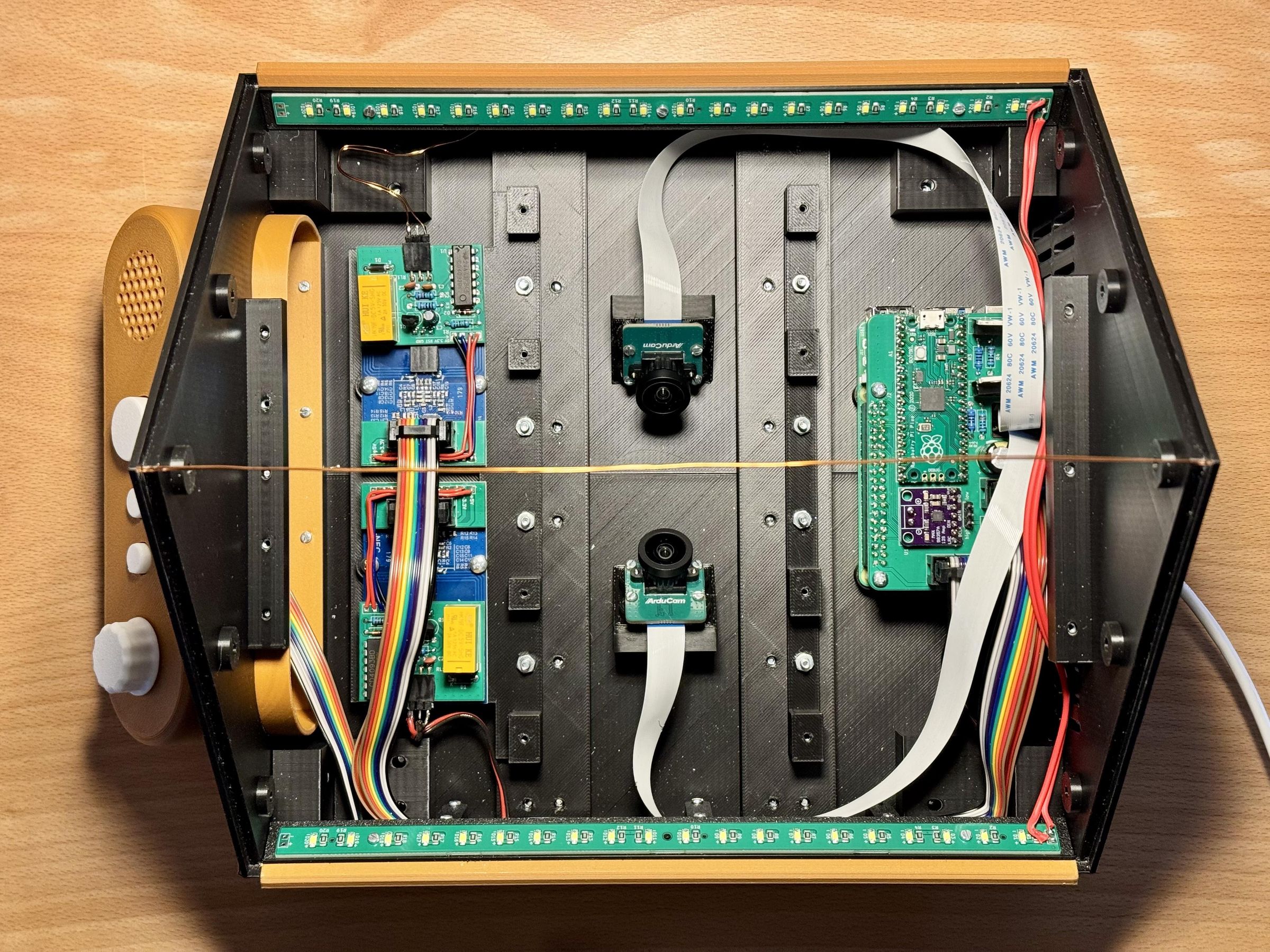
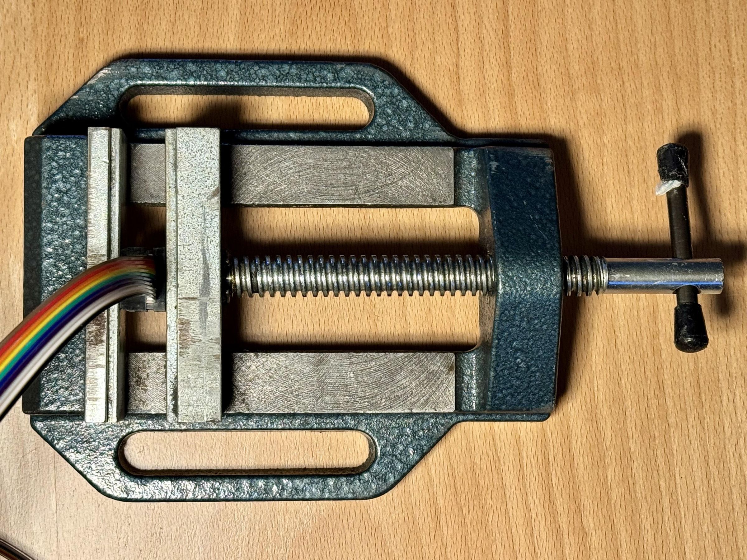
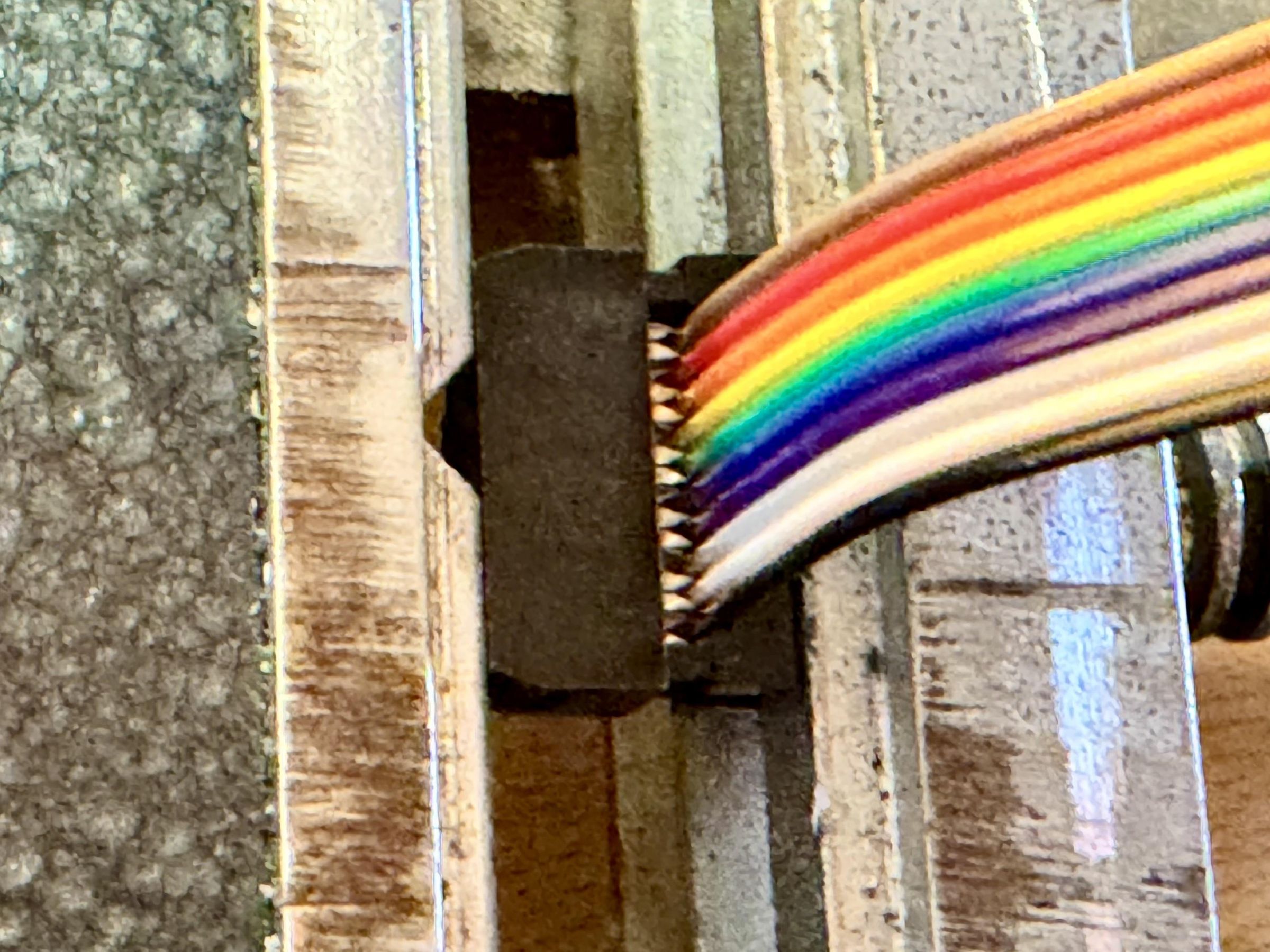
Three 10-conductor ribbon cables are used to connect the Raspberry Pi expansion board to the control panel and the two PN5180 assemblies.
Attach a 10-pin IDC connector to each end of every ribbon cable. An easy way to press the connectors onto the cable is to use a bench vise, as shown in the photograph. Align the connector carefully and close the vise slowly so that pressure is applied evenly across its entire width.
Pay attention to the pin 1 orientation when fitting the connectors. The marked conductor on the ribbon cable, usually indicated by a colored stripe, should correspond to pin 1 at both ends. Also check the orientation of the connector’s key and strain-relief section before pressing it together.
Once all six connectors have been installed, inspect the cables and verify their continuity if possible. Then connect one cable to the control panel and one to each PN5180 assembly. Plug the opposite ends into the corresponding connectors on the Raspberry Pi expansion board.
Install the Firmware on the Raspberry Pi Pico
The firmware can be installed on the Raspberry Pi Pico by copying a UF2 file to its USB bootloader drive. No additional programming hardware is required.
The prepared firmware image is located in the repository at:
hardware/pn5180_gateway/firmware/pn5180_gateway_pico.uf2
Install it as follows:
- Disconnect the Raspberry Pi Pico from USB.
- Press and hold the BOOTSEL button on the Pico.
- While continuing to hold the button, connect the Pico to your computer using a USB cable.
- Release the BOOTSEL button.
- A removable drive named RPI-RP2 should appear on the computer.
- Drag the pn5180_gateway_pico.uf2 file onto the RPI-RP2 drive.
After the file has been copied, the drive will disappear automatically and the Pico will restart with the new firmware. This is normal and indicates that the firmware has been installed.
Install the Electronics Covers
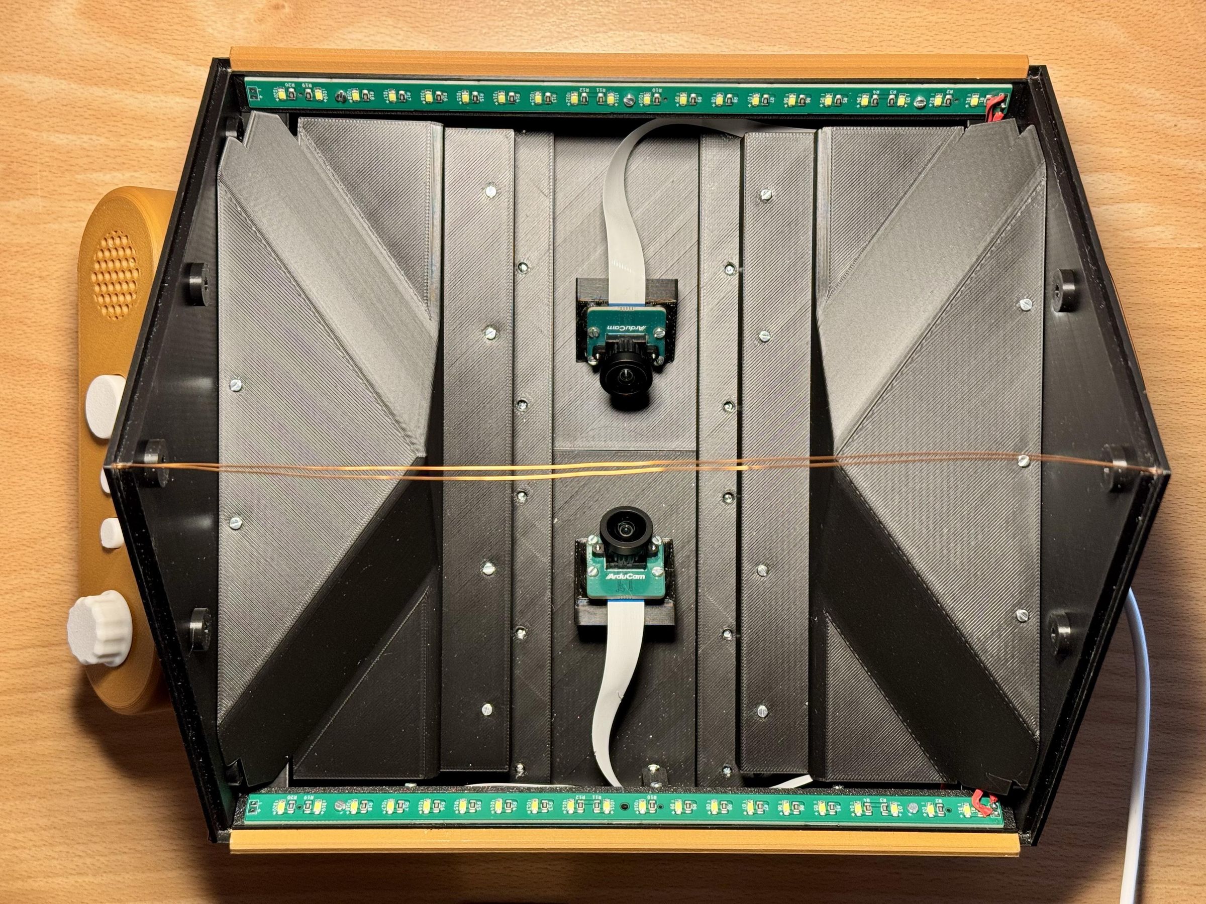
After all electronic components have been installed and the wiring is complete, fit the two internal electronics covers.
Before securing them, check that all connectors are fully inserted and that no cables are trapped between the covers and the enclosure. Route the cables through the intended openings.
The cover above the Raspberry Pi also forms a closed ventilation compartment. The ventilation slots connect this compartment to the outside of the enclosure, allowing the Raspberry Pi Active Cooler to circulate air between the enclosed volume and the surrounding environment.
Install and secure both covers only after confirming that the electronics and all cable connections are working correctly.
Set Up the Raspberry Pi 5
Installing and configuring the Raspberry Pi software involves several system and cloud-service settings. Since these instructions may change as the project develops, this step provides only an overview. Always follow the current documentation in the GitHub repository for the complete commands and verification procedures.
The main references are:
- Project README and installation overview
- Detailed Raspberry Pi setup guide
- Control-panel system service
- Language configuration
- PN5180 Pico gateway
Install the Operating System
Install Raspberry Pi OS Lite (64-bit) using Raspberry Pi Imager. During this process, create a user account, enable SSH and configure an initial network connection.
After the first boot, connect to the Raspberry Pi and update the operating system:
Install the required system packages using the package list provided in the Raspberry Pi setup guide.
Download the ABR Software
Clone the repository into the recommended directory:
Create a new Python virtual environment and install the ABR software and its main dependencies:
Do not copy a virtual environment from another computer. It must be created directly on the Raspberry Pi.
Configure the Hardware Interfaces
The Raspberry Pi boot configuration must be adjusted for:
- The two IMX519 cameras
- The UART connection to the Raspberry Pi Pico
- The I²S connection to the MAX98357A audio amplifier
The required settings are described in detail in docs/RASPBERRY_PI_SETUP.md. Use the repository’s config.txt only as a reference and do not replace the existing /boot/firmware/config.txt file without reviewing its contents.
The MAX98357A must also be configured as the default ALSA audio device in /etc/asound.conf.
After changing the boot configuration, restart the Raspberry Pi and verify that both cameras, the UART interface and the audio output are detected correctly.
Configure Google Cloud
The production software uses Google Cloud Text-to-Speech for audio generation and Vertex AI/Gemini for summaries. Create a Google Cloud project, activate billing and enable the required APIs.
The essential commands include:
The credentials are stored outside the repository. Never copy credentials or access keys into the project directory or commit them to GitHub.
Configure the Language and Install the Service
Install the language-selection command and the production control-panel service:
Select the required book language:
or:
The production software runs as a system service and starts automatically when the Raspberry Pi boots. It also continues running if the SSH connection is closed.
Check its status and recent log messages with:
Perform the Initial Verification
Before proceeding with camera alignment and calibration, verify the basic installation:
Both cameras should be listed, the Pico gateway should respond, the test sound should play through the built-in speaker and the ABR service should report that it is active.
For troubleshooting and the complete verification checklist, refer to the detailed Raspberry Pi setup guide linked at the beginning of this step.
Align and Focus the Cameras
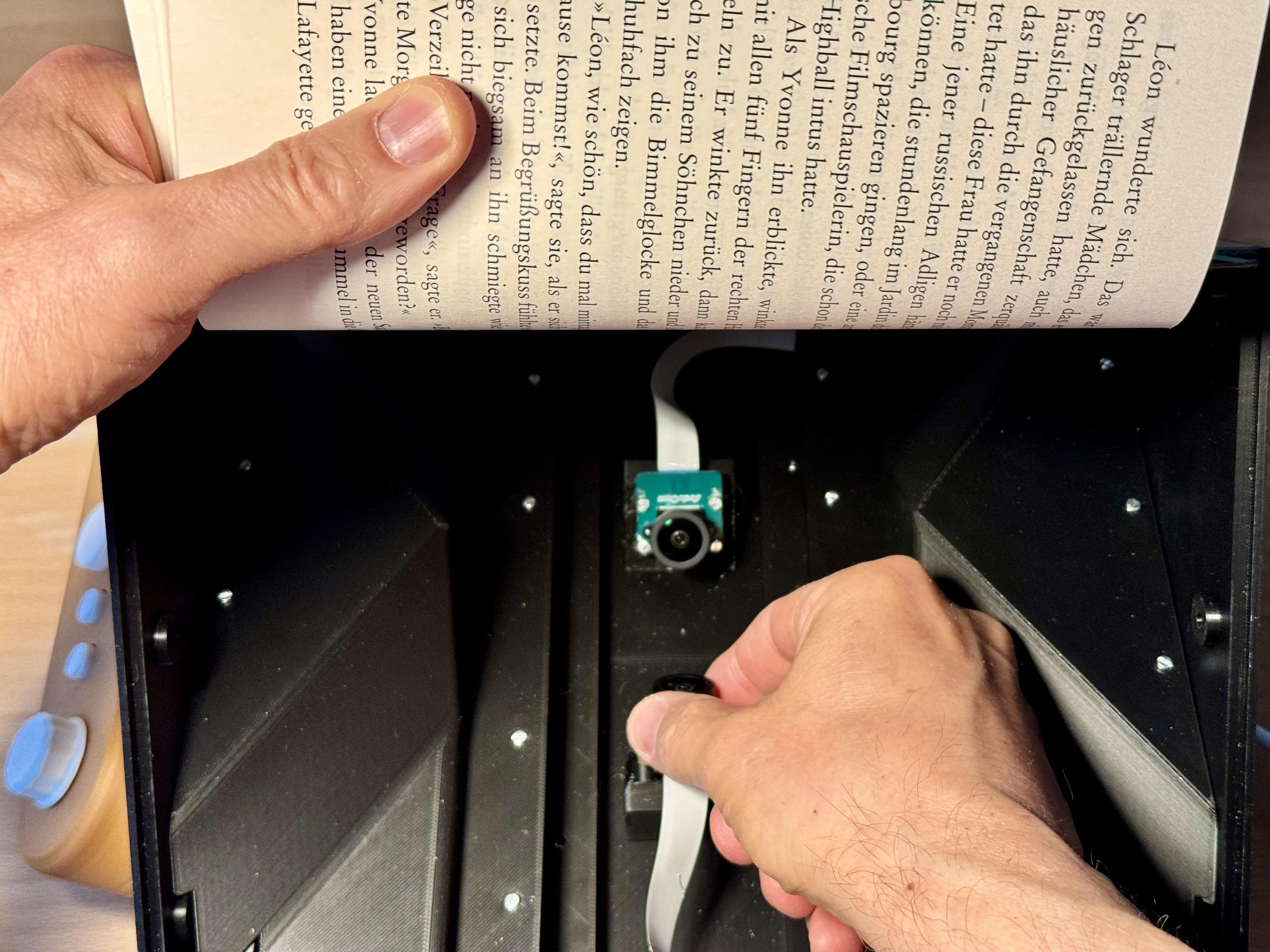
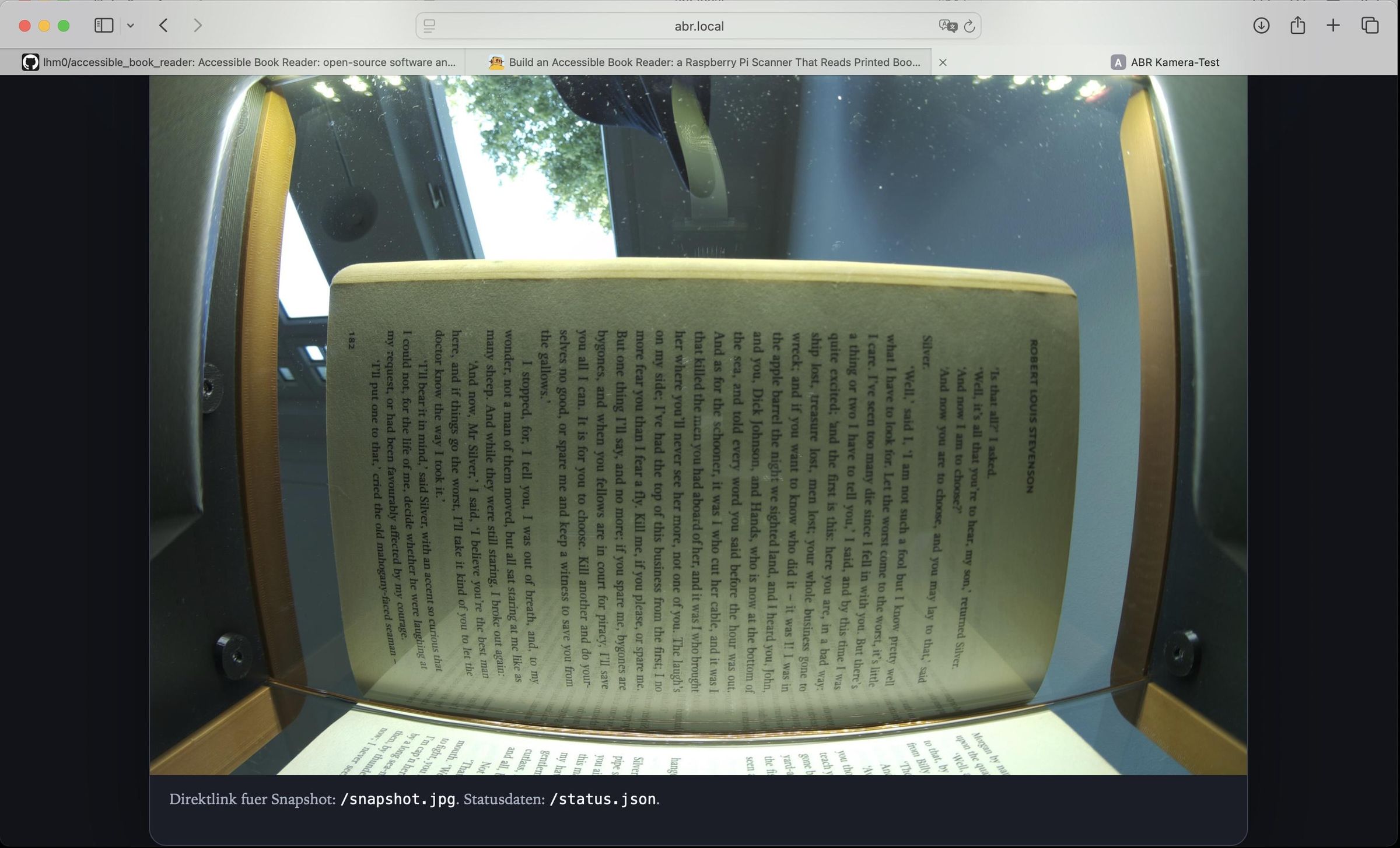
The camera lenses must be focused manually after installation. The repository includes a small camera test server that displays a live image in a web browser. This makes it possible to adjust the lens while observing the result from another computer.
Detailed information is available in the Camera Test Server documentation.
Prepare the Scanner
Insert only one of the two glass panels and place a printed test page on it, as shown in the photograph. A page containing small, high-contrast text is particularly useful for judging sharpness.
Leave the other glass panel removed. The open side provides access to the corresponding camera and allows the lens to be rotated while the test page remains in the correct scanning position.
If the normal ABR service is already running, stop it temporarily so that it does not access the cameras:
Focus the First Camera
On the Raspberry Pi, turn on the left LED row:
Then start the live-view server for camera 0:
On another computer connected to the same network, open this address in a web browser:
If the hostname is not available, replace abr.local with the Raspberry Pi’s IP address.
Carefully rotate the camera lens in small increments while observing the live image in the browser. Allow the image to settle after each adjustment. Continue until the text is as sharp as possible across the relevant page area.
Avoid touching the glass or moving the test page while adjusting the focus. Also make sure that the lens is not unscrewed too far from its holder.
Once the focus has been adjusted correctly, secure the lens with a small drop of adhesive; I used UHU Hart for this purpose.
When done, stop the test server by pressing Ctrl+C in its terminal.
Focus the Second Camera
Move the glass panel and test page to the other side of the scanner. Remove the first panel so that the second camera remains accessible.
On the Raspberry Pi, turn on the off the left and turn on the right LED row:
Start the test server for camera 1 on a different port:
Open the corresponding page in the browser:
Adjust the second lens in the same way until the printed text appears sharp. Secure the lens with a small drop of adhesive, as with the other lens.
After both cameras have been focused, stop the test server, turn off the LEDs, and reinstall both glass panels. Do not change the focus, camera angle or camera height after the distortion calibration performed in the next step, as any mechanical change will invalidate the calibration data.
Restart the normal ABR service when the focusing work is complete:
Calibrate the Image Correction
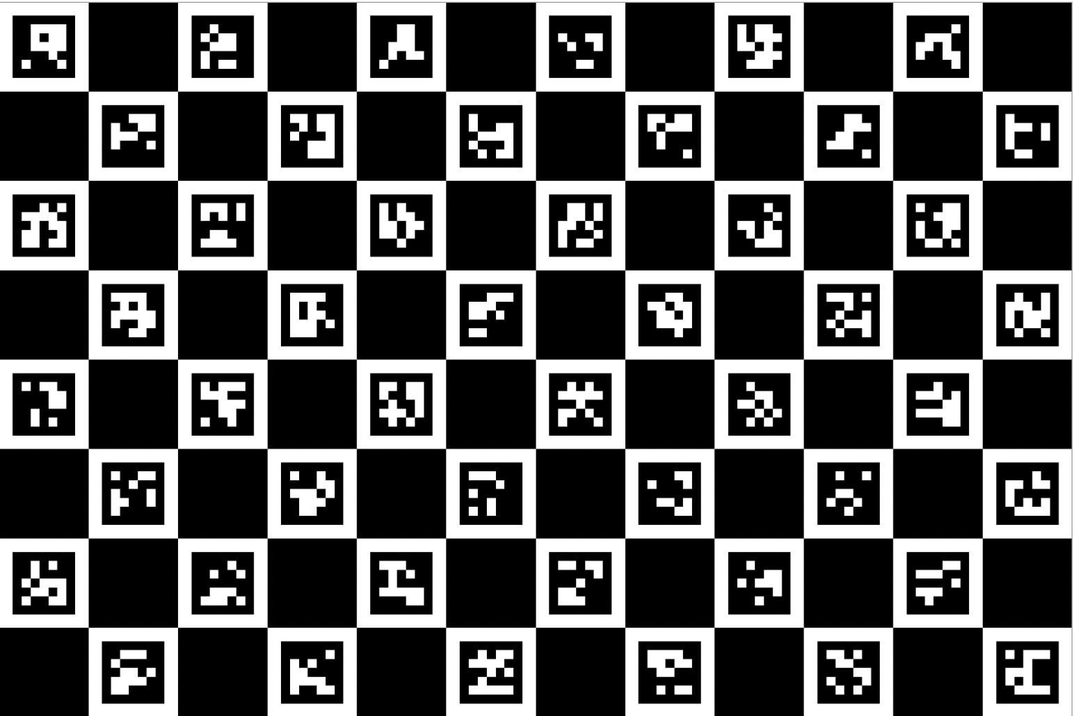
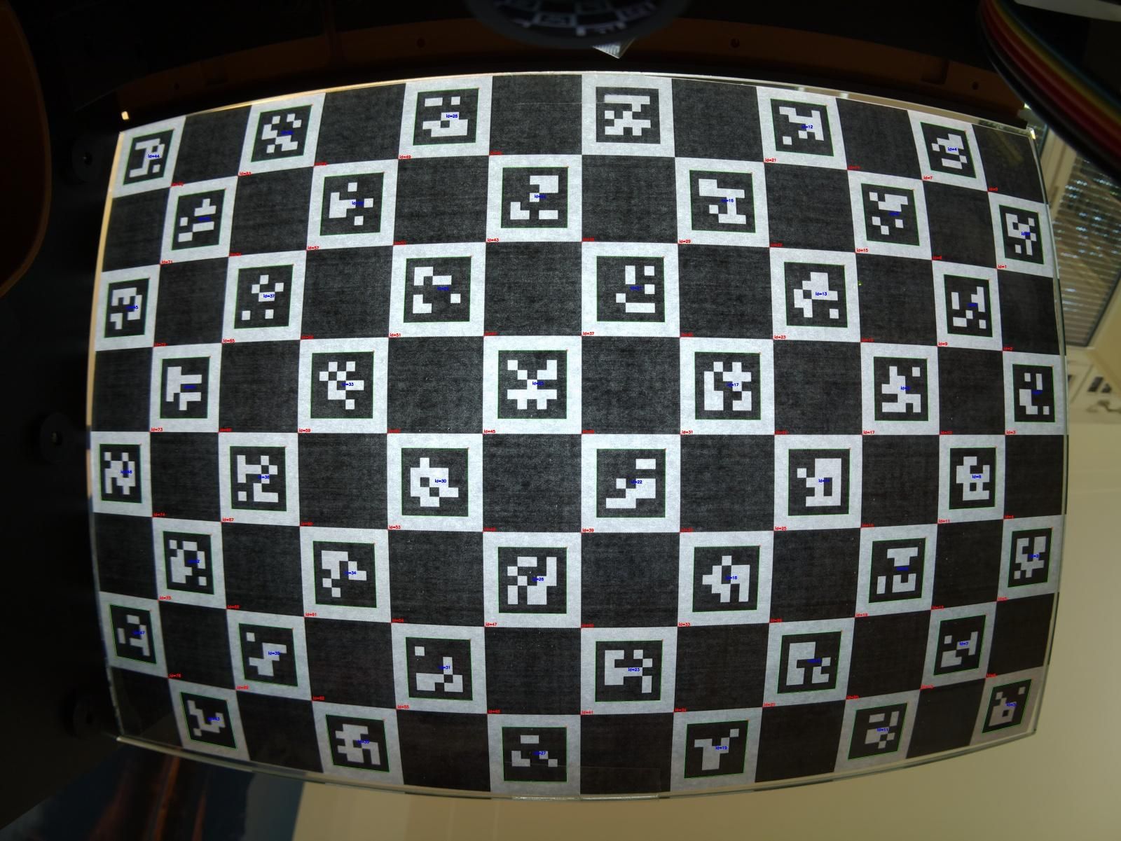
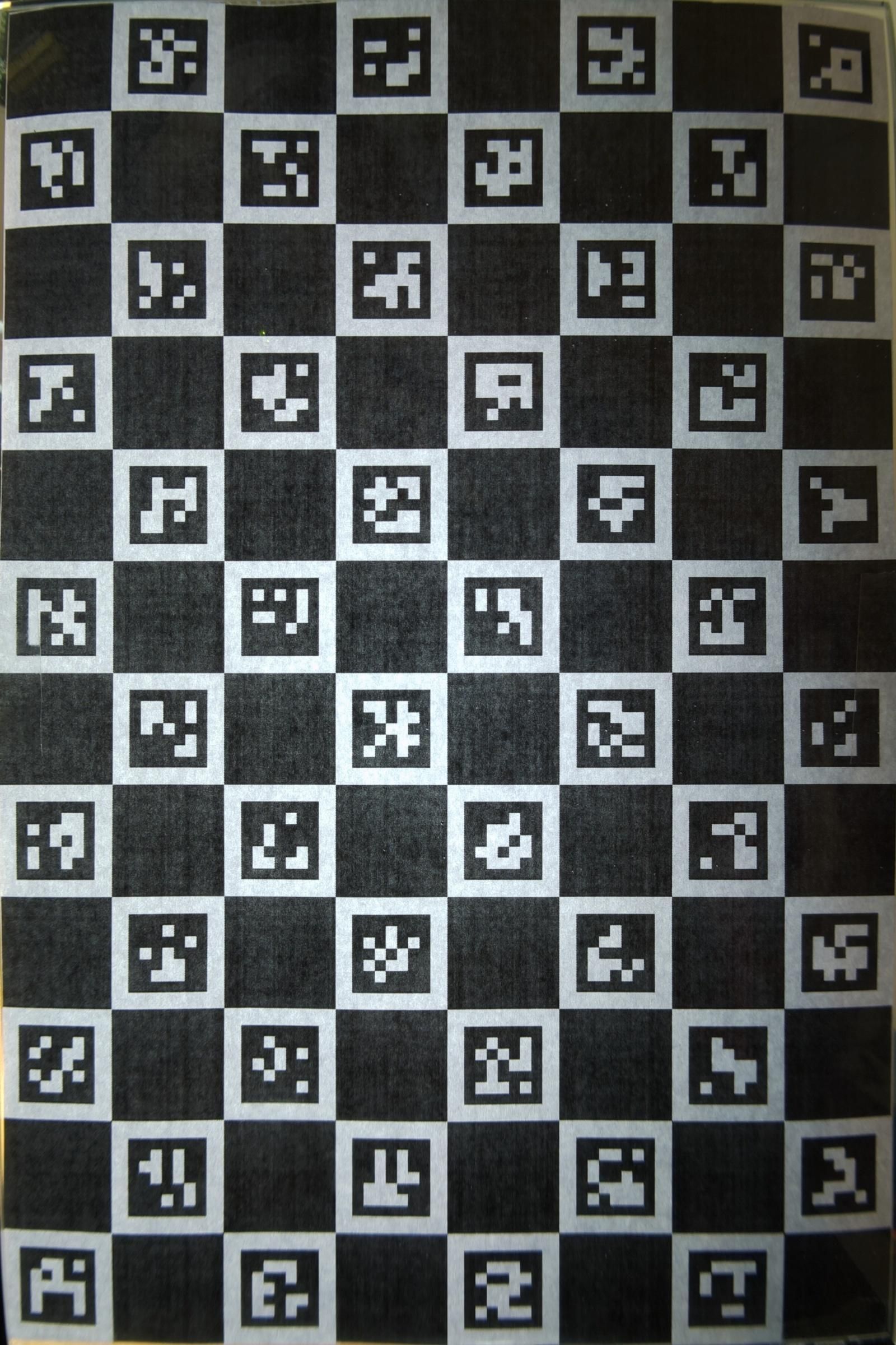
Step 17: Calibrate the Image Correction
The wide-angle camera lenses produce strong barrel distortion. Because the cameras are fixed mechanically, this distortion can be corrected using one calibration image for each camera. The software creates a permanent remapping file that is applied to every captured page.
The complete procedure is documented in:
Prepare the Calibration Board
The repository already contains a printable ChArUco calibration board:
Print this file at 100% scale. Disable options such as “Fit to page” or automatic scaling.
Verify the printed dimensions before continuing:
- Complete board: 160 × 240 mm
- Individual squares: 20 × 20 mm
Attach the printout to a flat and rigid surface. The board must remain as flat as possible during calibration.
If the reference files need to be regenerated, use:
The calibration tools require the OpenCV contrib package:
Capture the Calibration Images
Place the calibration board flat on the scanner in the same position as a book page. The complete pattern should be visible to the camera.
Stop the normal ABR service before accessing the cameras:
Switch on the appropriate LED channel manually:
Start the camera test server at maximum sensor resolution. Do not specify --width or --height, because doing so may exclude parts of the sensor image.
For camera 0:
Open the live image in a browser:
Check that the board is flat, well illuminated and visible across the required page area. Then save a full-resolution snapshot from another computer:
Stop the server with Ctrl+C and switch off the illumination:
Repeat the procedure for camera 1 using the other glass panel and LED channel:
Open:
Save the second calibration image:
Then stop the server and switch off the LEDs:
Generate the Correction Maps
Run the calibration program for camera 0:
Repeat the process for camera 1:
For each camera, the program creates several files, including:
Inspect the detected and rectified preview images. The checkerboard lines should appear straight, and the board should be transformed into a clean rectangular shape without visible discontinuities.
If the calibration was performed on another computer, copy the resulting cam0_planar.npz and cam1_planar.npz files to the same calibration/out/ directory on the Raspberry Pi.
The two .npz files are specific to the individual cameras and their exact mechanical positions. Repeat the calibration whenever the focus, camera angle, camera height or camera module is changed.
Finally, restart the ABR service:
Tune the PN5180 Antennas
The resonance of each external NFC antenna should be adjusted for the best possible reading range. Perform this procedure separately for both readers.
The Raspberry Pi communicates with the PN5180 gateway through the Raspberry Pi Pico. The following command requests the status of both readers and reports any detected ISO 14443A and ISO 15693 tags:
The gateway output contains a separate READER line for each PN5180. The protocol-specific fields indicate whether an ISO 14443A or ISO 15693 tag was detected and show its UID.
Further details about the gateway commands and status output are available in the PN5180 Pico Gateway documentation.
Prepare the Reader
Stop the normal ABR service so that it does not access the gateway while you are performing manual tests:
Remove the internal cover above the NFC reader assemblies to gain access to the antenna-tuning capacitors on the relay boards.
For the initial test, fit a 18 pF capacitor in position C1 and leave C2 unpopulated. C1 and C2 are connected in parallel, so the total tuning capacitance is the sum of both values.
Only solder or replace capacitors while the device is switched off and disconnected from its power supply.
Determine the Initial Reading Range
Use an ISO 14443A tag for the tuning procedure. Place it against the center of the glass panel surrounded by the antenna being tested. Keep the tag parallel to the glass.
Power the device and request the gateway status. To test both readers, use:
The tag should be detected when it is placed directly on the glass.
Now move the tag away from the center of the glass in a direction perpendicular to its surface. Keep the tag parallel to the glass throughout the measurement.
Increase the distance in approximately 1 cm steps and request the reader status after every step. Continue until the tag is no longer detected. Record the greatest distance at which detection was still reliable.
Adjust the Tuning Capacitance
Switch off and disconnect the device before changing any components.
Add a capacitor in position C2. Since C1 and C2 are connected in parallel, adding 2 pF to the initial 18 pF produces a total capacitance of approximately 20 pF.
Power the device again and repeat the complete distance test. Record the maximum reliable range for this capacitance.
Continue testing additional C2 values in increments of approximately 2 pF.
Select the capacitance that provides the greatest reliable reading distance. With a properly tuned antenna, I achieved an ISO 14443A reading distance of approximately 8 cm.
ISO 15693 tags normally provide a considerably greater range. Depending on the tag and antenna alignment, they may still be detected at distances greater than 15 to 20 cm.
Repeat the procedure for the second reader. After both antennas have been tuned, reinstall the internal NFC cover and restart the ABR service:
Test the Complete System
After completing the camera calibration and NFC antenna tuning, the enclosure can be closed permanently.
Carefully clean both sides of the glass panels and remove any dust from the inside of the scanner. Check once more that all cables and antenna wires are correctly routed and cannot be trapped by the outer enclosure parts.
Install the wood-colored front2 and back2 parts and secure them with the appropriate screws. These outer parts overlap the edges of the glass panels and prevent them from falling out. The mechanical assembly is now complete.
Perform a Reading Test
Make sure that the ABR service is running. This will be the case after a re-start. You might test the status:
Place a book fitted with an NFC tag onto the scanner and press the start button.
During image capture, OCR and audio preparation, the device plays a periodic heartbeat chime. This confirms that the command has been accepted and that processing is still in progress.
After processing is complete, the device begins reading the recognized text through the built-in speaker.
Verify that:
- Both pages are captured and read in the correct order.
- The spoken text corresponds to the printed pages.
- The volume control operates correctly.
- Pressing the start button again stops playback.
- Both summary buttons produce the expected spoken summaries once sufficient pages have been scanned.
If the device does not behave as expected, inspect the service status and recent log messages:
Once this test has been completed successfully, the Accessible Book Reader is ready for normal use.
Using the Accessible Book Reader
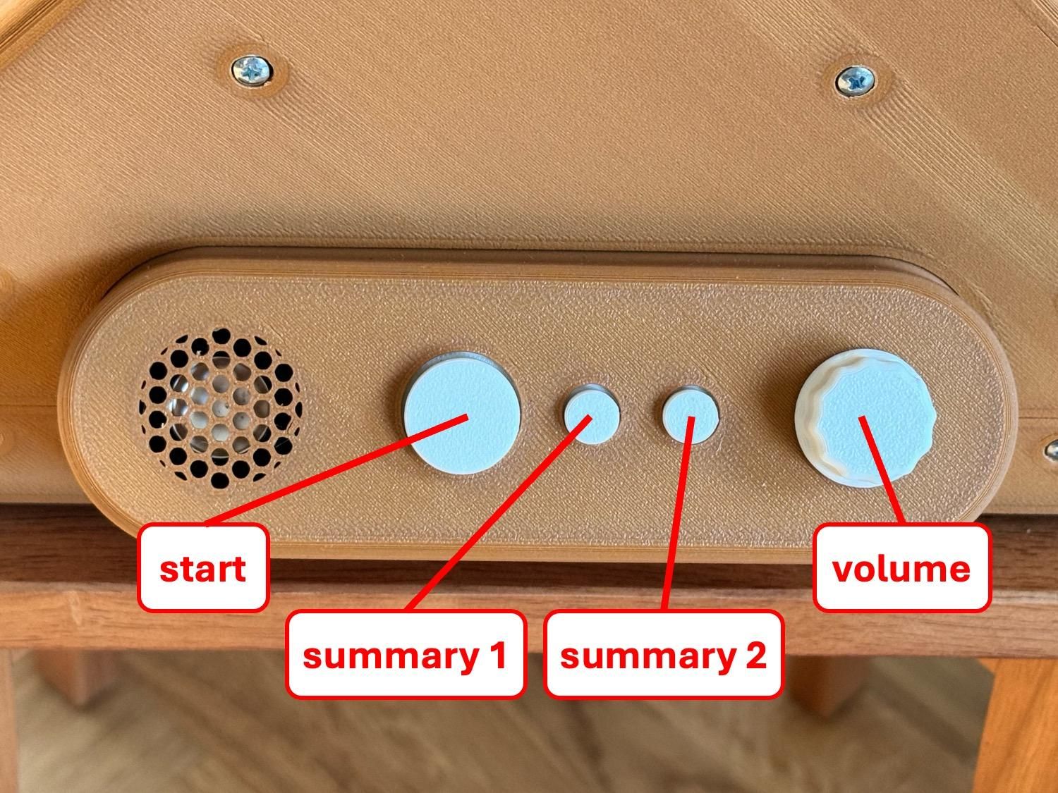
The Accessible Book Reader is operated using only a few tactile controls.
- Read a double page: Place the open book on the scanner and press the Start button. The device captures both pages and begins reading them after processing. Press the Start button again to stop playback.
- Identify the book: The book must have an NFC tag attached to the inside of its cover. Both ISO 14443A and ISO 15693 tags are supported, but ISO 15693 tags are recommended because of their greater reading range and reliability.
- Adjust the volume: Turn the EC11 rotary control while audio is playing.
- Story So Far – Summary 1: Press Summary 1 to generate a chronological recap of the book content scanned so far. The completed section summaries are combined and condensed into a spoken overview.
- Recent Pages – Summary 2: Press Summary 2 to summarize the most recently read part of the book. The device uses the latest completed section and, when present, the pages scanned after that section. Before the first section has been completed, it can create a temporary summary from the available text.
- Delete all stored data for a book: Place the tagged book on the scanner and press the Start, Summary 1 and Summary 2 buttons simultaneously. Follow the spoken instructions. Confirm deletion by pressing the EC11 volume knob, or press one of the function buttons to cancel.
Deleting a book removes its scanned pages, reading history and summaries. This is useful when you want to scan the book again from the beginning and rebuild the summary data from a new, consistent sequence of pages.
Cloud Service Costs
The Accessible Book Reader uses two paid cloud services: Google Cloud Text-to-Speech for generating the spoken audio and Google Gemini for creating summaries.
The standard Google Cloud TTS voices cost USD 4 per one million characters. Assuming an average of approximately 2,500 characters per book page, this corresponds to roughly USD 0.01 per page after the free allowance has been used.
The first four million characters per month are free, corresponding to approximately 1,600 book pages per month. Most individual users are therefore unlikely to exceed the monthly free allowance. Text used for summaries and other generated speech also counts toward the character total. Billing must nevertheless be enabled for the Google Cloud project. See the current Google Cloud Text-to-Speech pricing for details.
Gemini usage is billed separately according to the selected model and the number of input and output tokens processed. The resulting cost depends on the amount of scanned text and how often summaries are requested, so it cannot be expressed as a fixed cost per page. Consult the current Vertex AI pricing information before setting up the service.
Cloud prices and free allowances may change over time.
Conclusion and Future Improvements
The goal of this project was to create a reliable book-reading device that can be operated independently by blind or visually impaired people. The Accessible Book Reader achieves this through a simple tactile interface, automatic book identification and a largely automated process from image capture to spoken audio.
The device works reliably, and the OCR system produces comparatively few recognition errors under normal conditions. The essential development goals—simple operation, dependable page recognition and good-quality speech output—have therefore been achieved.
There is still room for improvement. At present, approximately 25 seconds pass between pressing the Start button and the beginning of audio playback. This is acceptable in practice, especially because the heartbeat chime indicates that processing is still underway. Nevertheless, reducing this delay would improve the user experience. The main limitation is currently the processing performance of the Raspberry Pi 5 during image preparation and OCR.
The Google Cloud TTS backend provides clear and natural speech using the selected standard voices. In my tests, its quality was noticeably better than that of the evaluated offline TTS solutions. More natural cloud voices are now available, but their substantially higher operating costs are difficult to justify for this application. The ABR therefore continues to use the more economical standard voices.
Open Source and Open Hardware
The Accessible Book Reader is an open-source and open-hardware project. My aim is to make printed books more accessible and, through this work, help improve the everyday lives of blind and visually impaired people.
Anyone can study the design, build the device and contribute improvements. All software, firmware, electronics, mechanical design files and documentation are available in the GitHub repository.
Please review the licensing information in the repository before reproducing, modifying or distributing the project. The public licences permit commercial use but include copyleft obligations for distributed derivatives. I am also open to discussing separate commercial licensing arrangements and future development cooperation.
I hope this project provides both a useful device and a practical foundation for further work on accessible reading technology.