Build an Automatic Water Pump Controller Without a Microcontroller
by DidierKabelu in Circuits > Electronics
58 Views, 0 Favorites, 0 Comments
Build an Automatic Water Pump Controller Without a Microcontroller
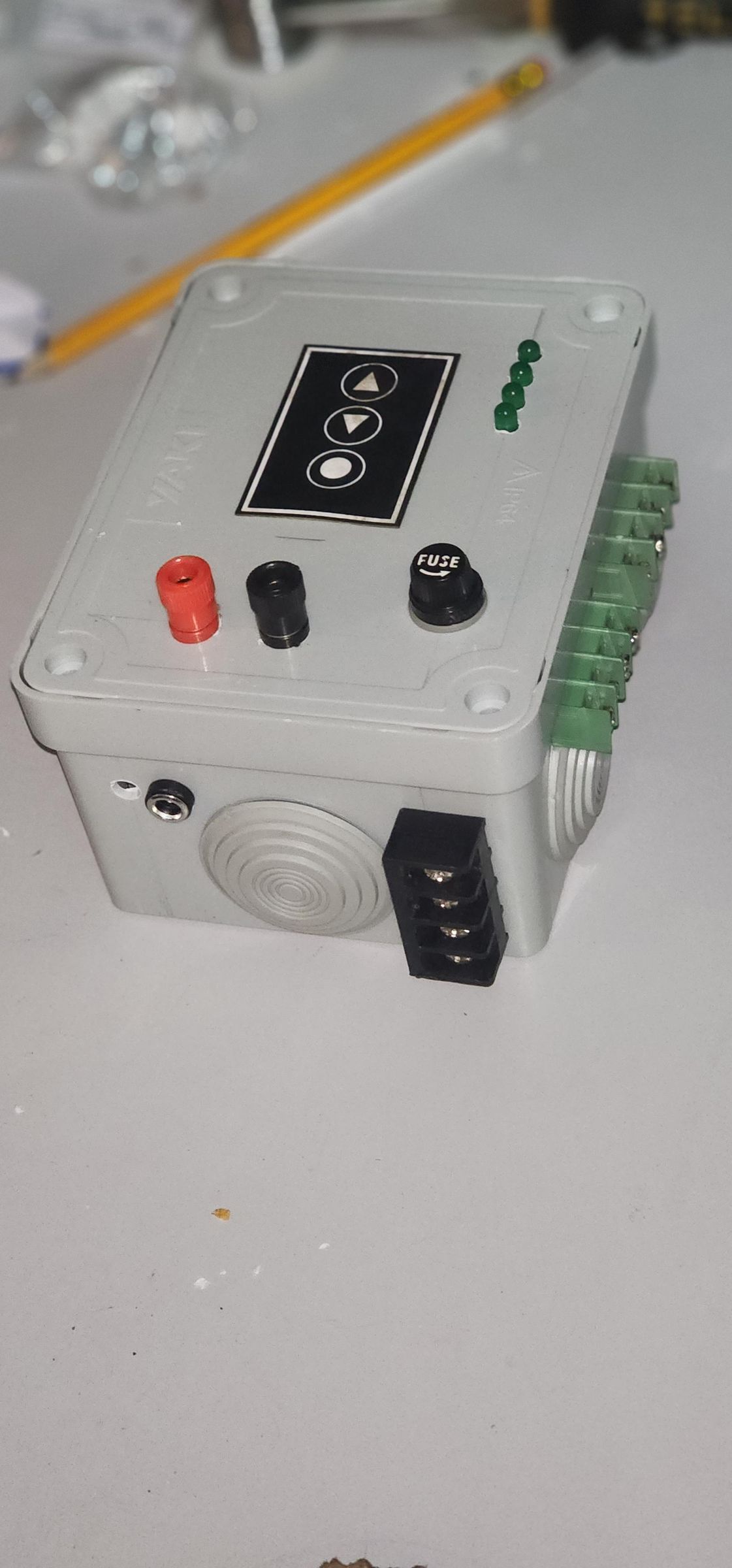
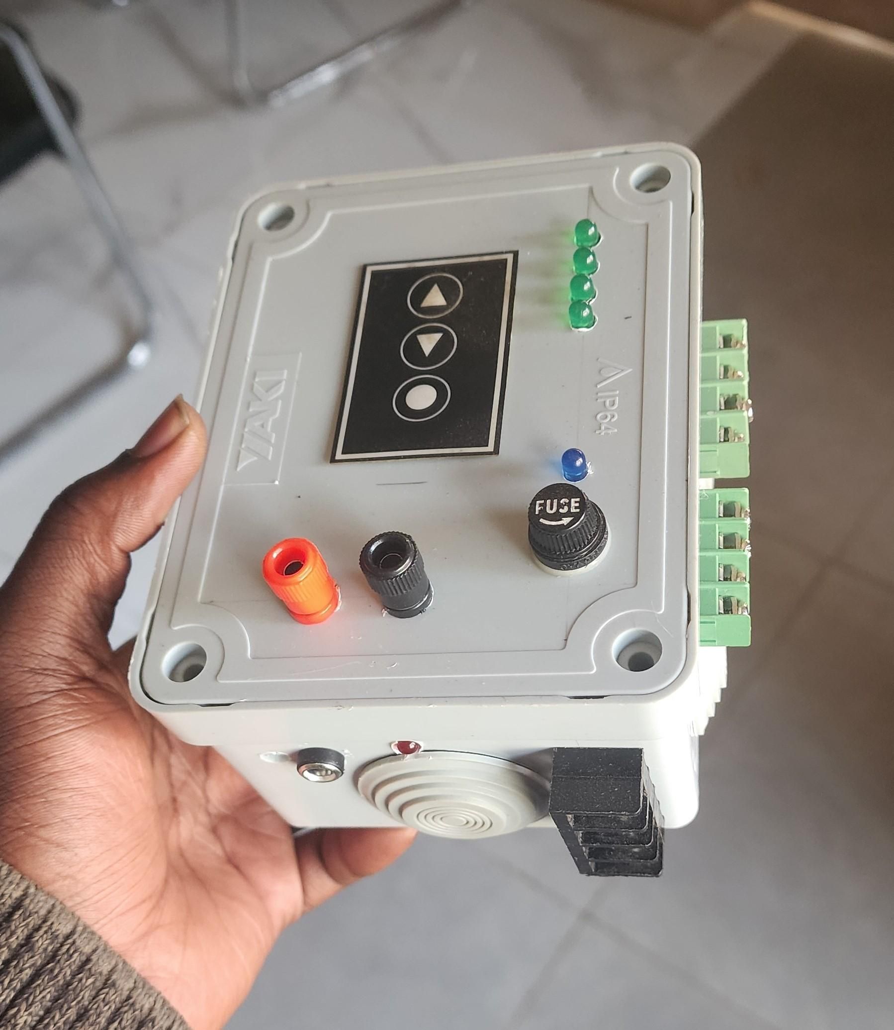
Imagine having to constantly monitor a water tank to make sure the pump is turned on when the water level is low—and turned off before the tank overflows.
What if the pump could handle this automatically?
In this project, we’ll build an automatic water pump controller that detects the water level and switches the pump ON or OFF automatically—using only logic ICs, without a microcontroller.
The system starts the pump when the water level falls below a preset level and stops it when the tank is full. LEDs also provide a visual indication of the water level.
What We’ll Build
This project combines water level detection, visual level indication, automatic pump control, and manual control into a single system.
The controller monitors four water levels—25%, 50%, 75%, and 100%. When the water level falls below the selected threshold, the pump starts automatically. When the tank reaches 100%, the pump stops.
No Arduino. No ESP32. No programming. Just simple electronic components and logic ICs.
What You’ll Learn
By the end of this project, you’ll know how to:
- Detect different water levels using simple probes and a ULN2003 IC.
- Build a circuit that automatically controls a water pump.
- Set a preset water level that triggers the pump.
- Create a simple visual indicator for the water level.
- Build and test the complete system without using a microcontroller.
Supplies
1.Main Electronic Circuit Components
This section covers the logic, detection, control, and display components mounted on the circuit board.
- 1 × ULN2003 — Darlington transistor array (probe interface / indicator driver)
- 1 × CD4071 — Quad 2-input OR gate IC
- 1 × CD4081 — Quad 2-input AND gate IC
- 1 × Electromagnetic relay — Power switching interface
- 4 × Green LEDs — Water level visual indicators
- 4 × 1 kΩ resistors
- 5 × 10 kΩ resistors
- 1 × Push button — Manual start trigger
- 1 × Breadboard or Veroboard — Prototyping PCB
- Jumper wires / connecting wires — Internal wiring
2. Enclosure & Final Prototype Assembly
This section covers the outer housing, panel-mounted connectors, and external protection.
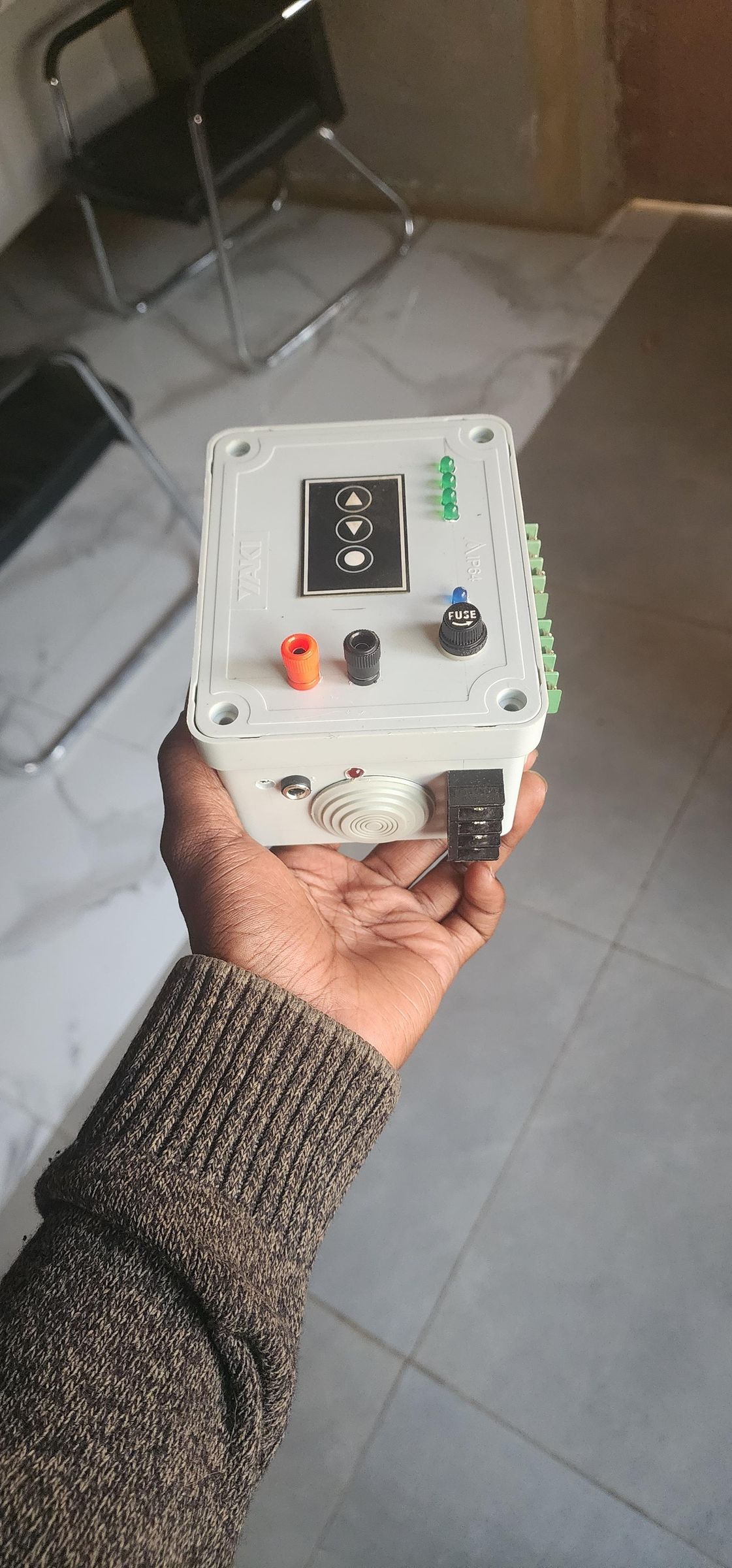
- 1 × Junction box 150 × 110 × 70 mm — Main enclosure
- 3 × 4-Pin 8.5mm Pitch PCB Screw Terminal Connectors (Green)
- 1 × 4-Pin Barrier Terminal Block / Screw Terminal Strip (Black panel-mount block)
- 2 × Panel Mount Banana Sockets / Binding Posts (1 × Red, 1 × Black) — Power / battery connectors
- 1 × Panel Mount DC Power Jack / Socket — Alternate power inlet
- 1 × Panel Mount Fuse Holder (with 1 × Fuse)
- 1 × Power switch
- 1 × Control Panel Sticker / 3-Button Membrane Overlay — Front panel graphic
Safety Warning
This project can be used to control a 220 V AC water pump. Mains voltage is dangerous and potentially lethal.
- Never work on the 220 V side while the circuit is powered.
- Keep the low-voltage control circuit electrically isolated from the mains side.
- Use a relay rated for the pump’s voltage and current.
- Make sure all mains connections are properly insulated and enclosed.
- If you are not qualified to work with mains electricity, ask a qualified electrician to handle the 220 V wiring.
For testing and learning, you can first use a low-voltage load instead of a 220 V pump.
Understand the Circuit
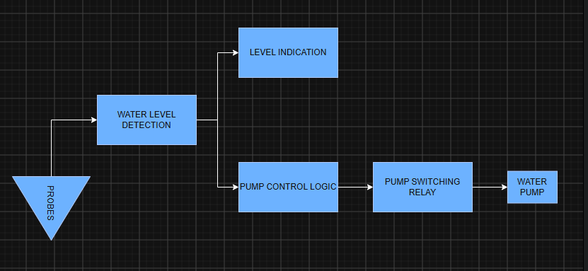
Water Level Detection → Level Indication → Pump Control Logic → Pump Switching – Relay
1. Water Level Detection
The water level is detected using simple metal probes placed at different heights inside the water tank.
Four wires connected to the inputs of the ULN2003 are used as level probes. Another wire connected to 12 V is placed in the tank as a common water-level electrode.
When the water reaches a probe, it creates an electrical path between the 12 V common electrode and that probe. This activates the corresponding input of the ULN2003.
Each probe therefore represents a specific water level:
- S1 → 25%
- S2 → 50%
- S3 → 75%
- S4 → 100%
2. Level Indication
The four corresponding outputs of the ULN2003 drive four green LEDs. The LEDs are connected between VCC and the ULN2003 outputs, so they turn ON when the corresponding output is pulled LOW.
When a probe is in contact with water, the corresponding ULN2003 output becomes LOW and its LED turns ON.
Therefore, when the tank is full:
Water Level ULN2003 Output LED
S1 — 25% LOW LED 1 ON
S2 — 50% LOW LED 2 ON
S3 — 75% LOW LED 3 ON
S4 — 100% LOW LED 4 ON
As the water level falls, the upper probes lose contact with the water. Their corresponding ULN2003 outputs return HIGH, causing their LEDs to turn OFF.
For example:
- Below 100% → Output 4 HIGH → LED 4 OFF
- Below 75% → Output 3 HIGH → LED 3 OFF
- Below 50% → Output 2 HIGH → LED 2 OFF
- Below 25% → Output 1 HIGH → LED 1 OFF
This provides a simple visual indication of the water level while also generating the logic signals used by the pump control circuit.
3. Pump Control Logic
The pump control circuit is built using one OR gate and one AND gate.
The logic is described by the following equation:
S_PUMP = S4 × (S2 + PUSH BUTTON)
Where:
- S2 = 50% water-level signal
- S4 = 100% water-level signal
- PUSH BUTTON = manual pump command
- S_PUMP = pump control signal
The two inputs S2 and PUSH BUTTON are first combined by the OR gate. The output of this OR gate is then combined with S4 through the AND gate.
Automatic Operation
When the water level falls below the preset 50% level, S2 becomes HIGH. The OR gate therefore produces a HIGH output.
Because the tank is not full, S4 is also HIGH. The AND gate then produces a HIGH S_PUMP signal, turning the pump ON.
As the tank fills and the water level rises above 50%, S2 returns LOW. However, the feedback path keeps the pump command active while the tank is being filled.
When the water reaches the 100% probe, S4 becomes LOW. Since S4 is an input of the AND gate, this forces S_PUMP LOW, turning the pump OFF regardless of the state of S2 or the push button.
The automatic sequence is therefore:
Below 50% → S2 HIGH → Pump ON → Water rises → 100% reached → S4 LOW → Pump OFF
Manual Operation
The push button provides a manual way to start the pump.
When the button is pressed, the OR gate produces a HIGH output. However, the AND gate allows this command to reach S_PUMP only when S4 is HIGH, meaning that the tank is not full.
Therefore:
Tank not full + Push Button pressed → Pump ON
If the tank is already full, S4 is LOW, so the AND gate blocks the command and the pump cannot be started.
The automatic starting level can be changed by selecting a different level signal:
- S1 → 25% starting level
- S2 → 50% starting level
- S3 → 75% starting level
The 100% probe (S4) remains the safety stop condition that prevents the pump from running when the tank is full.
4. Pump Control Logic — Truth Table
The pump control logic is defined by:
S_PUMP = S4 × (S2 + PUSH BUTTON)
The following truth table shows how the OR and AND gates determine the pump command :
S4 S2 PUSH BUTTON S2 + PUSH BUTTON S_PUMP
0 0 0 0 0
0 0 1 1 0
0 1 0 1 0
0 1 1 1 0
1 0 0 0 0
1 0 1 1 1
1 1 0 1 1
1 1 1 1 1
Where:
- S4 = 0 → tank is full → pump is forced OFF.
- S4 = 1 → tank is not full → the pump can be activated.
- S2 = 1 → water level is below 50%.
- PUSH BUTTON = 1 → manual start command.
- S_PUMP = 1 → pump ON.
- S_PUMP = 0 → pump OFF.
This shows that S4 acts as an enable signal for the entire pump-control logic. Even if S2 or the push button requests the pump to start, the AND gate blocks the command whenever the tank is full.
The feedback path is then used to maintain the pump command while the tank is being refilled.
5. Why Use the ULN2003?
The ULN2003 is used as the interface between the water-level probes and the rest of the control circuit.
When water reaches a probe, it creates a conductive path between the 12 V common electrode and the probe. This produces a relatively small current that activates the corresponding input of the ULN2003.
Each input controls a Darlington transistor inside the ULN2003. When the transistor is activated, it pulls its output LOW.
This gives us a simple and useful interface:
Water probe → ULN2003 input → Darlington transistor → LOW output
The LOW output can then be used to:
- Turn ON the corresponding level LED.
- Provide a clear logic signal to the pump-control circuit.
- Handle multiple water-level probes using a single IC.
The ULN2003 is particularly convenient for this project because it provides seven Darlington transistor channels in a single IC, allowing several level probes and indicators to be handled with very few components.
In this design, the ULN2003 therefore performs two functions at the same time: water-level signal conditioning and low-side switching for the level indicators.
5. Pump Switching – Relay
The logic circuit itself cannot directly drive a 220 V AC pump. Therefore, an electromagnetic relay is used as the interface between the low-voltage control circuit and the pump's power circuit.
The control signal energizes the relay coil, causing its contacts to switch the pump ON or OFF.
This provides electrical isolation between the low-voltage control electronics and the high-voltage pump circuit.
The relay must be properly rated for the voltage and current of the pump, and all 220 V connections must be safely insulated and enclosed.
Downloads
Build the Circuit
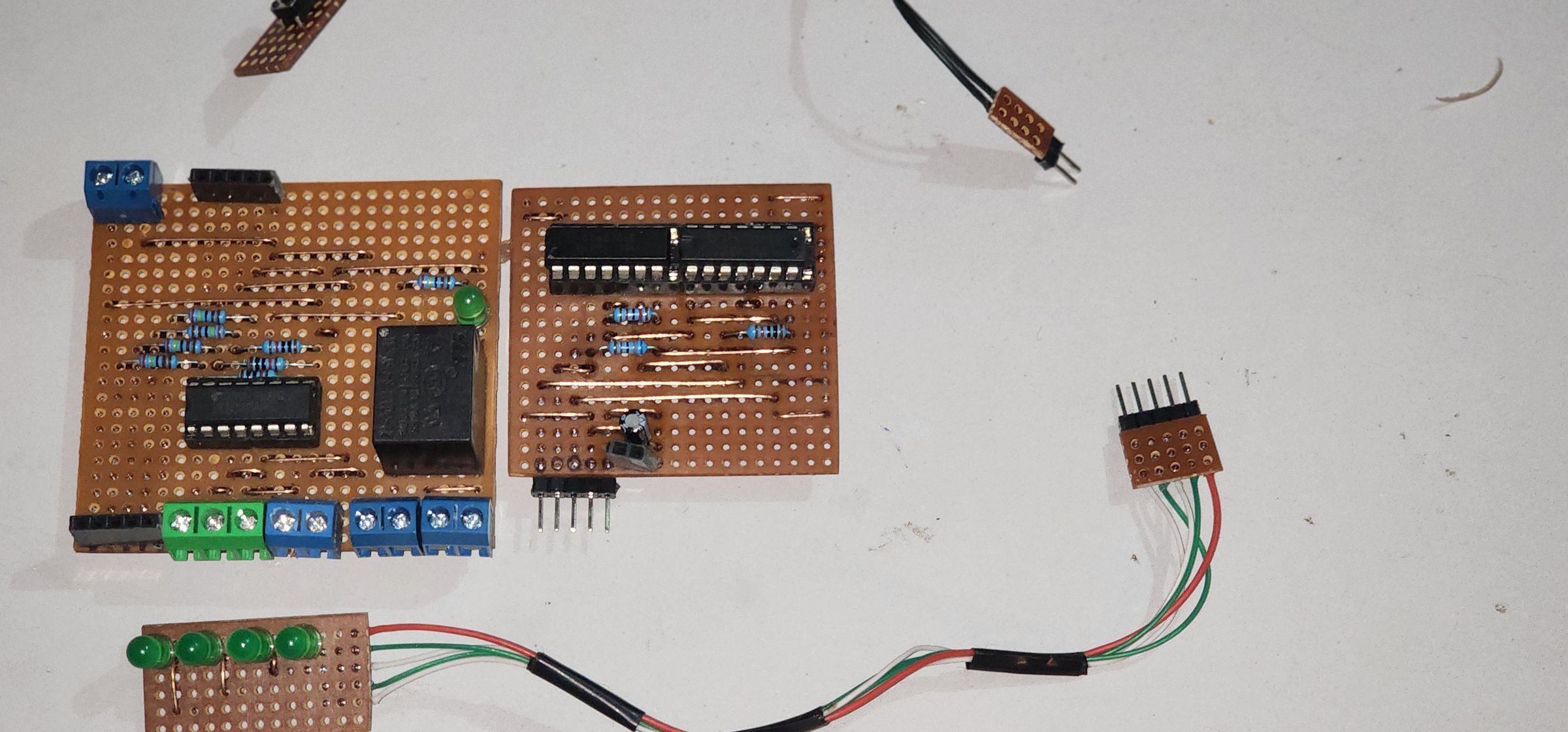
Now that the water level probes are in place, build the electronic circuit according to the schematic.
Connect all components as shown and double-check the wiring before applying power.
For the 220 V AC section, follow the safety precautions from Step 1.
Install the Water Level Probes
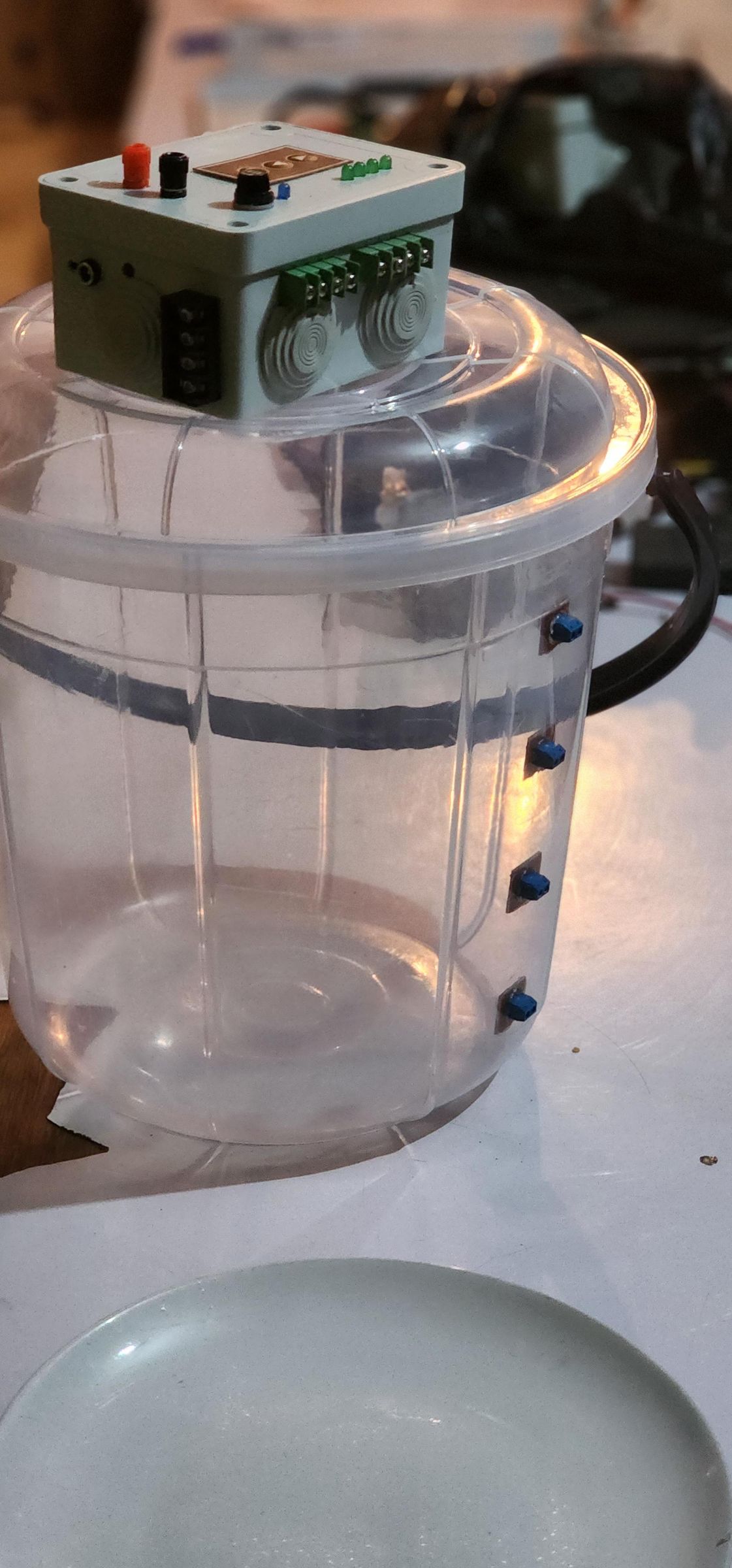
Install four water-level probes at different heights inside the tank. Each probe represents a specific water level:
- Probe 1 → 25%
- Probe 2 → 50%
- Probe 3 → 75%
- Probe 4 → 100%
For each level, install a +12 V common electrode slightly below its corresponding level probe. When the water reaches the probe, it creates a conductive path between the common electrode and the level probe.
Repeat this arrangement for all four levels:
- 25% → Common 1 + Probe 1
- 50% → Common 2 + Probe 2
- 75% → Common 3 + Probe 3
- 100% → Common 4 + Probe 4
Connect the four common electrodes together and connect them to +12 V. Each level probe has its own wire connected to the corresponding ULN2003 input.
This requires five wires between the tank and the control circuit: one +12 V wire for the four common electrodes and four probe wires.
Use corrosion-resistant conductive material for the electrodes. Keep the probes clean and properly spaced to ensure reliable detection, as water conductivity can vary depending on its mineral content.
Test the Circuit
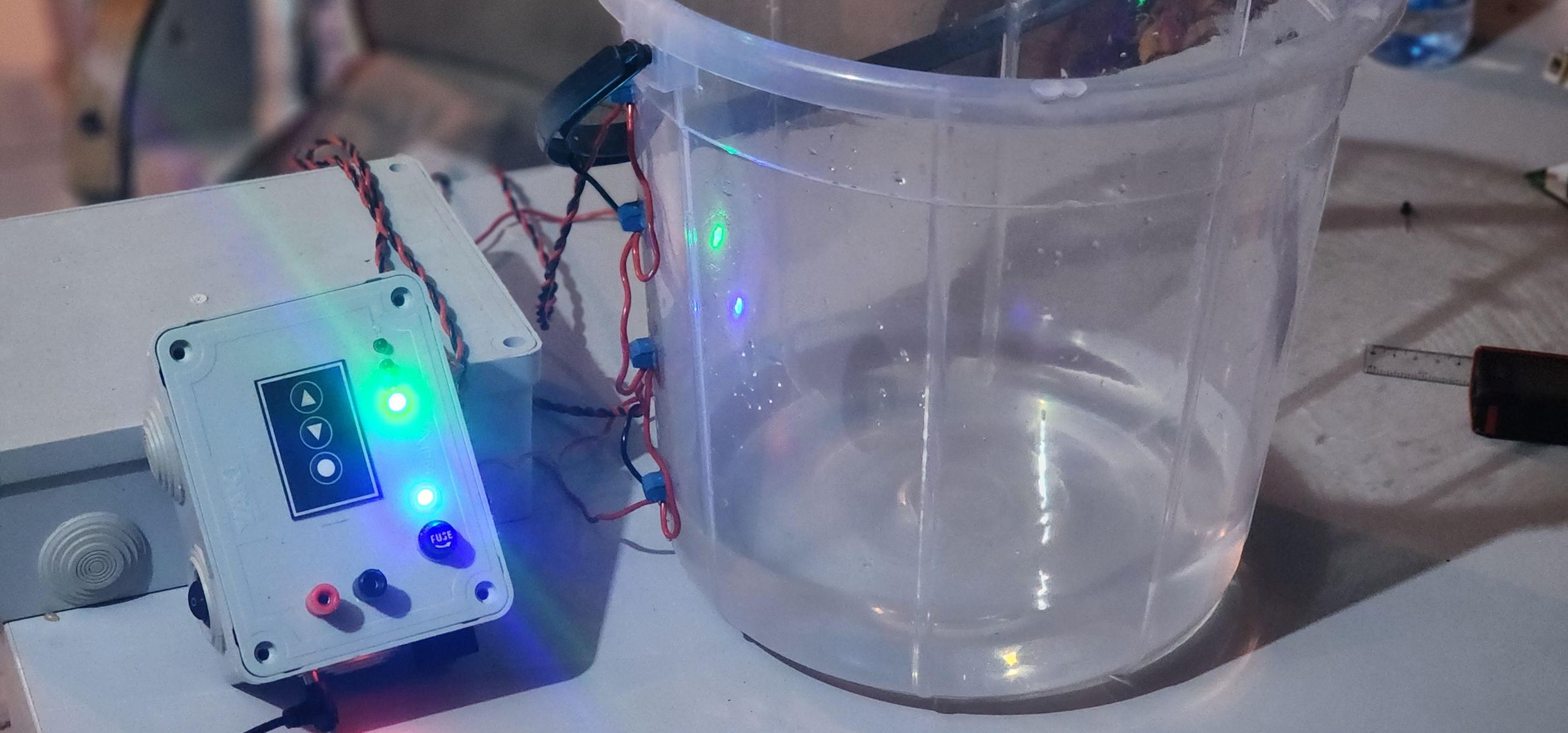
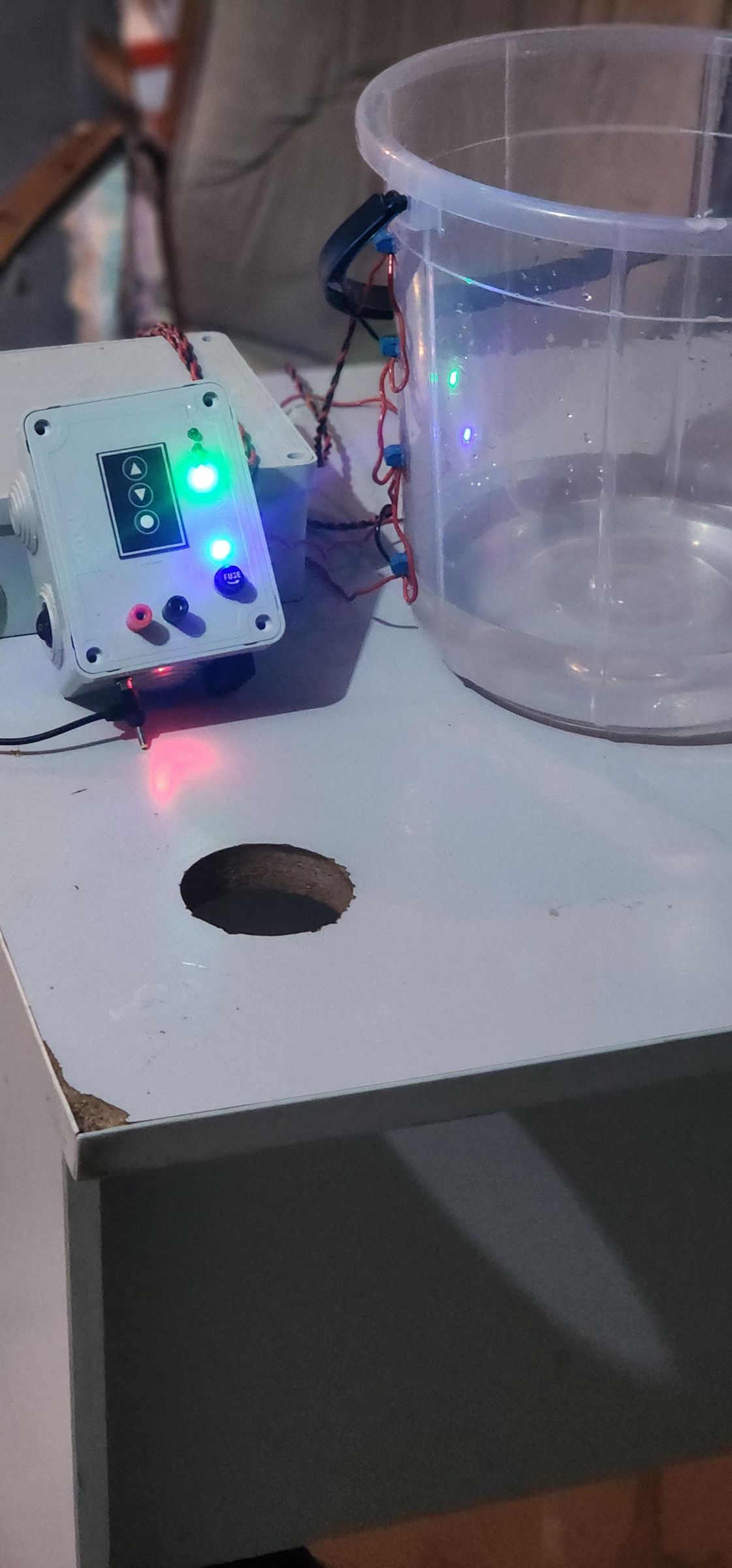
Slowly fill the tank and verify that the LEDs turn ON as the water reaches each level:
- 25% → LED 1 ON
- 50% → LED 2 ON
- 75% → LED 3 ON
- 100% → LED 4 ON
Then slowly lower the water level and verify that the LEDs turn OFF in the reverse order.
Finally, test the pump control:
- The pump starts automatically when the water level falls below the preset level.
- The pump continues running while the tank is being refilled.
- The push button can manually start the pump when the tank is not full.
- The pump stops automatically when the tank reaches 100%.
- The pump cannot be started when the tank is already full.
If all these tests work as expected, the automatic water pump controller is ready to use
Click here to watch the final test video.
Understand Limitations
Although this system is simple and practical, it has some limitations:
- Water conductivity: The probes rely on the electrical conductivity of the water. Very low-conductivity water may result in unreliable level detection.
- Electrode corrosion: Continuous contact with water can cause the electrodes to corrode over time. Corrosion-resistant materials are recommended.
- Probe maintenance: The electrodes should be inspected and cleaned periodically to maintain reliable detection.
- Relay and pump rating: The relay must be properly rated for the pump, including its starting current.
- Mains voltage: The 220 V AC section requires proper insulation, enclosure, protection, and installation by a qualified person when necessary. :