Build an IR Light Emitter for IR Receivers
by DidierKabelu in Circuits > Electronics
76 Views, 0 Favorites, 0 Comments
Build an IR Light Emitter for IR Receivers
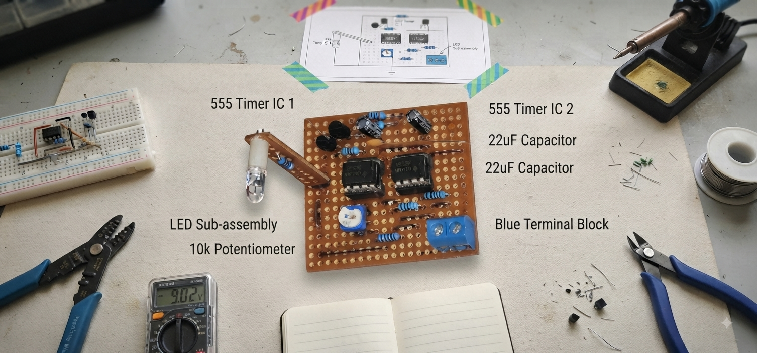
Imagine you want to build an infrared beam barrier to detect when an object crosses a path. Naturally, you need two circuits: an IR transmitter and an IR receiver.
For the receiver, the first component that probably comes to mind is a photodiode. And technically, it can detect infrared light.
But there is a problem.
A simple photodiode cannot distinguish between the IR signal from your transmitter and the infrared radiation coming from the sun, lamps, and other sources. Your system could therefore produce false detections.
So, how can we make the receiver detect only our IR signal?
This is where integrated infrared receivers with built-in filtering come in.
These receivers combine a photodiode, amplification, filtering, and signal processing in a single package. Their internal filtering is designed to detect infrared signals modulated at a specific carrier frequency, making them much less sensitive to continuous or unwanted infrared sources such as sunlight and ambient lighting.
Different receivers are designed for different carrier frequencies. For example, TSOP36 receivers are designed for approximately 36 kHz, while TSOP38 receivers are designed for approximately 38 kHz. Other variants are available for frequencies such as 30 kHz, 40 kHz, or 56 kHz.
This also imposes a requirement on our transmitter: we cannot simply turn the IR LED on and off. We need to modulate the emitted infrared light at the carrier frequency expected by the receiver.
In our case, since we are using a 38 kHz IR receiver, the transmitter must generate a 38 kHz carrier.
In this project, we will therefore build a simple 38 kHz IR emitter designed to work with 38 kHz IR receivers such as the TSOP38.
What You Will Learn
By the end of this tutorial, you will be able to:
- Understand how an IR emitter built around two astable oscillators works.
- Calculate and select the component values according to the type of IR receiver being used.
- Build and test the complete IR emitter circuit.
Supplies
Supplies
- 2 × NE555 timer IC
- 1 × IR LEDs
- 2 × 1 kΩ resistor
- 1 × 6.8 kΩ resistor
- 1 × 22 kΩ or 50 kΩ potentiometer
- 1 × 10 µF capacitor
- 1 × 1 nF capacitor
- 1 × 2kΩ, 1/4 W resistor
- 1 × 12 V DC power supply
- Breadboard
- Jumper wires
- Oscilloscope for testing and frequency adjustment
Understand the Circuit
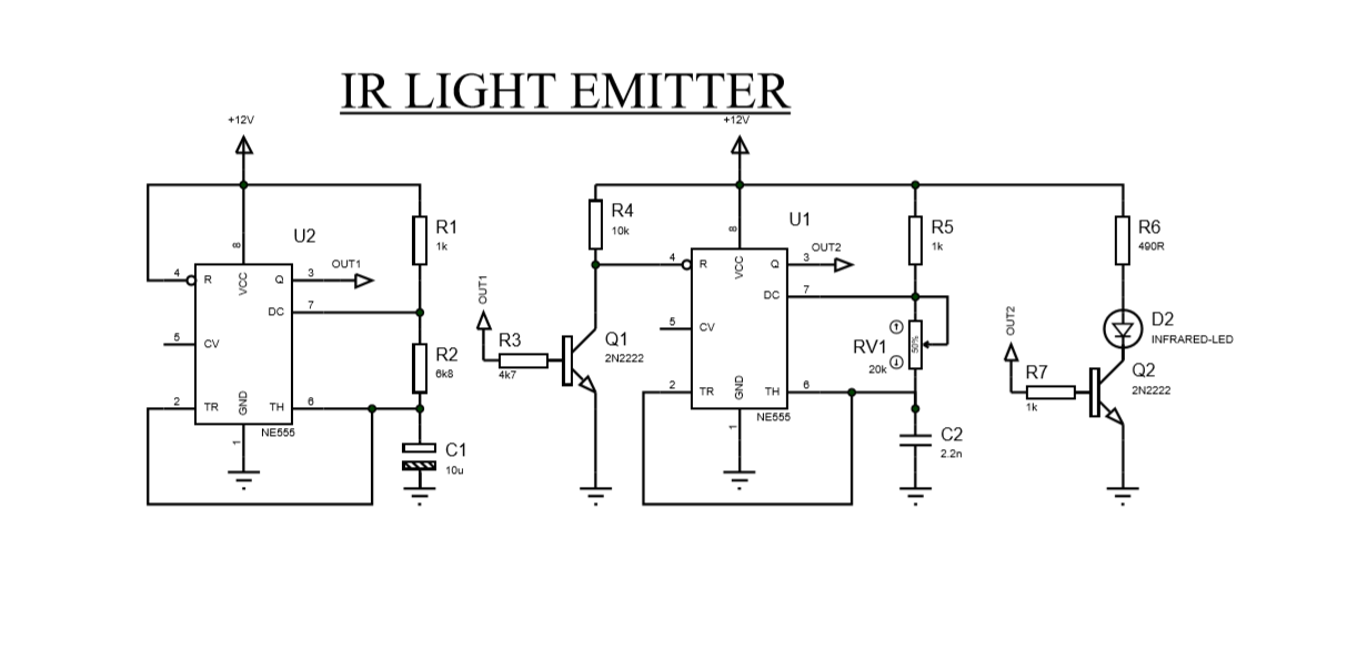
This IR emitter is built around two NE555 astable oscillators.
The first oscillator runs at a low frequency of approximately 10 Hz and controls the second oscillator, which generates the 38 kHz carrier signal.
The second NE555 is controlled through its RESET pin. It only generates the 38 kHz signal when the output of the first oscillator is HIGH. As a result, the IR LED does not emit a continuous 38 kHz signal, but rather short bursts of 38 kHz pulses separated by pauses.
These pauses are important because the TSOP38 is designed to detect bursts of modulated IR rather than a continuous 38 kHz signal. Continuous transmission can cause its automatic gain control (AGC) and interference suppression mechanisms to reduce or reject the signal, preventing the receiver from responding correctly.
The first oscillator therefore acts as a burst generator, while the second oscillator generates the 38 kHz carrier used by the IR receiver.
Dimension the Two Astable Oscillators
2.1 — 10 Hz Astable Oscillator
This oscillator is built around two resistors (R1 and R2) and a capacitor (C). This RC network determines the oscillation frequency.
The period is:
T = T(ON)+ T(OFF)
where T(ON) is the time during which the output is HIGH, and T(OFF) is the time during which the output is LOW.
The ratio between TON and the total period T is called the duty cycle (D):
D = T(ON)/ T
For this project, we want a duty cycle close to 50%.
For a standard NE555 astable configuration:
T(ON) = 0.69(R1+R2)C (1)
T(OFF) = 0.69 x R2 xC (2)
Therefore:
T = 0.69(R1+2R2)C (3)
Since:
f = 1/T
We want:
f=10 Hz
which gives:
T= 1/10 = 0.1s
Let's choose convenient values for the capacitor and R1.
C = 10uF = 0.00001F
R1 = 1K = 1000𝝮
We chose 1 kΩ for R1 to obtain a duty cycle close to 50%.
Then, let’s calculate R2.
From Equation (1), we get:
2R2 = (T /0.69C1) - R1
R2 =(( T/0.69xC1) - R1)/2
R2 =(( 0.1/ 0.69x0.00001) - R1)/2
= 6746.37 𝝮
= 6.7K𝝮
We can use the standard 6.8 kΩ value.
So our 10 Hz oscillator will use approximately:
- R1 = 1 kΩ
- R2 = 6.8 kΩ
- C = 10 µF
This gives a frequency of approximately 9.9 Hz with a duty cycle of about 53%, which is close to our target of 50%.
2.2 — 38 kHz Astable Oscillator
The second NE555 generates the 38 kHz carrier that drives the IR LED.
We use the same astable configuration:
T=0.69(R5+2R6)C
and:
We want:
f =38 kHz = 38000 Hz
T= 1/38000 = 0.000026s
For a 38 kHz carrier:
Let's choose convenient values for the capacitor C2 and R5.
C2 = 1nF = 0.000000001F
R5 = 1k = 1000Ω
Then, let’s calculate R6:
R6 =(( T/0.69C1 )- R5)/2
R6 =(( 0.00002/0.69xC1 )- R5)/2
= 18840Ω
= 18.8kΩ
So, we are going to use a 20 kΩ potentiometer, which is close to the calculated 18.5 kΩ value, to adjust the frequency.
So our 38KHz oscillator will use approximately:
- R5 = 1 kΩ
- R6 = 20 kΩ
- C = 1 nF
Dimension the IR LED Current-Limiting Resistor
Our emitter uses one IR LED .We want the LED to emit a strong infrared signal in order to increase the range of the emitter.
To limit the current, we use a series resistor with the LED.
Using Kirchhoff's Voltage Law:
VCC - VLED - (R x ILED)= 0
The target LED current is 20mA(0.02A):
R = (VCC - VLED)/ ILED
= 12 -(2 x0.02)
= 12 - (2x0.02)
= 500 Ω
We are going to use a 490 Ω resistor, which is close to the calculated value.
We also need to check the power dissipated by the resistor:
PR = R I2
PR= 490 x 0.024 2 = 0.282W
A 1/2 W (0.5 W) resistor is therefore a suitable choice.
Final values
- 1 × IR LED
- 1 × 490 Ω resistor
- Approximately 20mA LED current
- 1/2 W resistor
Downloads
Build the Circuit
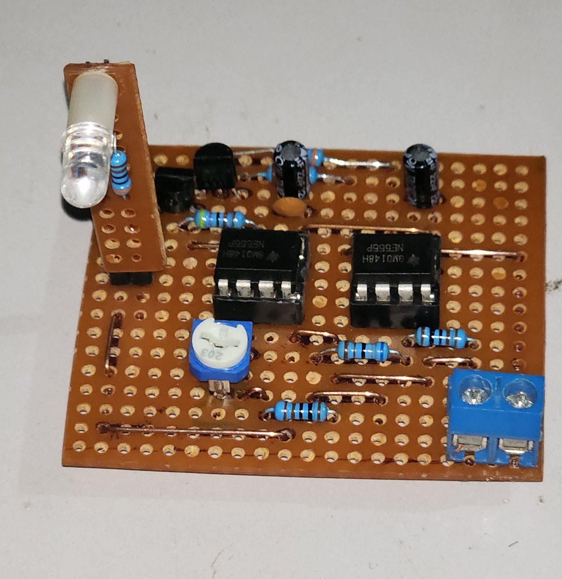
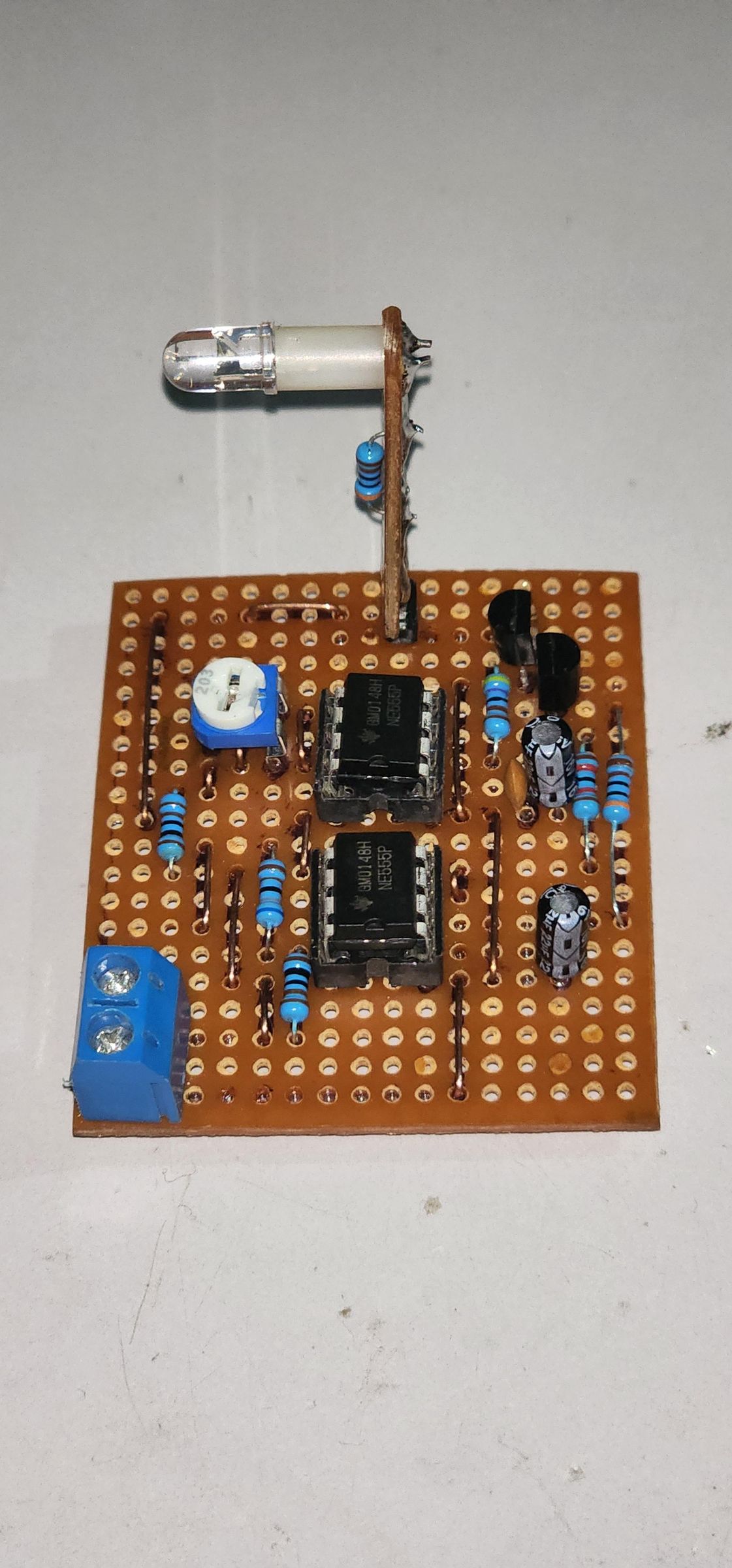
Components
- 2 × NE555 timer ICs
- 1 × IR LED
- 2 × 1 kΩ resistor
- 1 × 6.8 kΩ resistor
- 1 × 20kΩ resistor
- 1 × 10 µF capacitor
- 1 × 1 nF capacitor
- 1 × 4900 Ω, 1/2 W resistor
- 12 V DC power supply
- Breadboard and jumper wires
The complete circuit schematic and the final prototype are shown above.
Test the Circuit
1. Check the Oscillation Frequencies
Connect the outputs of the two oscillators to an oscilloscope and verify their frequencies:
- The first oscillator should generate approximately 10 Hz.
- The second oscillator should generate a carrier close to 38 kHz.
- Adjust the potentiometer of the second oscillator until the carrier frequency is precisely 38 kHz.
The 38 kHz carrier should appear as short bursts controlled by the first oscillator, with pauses between them.
2. Check the IR LEDs
Point the IR LEDs toward a smartphone camera. Most phone cameras can detect infrared light, allowing you to see the LEDs flashing when the emitter is operating.
The LEDs should appear to flash periodically, confirming that the 38 kHz carrier is being transmitted in bursts.
What's Next?
In the next Instructables, we will build different IR receiver circuits for specific applications, all using the same IR emitter developed in this project:
- Automatic Handwashing System — an IR beam barrier to detect the presence of a user's hands and activate the water flow automatically.
- Presence Detector — an IR-based system for detecting when an object or person crosses the beam.
- Remote-Controlled Lamp with a CD4017 — an IR receiver combined with a CD4017 to control a lamp remotely.
The advantage is that the same 38 kHz IR emitter can be reused in all these projects. Only the receiver and the processing circuit will