Build an IR Remote-Controlled Lamp With a CD4017
by DidierKabelu in Circuits > Electronics
395 Views, 4 Favorites, 0 Comments
Build an IR Remote-Controlled Lamp With a CD4017
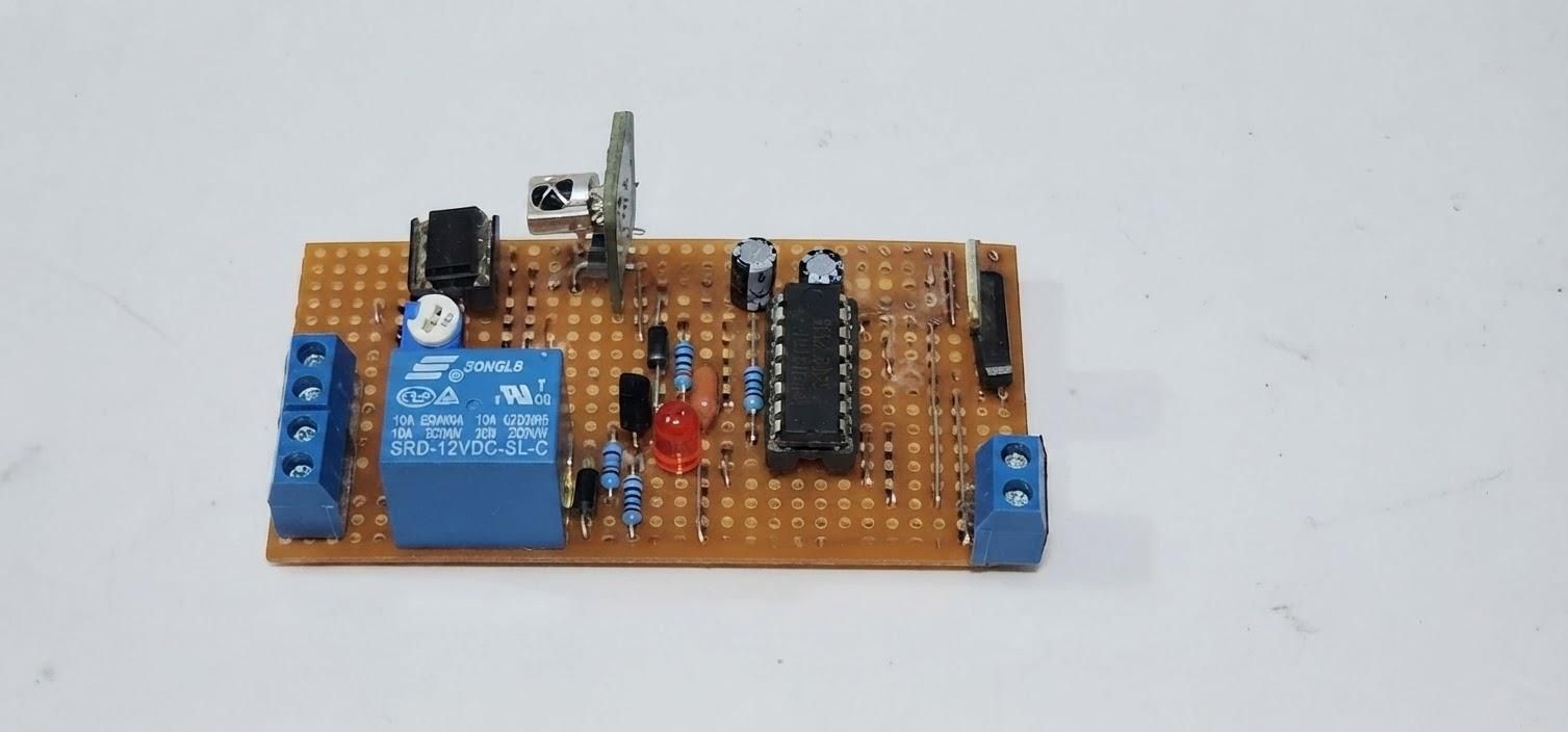
Have you ever turned off the light in your room and then realized that you still need to get out of bed to turn it back on? Sometimes, the simplest things can become surprisingly inconvenient.
What if you could control a 220 V lamp from a distance using a simple infrared remote control, without using a microcontroller?
In this project, we will build a simple IR remote-controlled lamp using a TSOP38 infrared receiver, a CD4017 decade counter, and a relay.
The system works with a simple push of a button on the remote: each press changes the state of the lamp. The same IR emitter developed in the previous Instructable can be used as the transmitter, making this project the next step in our IR system.
Beyond convenience, this approach can also be useful wherever we want to control an electrical load without having to physically operate its switch.
The circuit is intentionally built without a microcontroller, using simple and accessible electronic components to demonstrate how an infrared signal can be transformed into a practical control system.
What You’ll Learn
By the end of this tutorial, you will be able to:
- Understand how an IR receiver and a CD4017 can be used to control a lamp remotely.
- Configure a CD4017 as a toggle controller for a single lamp.
- Control a 220 V lamp through a relay.
Supplies
- 1 × CD4017
- 1 × TSOP38 IR receiver
- 1 × LED
- 1 × Electromagnetic relay
- 2 × 1N4007 diode
- 1 × 2N2222 transistor
- 1 × 100 nF capacitor
- 2 × 100 uF capacitor
- 2 × 220 uF capacitor
- 2× 10 kΩ resistor
- 1 × 20 kΩ potentiometer
- 1 × LM358
- 1 × 78L05
- 1 × Breadboard/ Prototyping Veroboard
- Jumper wires for the breadboard
Safety Warning — 220 V Mains Voltage
This project involves 220 V AC mains voltage, which can cause serious injury, electric shock, fire, or death.
Before building or modifying the circuit:
- Disconnect the circuit from the mains before making any changes or handling the wiring.
- Never touch exposed conductors while the circuit is connected to 220 V.
- Use properly insulated wires, connectors, and enclosures.
- Keep the low-voltage control circuit electrically isolated from the mains section.
- If you are not experienced with mains-voltage circuits, ask a qualified electrician or experienced technician for assistance.
Treat every 220 V connection as potentially dangerous, even when the circuit appears to be switched OFF.
Understand the Circuit
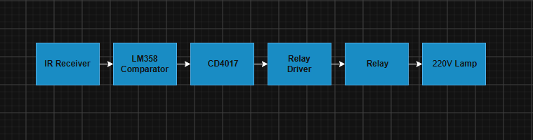
The system is built around five main blocks:
IR Receiver → Comparator → CD4017 → Relay Driver → Relay → 220VLamp
The IR receiver detects the 38 kHz infrared signal from the remote control and produces an electrical pulse at its output.
The LM358 comparator conditions this signal by comparing the receiver's output with a reference voltage, producing a clean logic-level pulse suitable for the CD4017.
The CD4017 acts as a decade counter and changes its output state each time it receives a clock pulse. This allows each press of the remote control to toggle the lamp between ON and OFF.
The relay driver, built around a 2N2222 transistor, provides the current required to energize the relay coil.
Finally, the relay switches the 220 V supply to the lamp, allowing the low-voltage control circuit to operate the AC load safely.
Downloads
Configure the CD4017
The CD4017 is a decade counter. Each valid clock pulse advances the HIGH state from one output to the next:
Q0 → Q1 → Q2 → Q3 → ... → Q9 → Q0
For the counter to advance:
- Clock Inhibit = LOW → clock pulses are accepted.
- Clock = rising edge → the counter advances on each rising edge.
- Master Reset = LOW → normal counting operation.
The Master Reset input is used to force the counter back to Q0. When it is HIGH, the counter immediately returns to Q0, regardless of the clock.
The Clock Inhibit input controls whether the counter accepts clock pulses. When HIGH, the counter stops counting.
In our circuit, we will use Q0, Q1, and Q2 to control the lamp and create the desired ON/OFF sequence.
Create the Lamp Control Sequence
We only use Q0, Q1, and Q2 of the CD4017 to create the ON/OFF sequence.
Clock Pulse Active Output Lamp
Initial state Q0 = HIGH ON
1st pulse → Clock Q0 → LOW, Q1 → HIGH OFF
2nd pulse → Clock Q1 → LOW, Q2 → HIGH OFF
Q2 → Master Reset Q2 → LOW, Q0 → HIGH ON
Q2 becomes HIGH, it activates the Master Reset, forcing the CD4017 back to Q0.
This creates a simple toggle function: each pulse of the remote changes the state of the lamp.
Condition the IR Receiver Signal
The TSOP38 output changes state when it detects the 38 kHz IR signal.
However, the receiver produces a rapidly changing signal during the IR burst. We only want the CD4017 to receive one clock pulse per IR command, not multiple pulses during the same burst.
To achieve this, we use a simple pulse-conditioning circuit:
- A 100 nF capacitor stores the pulse.
- A 10 kΩ resistor provides a discharge path to ground.
- A diode isolates the capacitor from the LM358 output and prevents this output from discharging the capacitor during the 38 kHz bursts.
This converts the fast activity at the IR receiver output into a single clean pulse suitable for the CD4017 Clock input.
Therefore, each detected IR command produces one clock pulse, which advances the CD4017 to the next output.
Build the Circuit
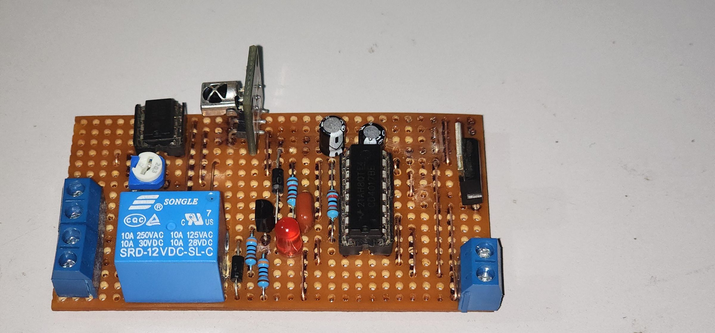
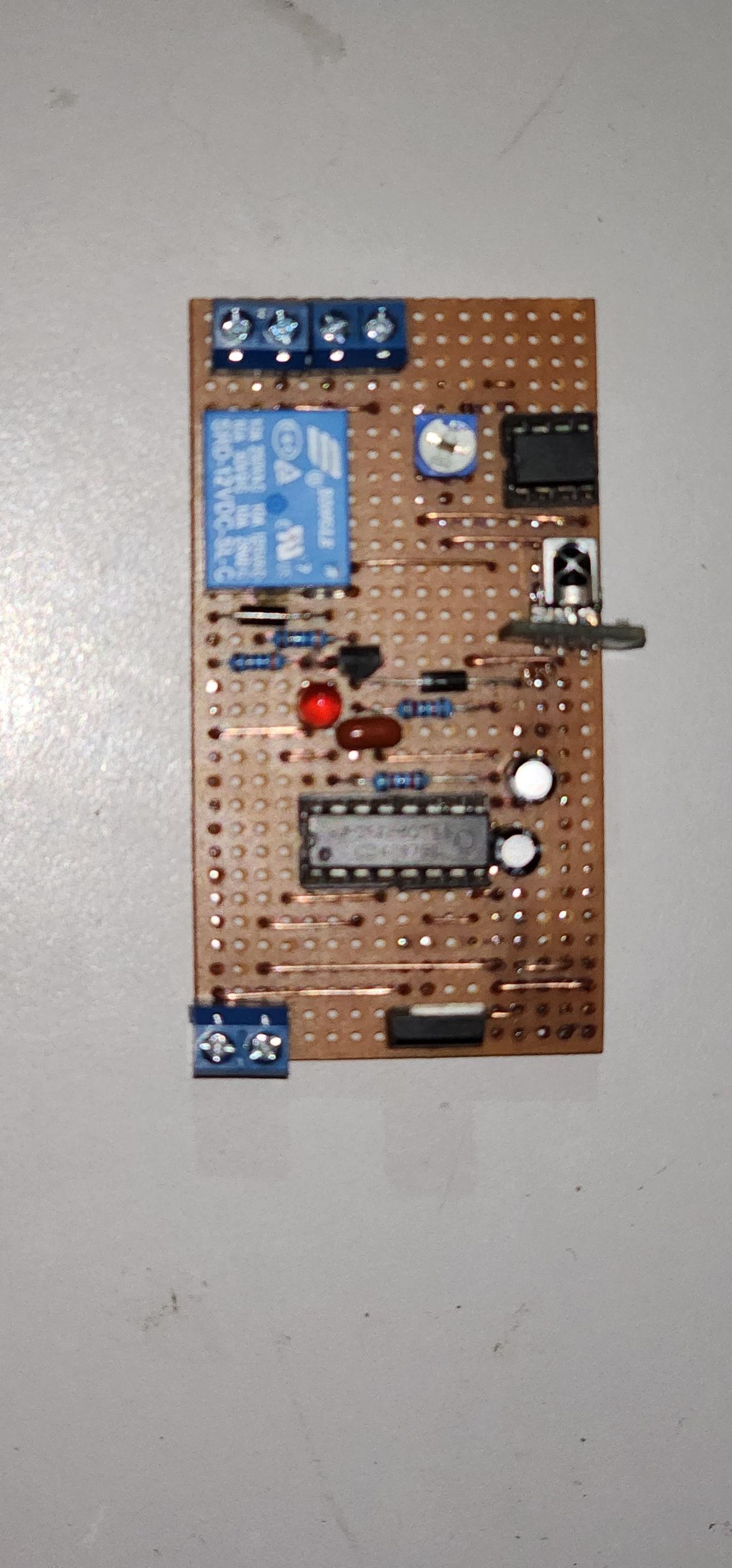
Now that we understand how each part of the system works, we can build the complete circuit.
Use the schematic below as a guide to connect:
- The TSOP38 IR receiver
- The pulse-conditioning circuit
- The CD4017
- The 2N2222 relay driver
- The 1N4007 protection diode
- The relay
- The LED indicator
The complete circuit and the finished prototype are shown above.
Test the Circuit
Before testing the remote control, first adjust the detection threshold of the LM358 comparator.
Use the potentiometer connected to the non-inverting input (+) of the comparator to set the reference voltage to approximately 3 V. Measure the voltage with a multimeter and adjust the trimmer until the desired threshold is reached.
Once the threshold is correctly adjusted, point the IR transmitter toward the TSOP38 receiver and press the remote-control button.
Each press should toggle the lamp:
- 1st press → Lamp OFF
- 2nd press → Lamp ON
Verify that the circuit responds reliably to one press at a time and that the relay switches correctly.
Safety: The relay contacts are connected to 220 V mains voltage. Disconnect the power before making any changes to the circuit, and use proper insulation and electrical safety practices.