Build an IoT Controlled Rover Using the AtumX Subo/ESP32-S3 and MQTT
by Ideas by Suyash Desai in Circuits > Robots
216 Views, 1 Favorites, 0 Comments
Build an IoT Controlled Rover Using the AtumX Subo/ESP32-S3 and MQTT
.jpeg)
.jpeg)
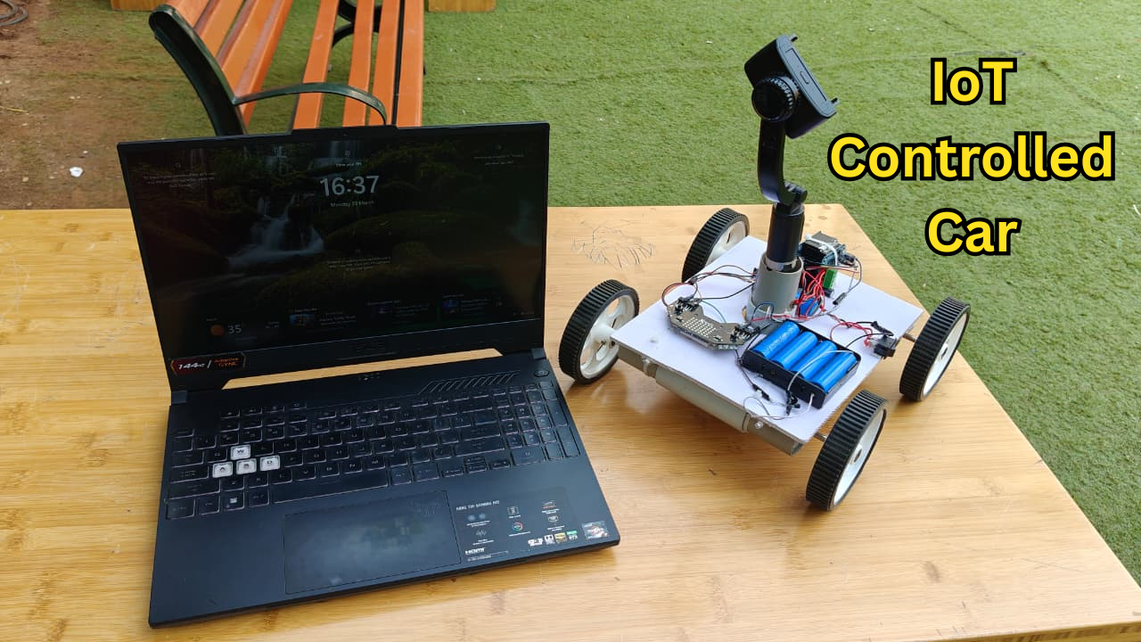
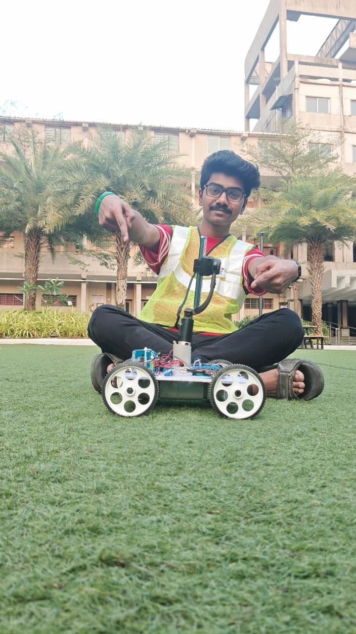
Imagine controlling your robotic rover from anywhere in the world using nothing more than a web browser and an internet connection. No Bluetooth range limitations, no dedicated mobile app—just open a webpage, connect to your MQTT broker, and you're ready to drive your robot in real time.
In this project, we'll build a cloud-controlled IoT rover using the AtumX Subo Super Board (ESP32-S3) and the MQTT protocol. The rover connects to Wi-Fi and securely communicates with a cloud MQTT broker, allowing you to control it from your laptop, tablet, or smartphone from virtually anywhere with internet access.
The project includes a custom-built web dashboard featuring keyboard controls (WASD), on-screen buttons for mobile devices, adjustable speed control, and real-time command transmission. To enhance user interaction, the onboard RGB LED matrix displays different colors based on the rover's movement, providing instant visual feedback.
Unlike conventional Bluetooth or RF-controlled robots that are limited to a few meters of range, this rover is controlled through the internet. Whether you're in another room, another city, or even another country, you can drive the rover as long as both the rover and your control device are connected to the internet.
This project serves as an excellent introduction to IoT, cloud robotics, MQTT communication, and remote device control while providing a solid platform for future upgrades such as robotic arms, FPV cameras, AI vision, obstacle avoidance, GPS navigation, and autonomous operation.
Supplies
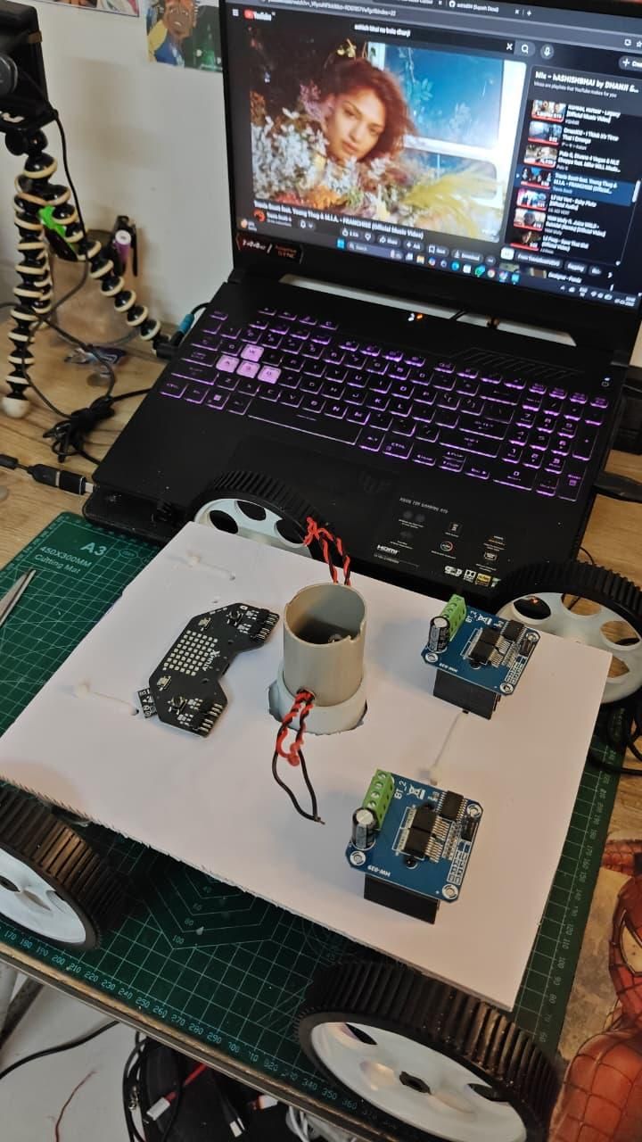
Electronics
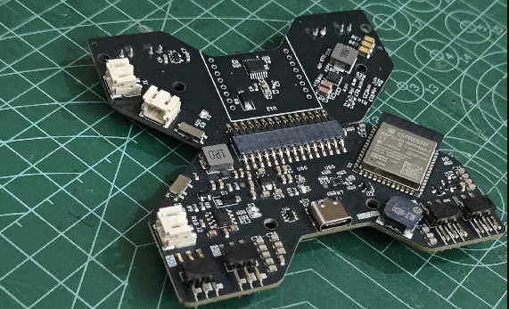
- AtumX Subo Super Board (ESP32-S3)
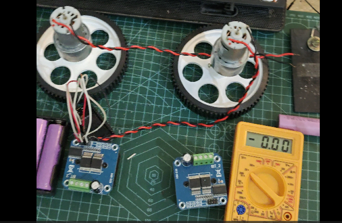
- 2 × BTS7960 Motor Drivers
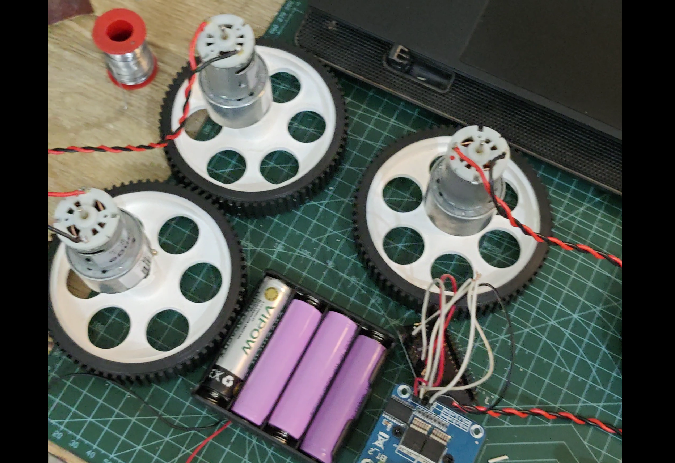
- 4 × DC Gear Motors(Johnson 12v HighTorque)
- Robot Chassis
- Li-ion Batteries(12v)
- Battery Holder
- Jumper Wires
- Wheels
- Castor Wheel
- USB Cable
Optional
- LEDs
- Active Buzzer
- Camera Module
- Ultrasonic Sensor
Software Required
- AtumX Trix IDE
- AtumX Subo Library
- Arduino IDE
- HiveMQ Cloud Account
- MQTT Explorer (optional)
- Modern Web Browser
Arduino Libraries
- WiFi
- WiFiClientSecure
- PubSubClient
- Subo Library
Assemble the Rover
.jpeg)
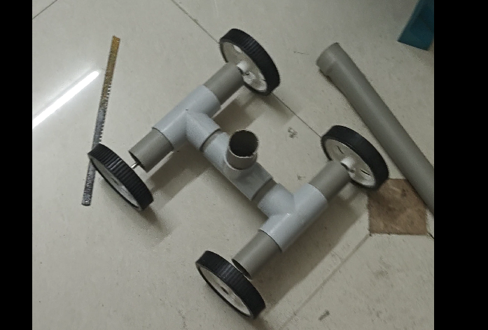
Build the robot chassis.
Install:
Make a chassis using PVC or 3D printer.
- Motors
- Wheels
- Battery
- Motor Drivers
- Subo Super Board
Ensure everything is securely mounted before wiring.
Wiring the BTS7960 Motor Drivers
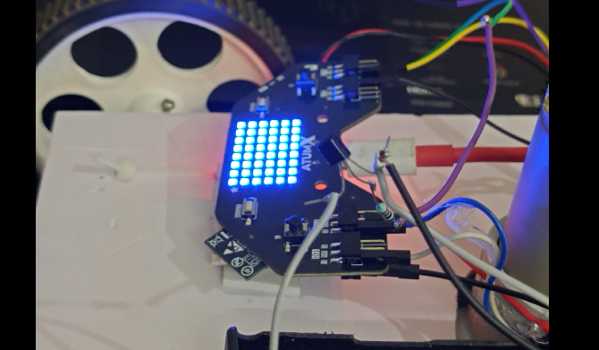
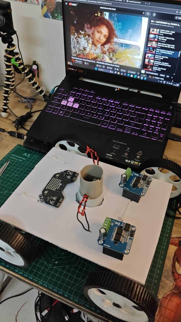
In this project, two BTS7960 High-Power Motor Drivers are used to independently control the left and right DC motors. Each driver requires two PWM signals from the AtumX Subo/ESP32 to control the motor's speed and direction.
Left BTS7960
- RPWM → GPIO 4
- LPWM → GPIO 39
- R_EN → 5V
- L_EN → 5V
- VCC → 5V
- GND → GND (Common Ground)
- B+ → Battery Positive (+)
- B− → Battery Negative (−)
- M+ → Left Motor Terminal
- M− → Left Motor Terminal
Right BTS7960
- RPWM → GPIO 13
- LPWM → GPIO 38
- R_EN → 5V
- L_EN → 5V
- VCC → 5V
- GND → GND (Common Ground)
- B+ → Battery Positive (+)
- B− → Battery Negative (−)
- M+ → Right Motor Terminal
- M− → Right Motor Terminal
Important: Ensure the Subo board GND, both BTS7960 GND pins, and the battery negative terminal are connected together (common ground). If a motor spins in the opposite direction, simply swap its M+ and M− connections.
Install Required Libraries
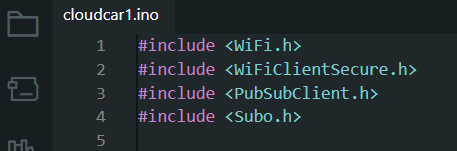
Install the following libraries through the Arduino Library Manager.
- PubSubClient
- WiFi
- WiFiClientSecure
Also install the AtumX Subo library provided by AtumX.
Create Your HiveMQ Cloud Broker
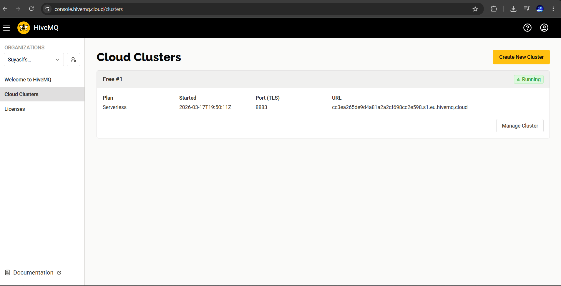
- Create a free HiveMQ Cloud account.
- Create a new MQTT Cluster.
- Wait until the cluster is running.
- Create MQTT credentials.
- Copy:
- Server Address
- Port (8883)
- Username
- Password
These credentials will be used in both the Arduino sketch and the web dashboard.
Why MQTT?
With MQTT: https://www.hivemq.com/mqtt/
- The rover can be controlled from anywhere in the world.
- Multiple devices can communicate through the same broker.
- Communication is encrypted using TLS.
- Very low latency makes driving smooth and responsive.
As long as both the rover and your control device are connected to the internet, distance is no longer a limitation.
Upload the Firmware
Open the Arduino sketch or Trix App.
Code & Details: https://github.com/astrix884/Cloud-Controlled-IoT-Rover.git
Replace:
- Wi-Fi SSID
- Wi-Fi Password
- MQTT Server
- MQTT Username
- MQTT Password
Upload the program.
Open the Serial Monitor.
You should see
Create the Web Dashboard
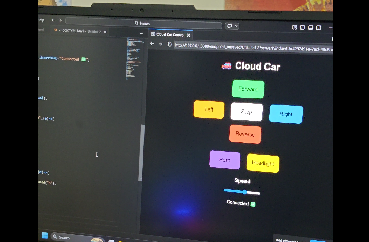
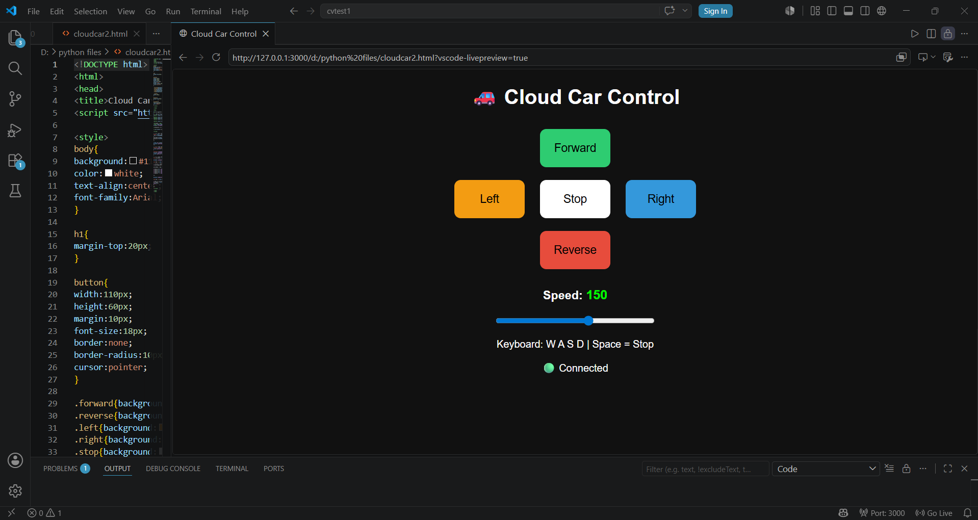
The dashboard is built using
- HTML
- CSS
- JavaScript
- MQTT.js
Features include:
- WASD Control
- Mobile Buttons
- Speed Slider
- Secure WebSocket MQTT Connection
Save the webpage and simply open it in any modern browser.
No installation is required. You can deploy it on netlify.
Drive the Rover
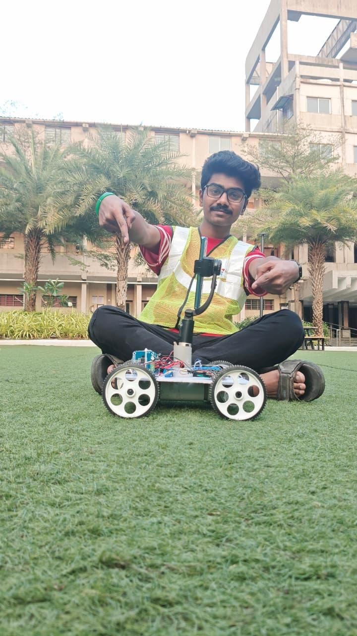
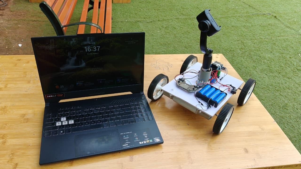
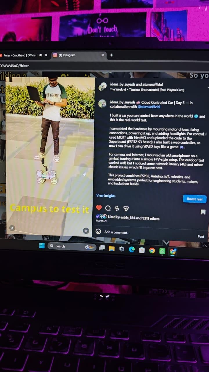
.jpeg)
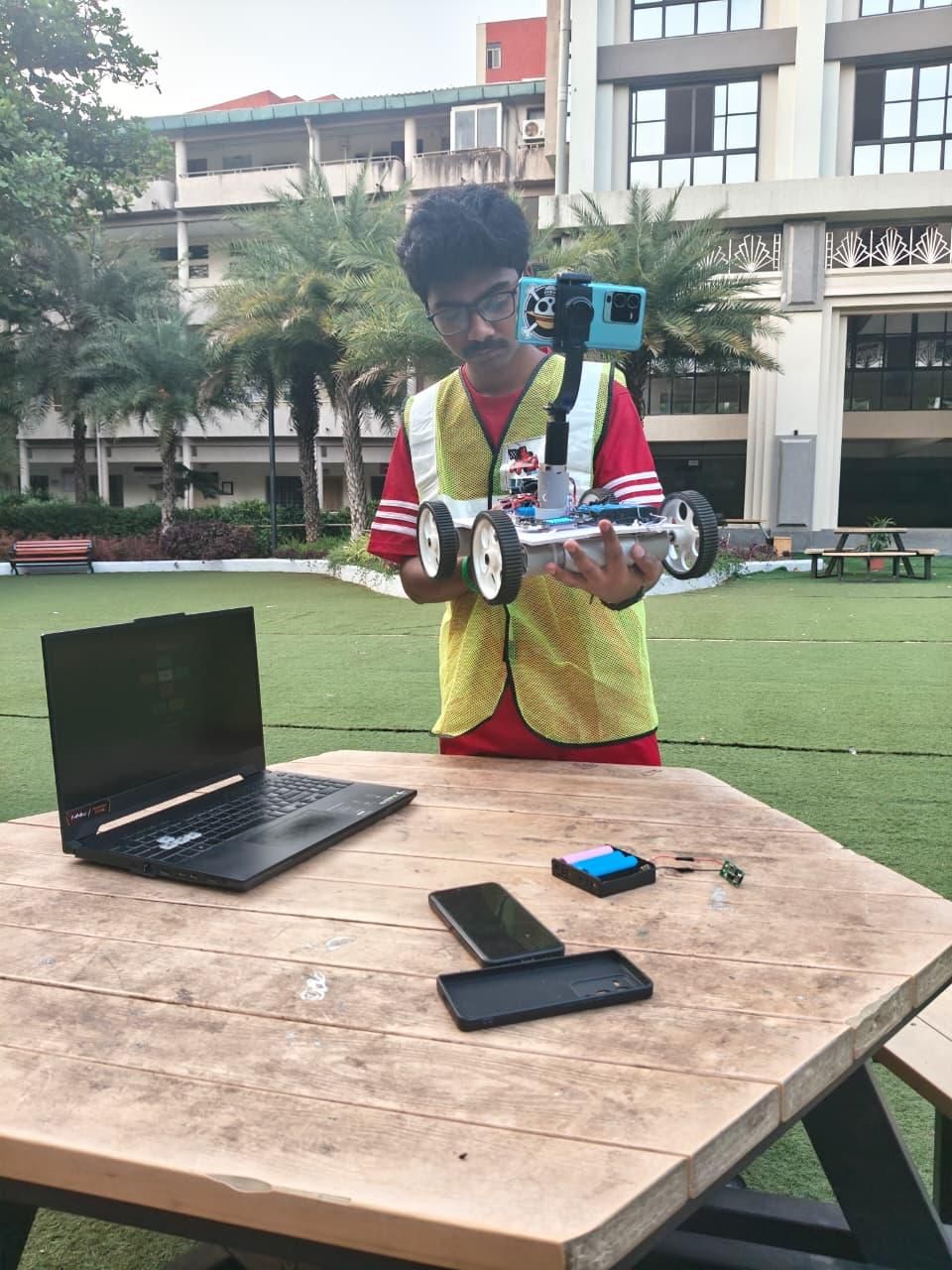
Watch Full Build Series On Instagram: Full Reel Series
Once both devices are connected to the internet:
Open the dashboard.
Use:
Adjust the speed using the slider.
The rover should respond almost instantly.
Conclusion
In this tutorial, we built a cloud-controlled IoT rover using the AtumX Subo Super Board and MQTT. By combining an ESP32-S3, secure cloud communication, and a browser-based dashboard, we created a responsive robot that can be driven from virtually anywhere with an internet connection.
This project is a great introduction to cloud robotics and provides a flexible platform for adding advanced features such as AI, computer vision, automation, and autonomous navigation. Whether you're a student, hobbyist, or maker, it offers a practical way to explore the power of IoT in robotics.
Happy building, and if you enjoyed this project, consider sharing your own improvements or adaptations! 🚀