Building a Budget Friendly Simulator Chair
by burairhaidar1 in Workshop > Science
938 Views, 0 Favorites, 0 Comments
Building a Budget Friendly Simulator Chair
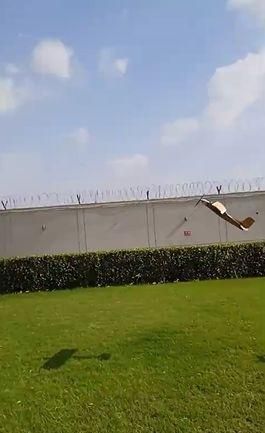
Ever watched an RC car tear up a track or an RC plane bank through the clouds and thought, “Man, it would be insane to actually feel what it’s like to sit inside that thing?”
You could buy a multi-thousand-dollar commercial motion rig and try to hack together an interface for RC telemetry, but unless you’ve got endless cash to burn, that’s way out of reach for most of us.
Supplies
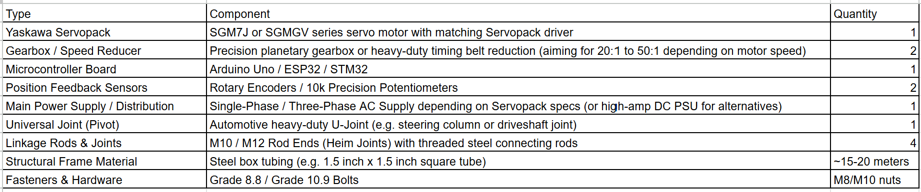
Depending on where you are, some of these exact components might be tricky to source off the shelf, so feel free to pivot to common alternatives. For instance, if you don't have Yaskawa Servopacks, you can swap in a NEMA 23 or NEMA 34 stepper motor paired with a high-reduction gearbox—just make sure your final setup delivers around 20–30 Nm of output torque. Don't feel like fabricating a frame from scratch? Repurposing an old sturdy stool frame works great as a base.
We strongly encourage you to improvise and adapt with whatever materials you have in your workshop. After all, working through constraints with what's in front of you is what engineering is all about!
(Note: For the walkthrough in this guide, we’ll be focusing on the Servopack and motor configuration.)
Building the Base
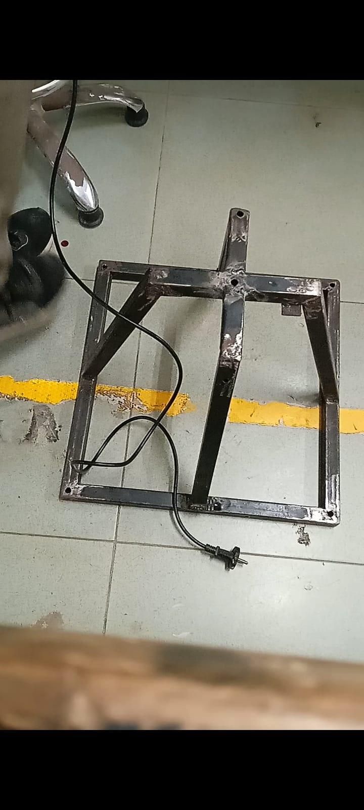

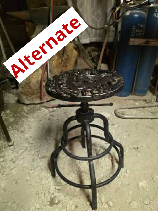
Your base needs to be rock-solid and stable enough to comfortably support your weight plus an extra 50 kg of dynamic motion and hardware.
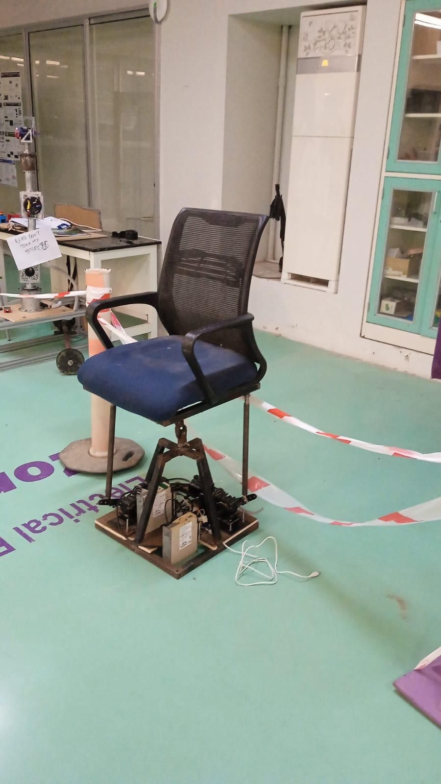
I welded mine together out of square steel tubing since I had a welder on hand, but you don't need a full fab shop to make this work. A heavy-duty metal stool can work just as well. Just make sure whatever structure you choose has a clear center mounting point where we can attach the universal joint for the upper chair platform.
Attaching the Mount
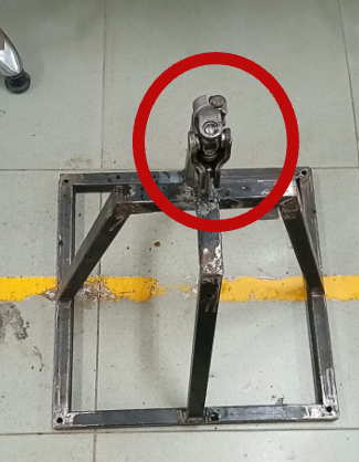
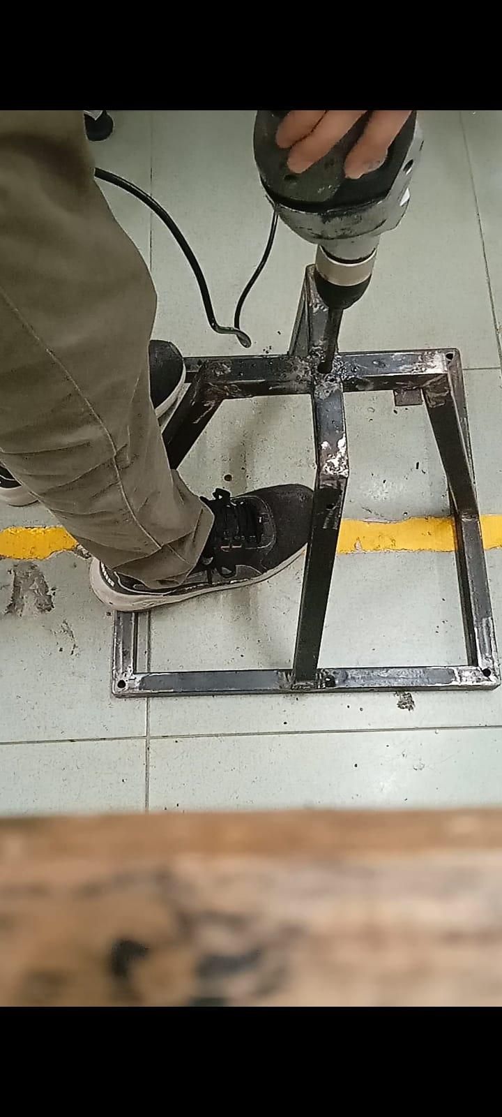
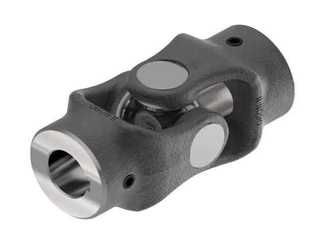
Next, mount a heavy-duty universal joint (U-joint) directly to the center of your base.
Because our motors are built to handle motion rather than bearing the entire static load, the U-joint acts as the central load-bearing pivot. It takes off all the structural weight of the chair and user while allowing smooth, full-range movement in both pitch and roll. Your top seat frame will bolt directly onto the top flange of this joint.
Connecting a Frame to the Base
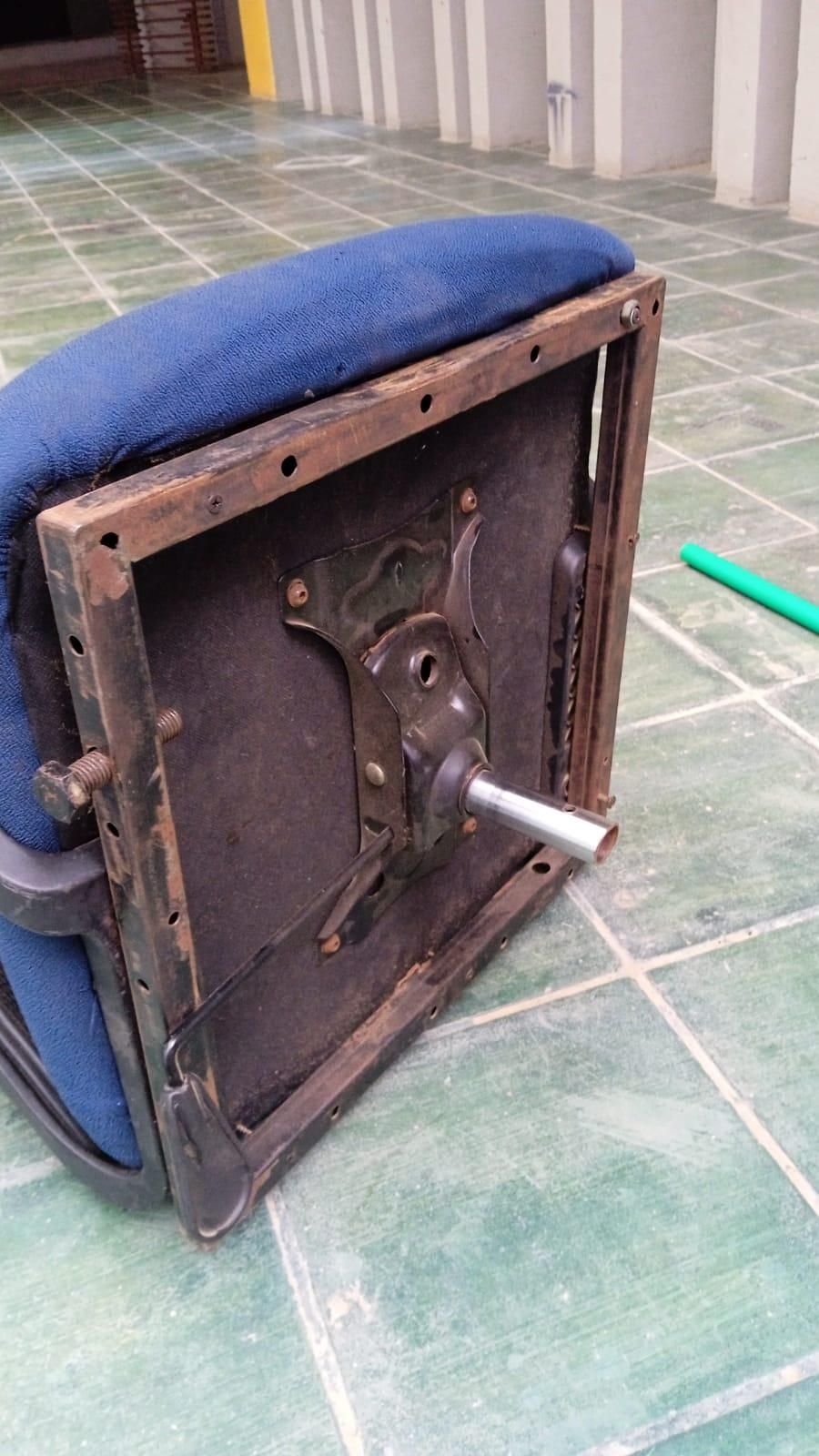
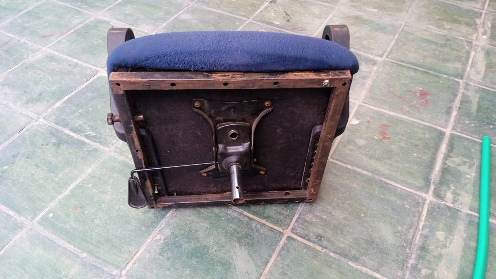
Now it's time to source the seat itself. I repurposed an old office chair by sawing off its rolling base, but you can use whatever seat you have available.
Ideally, pick a chair that connects to its base via a single center pedestal or cylinder. Once you cut off the base and cylinder stem, you'll need to attach a flat metal plate or square tube frame to the underside of the chair seat. Since most office chair seat bases are reinforced plywood, screwing or bolting your custom metal mounting plate directly to the bottom is quick and straightforward.
Attaching the Chair to the U Joint
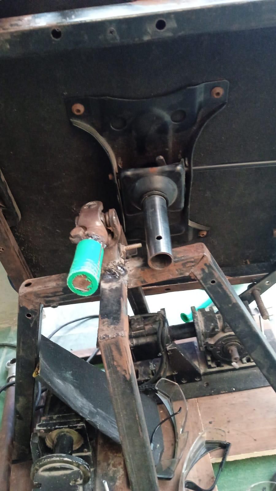
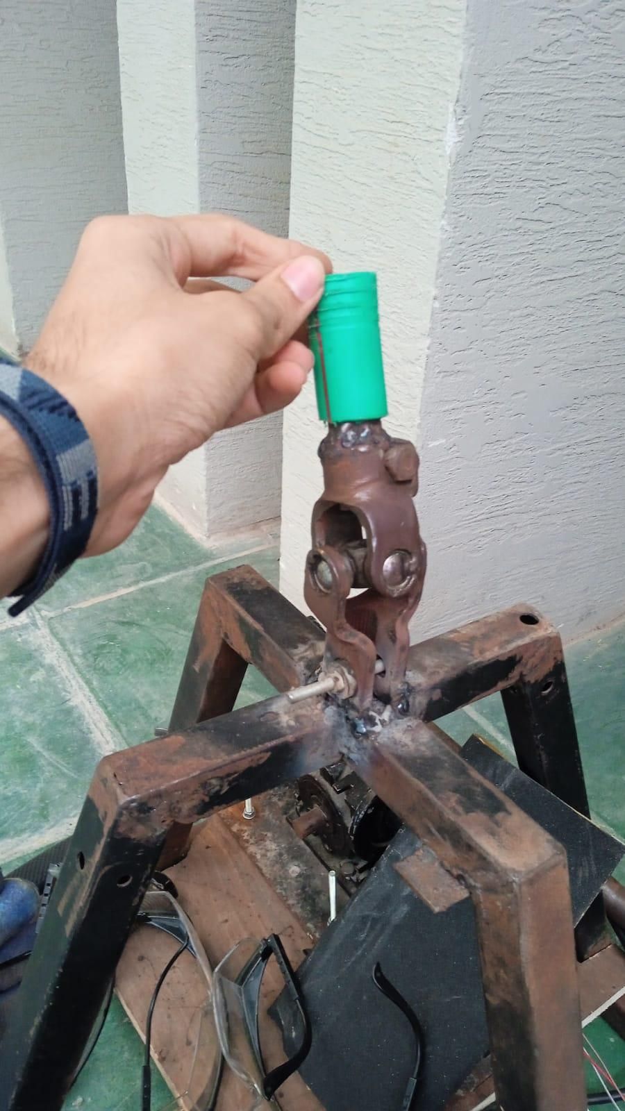
Now it's time to join the chair assembly to the central universal joint.
The mounting tube on the bottom of your chair needs to slide cleanly over (or inside) the top shaft of the U-joint. If there's any play or slop between the two cylinders, fix it by adding a piece of steel sleeve or pipe to get a tight, snug fit.
To keep the chair from spinning independently on the shaft:
- Option A (Welding): Weld the two concentric tubes together around the seam for a permanent connection.
- Option B (Bolting): Drill a hole straight through both overlapping tubes and secure them using an M8 or larger grade 8.8 bolt with a locking nut.
Electronics Setup & Servopack Configuration
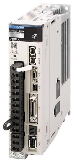
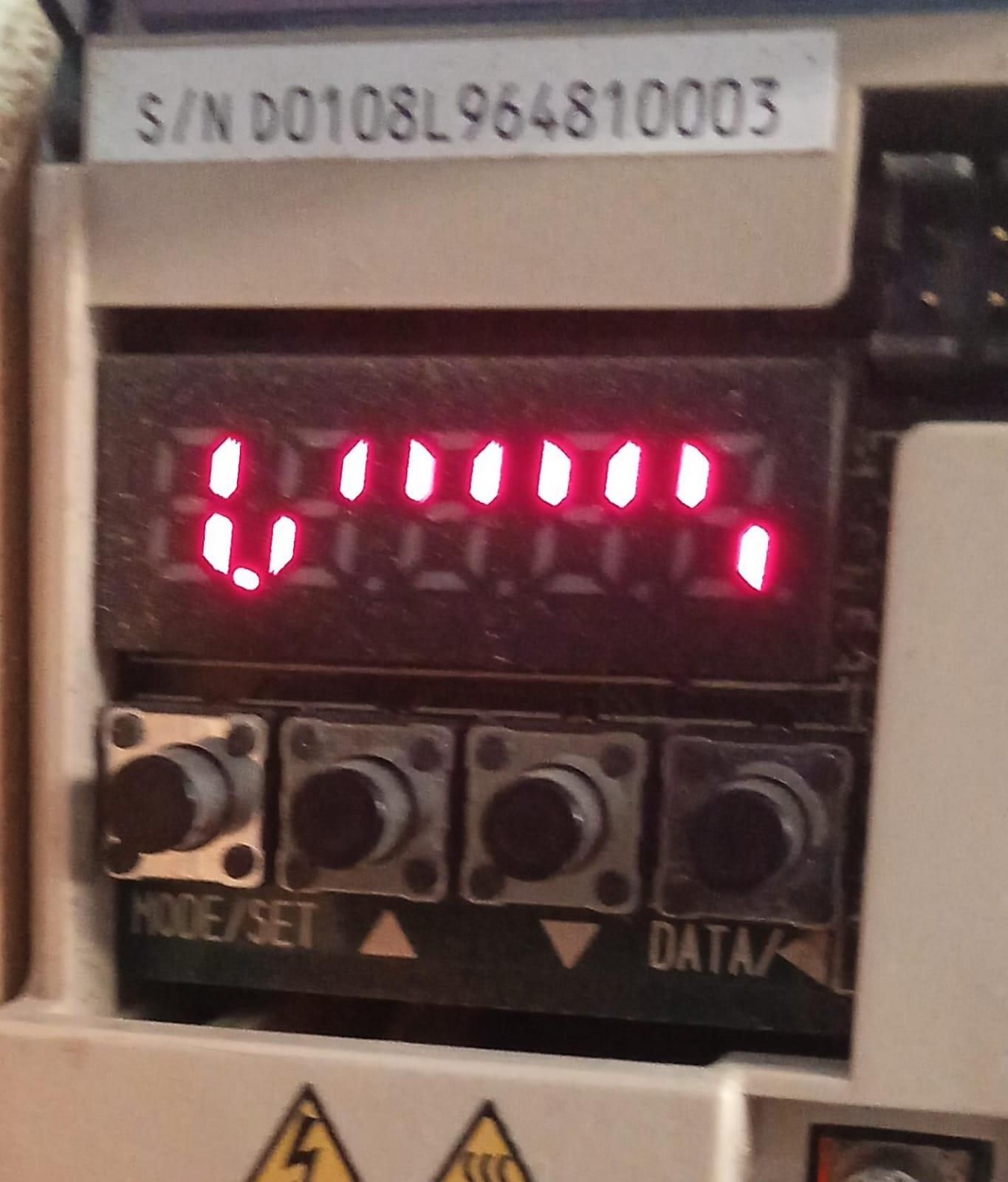

For the drive system, we’re using high-torque AC servo motors paired with matching Yaskawa Servopacks. These motors come with pre-attached gearboxes to bring the final output torque into our target range.
Because industrial AC servos require specialized signal translation, the Servopack acts as the main bridge between our control logic and the motor hardware. While we won’t dive deep into every individual drive parameter in this guide, you can configure all internal parameters directly using the 4-button interface on the front panel of the Servopack.
(Note: If you are replicating this exact setup, I’ve linked a Google Sheet containing the full parameter configuration table in Step 1 to get your drives running straight away.)
If you aren't using industrial AC servos, you can easily substitute them with high-torque stepper motors such as a NEMA 23 or NEMA 34 paired with high-reduction planetary gearboxes.
Just double-check your gear ratios so your final crank output delivers around 20–30 Nm of torque. Configuring stepper drivers (like a DM556 or TB6600) with microstepping is super common for motion rigs, and there are tons of great step-by-step video tutorials online that walk through wiring and tuning NEMA steppers for DIY simulators.
Mounting the Actuators & Linkage Assembly
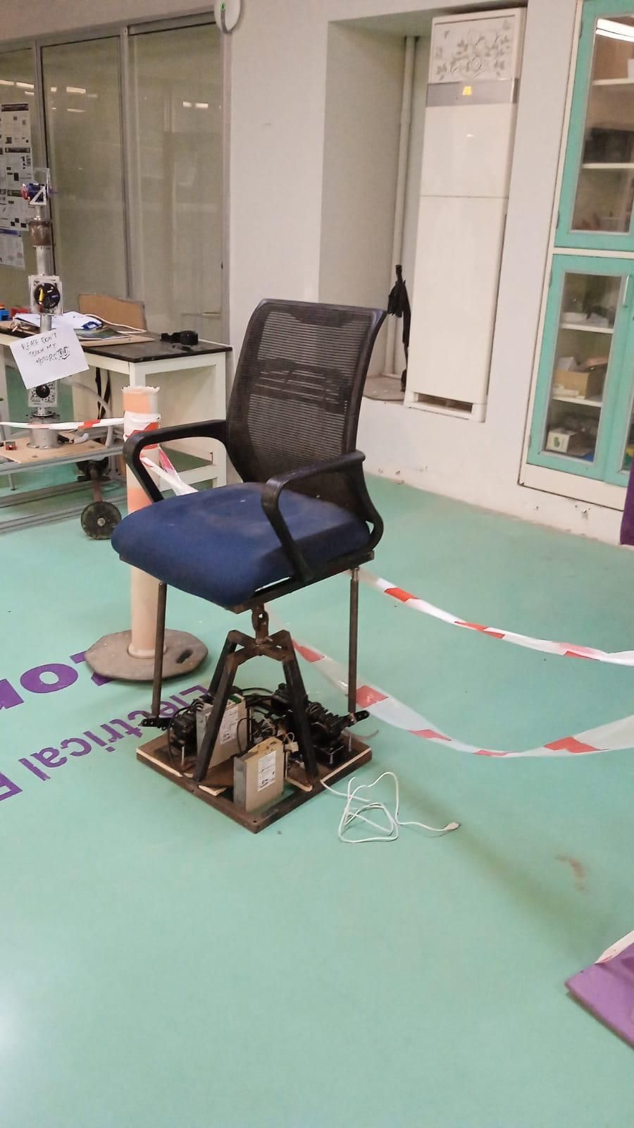
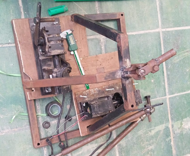
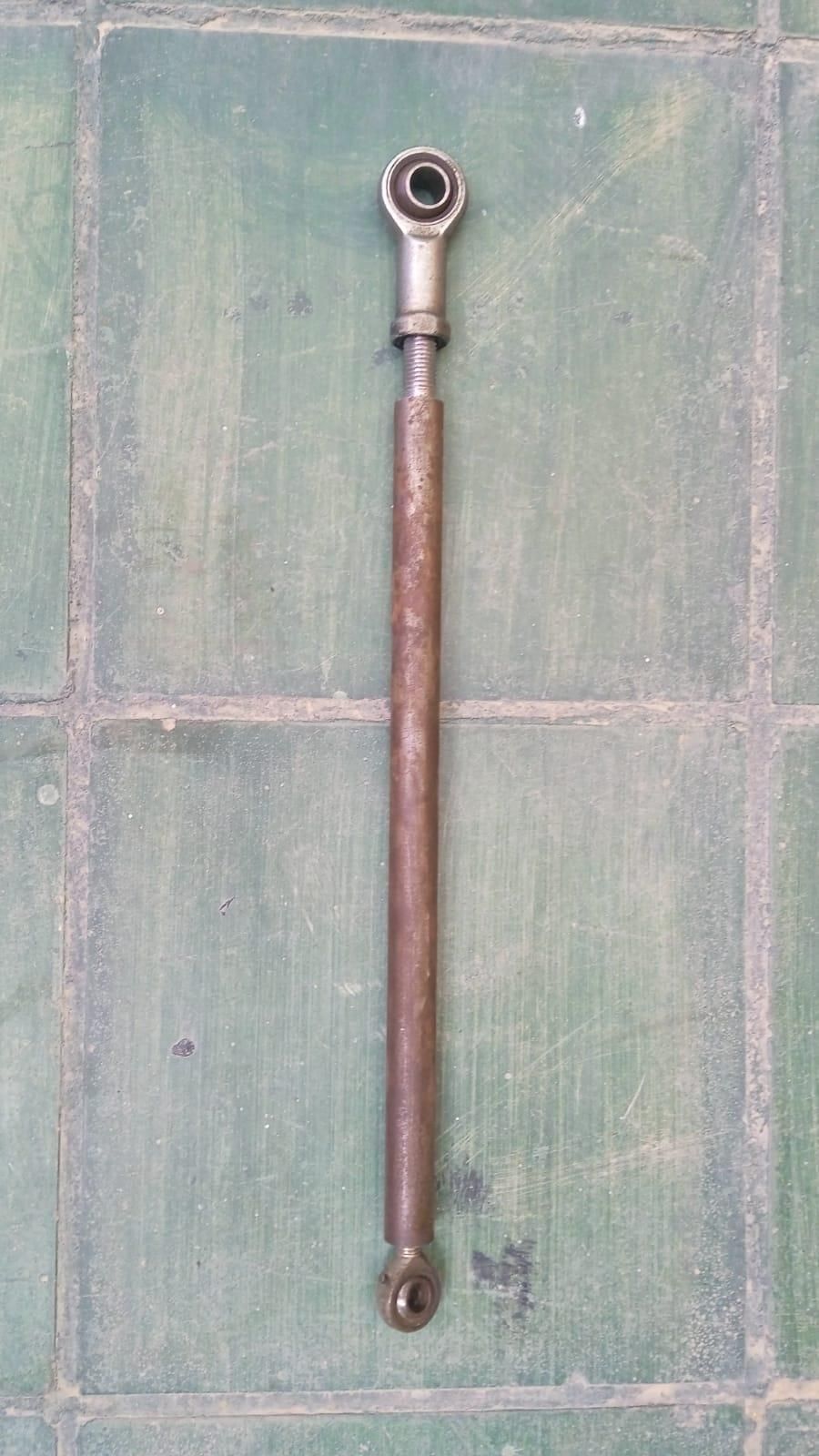
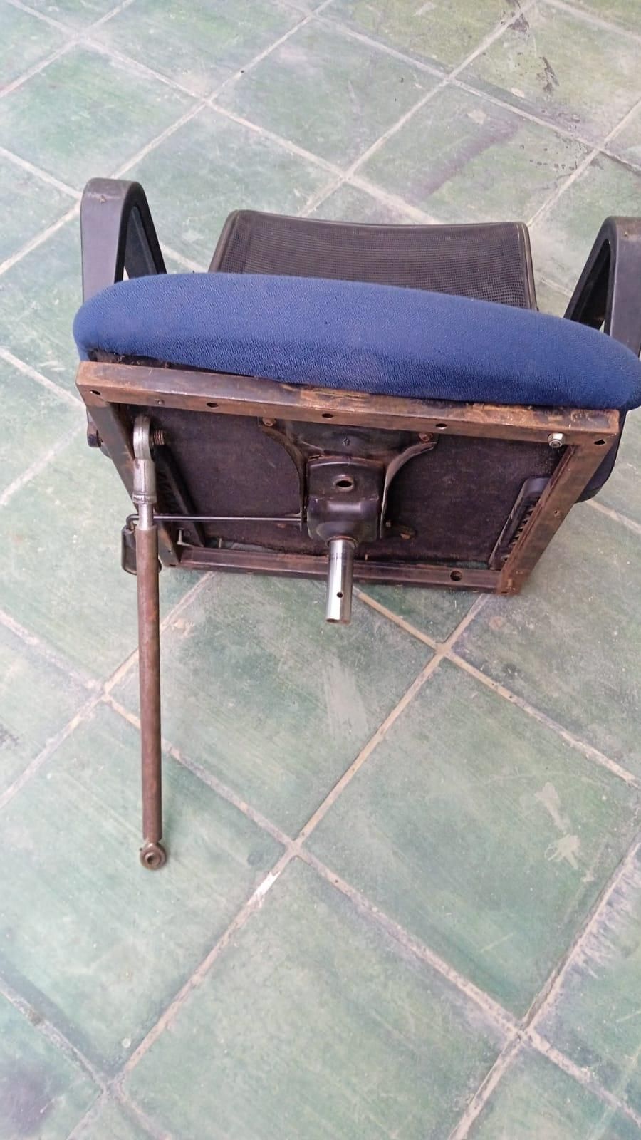
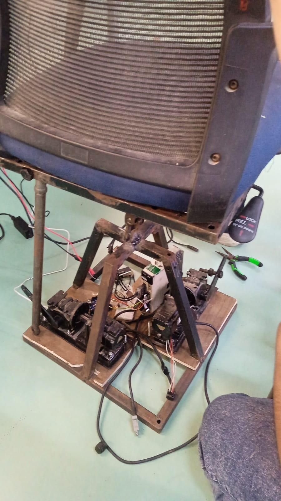
Step 11: Mounting the Actuators & Linkage Assembly
Mounting the drive motors to the lower frame base is straightforward. Secure each motor to the base frame using M5 or larger high-grade bolts.
- Actuator Positioning: Position one motor directly aligned under one side of the upper chair frame, and place the second motor under an adjacent side (at a $90^\circ$ angle). For my rig, I mounted one motor along the back side (for pitch) and the other along the left side (for roll).
- Linkage Connection: Attach a rigid steel servo arm/crank to each motor shaft. Connect a threaded push rod from the end of the crank arm up to the corresponding edge of the upper chair base.
- Joints & Degrees of Freedom: Use ball joints or Heim joints (rod ends) at both ends of each push rod. Standard rigid hinges will bind—ball joints are crucial because they provide the multi-axis freedom required when pitch and roll move simultaneously.
(Refer to the build photos for exact alignment and crank arm angles.)
Conclusion & Future Upgrades!!
And just like that, you have a fully functional, custom-built motion simulator!
Once you have this core motion base built and calibrated, the possibilities are practically endless. You can interface it with open-source PC flight simulators (using SimTools or FlyPT Mover) for realistic flight physics, or take your RC setup to the next level:
- FPV Head Tracking: Mount a pan-and-tilt FPV camera inside your RC vehicle paired with FPV goggles. When you turn your head, the camera looks around inside the cockpit while the chair mimics every tilt and turn.
- Software Telemetry Integration: Map game telemetry directly from titles like Assetto Corsa, MSFS 2020, or DCS World to experience full motion immersion.
The beauty of DIY engineering is that you now have an open, customizable platform to modify however you see fit. Build it, tune it, and make it your own!