Building a Minimalist STM32U0 Board for Learning Register-Level Embedded Programming
by MAKAO in Circuits > Electronics
104 Views, 0 Favorites, 0 Comments
Building a Minimalist STM32U0 Board for Learning Register-Level Embedded Programming
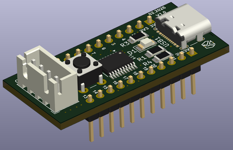
Not every dev board needs to be a Swiss Army knife. Sometimes the most useful thing you can build is a board with almost nothing on it — just enough to power up, flash firmware, and blink an LED — so that what happens next is entirely up to the person writing the code, not the board's peripheral list.
That's the idea behind this board. At its center sits an STM32U031F8P6 in a 20-pin TSSOP package: an Arm Cortex-M0+ core with no DMA-heavy peripheral sprawl to get lost in, no math coprocessors to learn before you can blink an LED, just a clean, small register map that's genuinely approachable for someone learning to program a microcontroller directly against its datasheet instead of through several layers of abstraction. A single USB-C connector supplies power only, a 3.3V regulator handles the rest, and programming happens exclusively through SWD — no UART bridge, no bootloader shortcuts, just a debug probe and the chip.
In this Instructable, I'll go through why this particular MCU is a good fit for that goal, the reasoning behind stripping the board down to power + SWD only, and the small but important details (like USB-C power negotiation) that are easy to get wrong on a "just power it" board like this one.
Why Build a Board This Minimal?
There's no shortage of beginner-friendly boards already — Arduino Uno, Raspberry Pi Pico, Blue Pill — so it's worth being clear about what gap this one is trying to fill.
Arduino Uno/Nano gives beginners an unmatched library ecosystem, but that's exactly the problem for someone who wants to learn what's actually happening at the hardware level: digitalWrite() hides the GPIO register writes underneath it almost completely. Great for building projects fast, less great for understanding why a pin toggles.
Raspberry Pi Pico (RP2040) is a fantastic and cheap board, but it's a dual-core Cortex-M0+ with a fairly large, PIO-heavy peripheral set (the programmable I/O blocks alone are a small learning project in themselves) — arguably more surface area than someone wants when the goal is "understand a basic UART or timer peripheral from the reference manual up."
STM32 Blue Pill (F103) is a classic choice for register-level learning and it's a fair comparison point, but the F103's Cortex-M3 core and its more complex peripheral set (multiple timer types, richer clock tree, remap registers) mean there's simply more to read before writing your first few lines that touch hardware directly.
This board's answer is to lean into the STM32U0 series specifically because it's one of ST's newer entry-level families — Cortex-M0+, single bus matrix, a comparatively short reference manual — while still being a real, current-generation part with modern low-power modes worth learning about, rather than a decade-old chip kept alive purely by community inertia.
The honest trade-off: this simplicity is also a ceiling. There's no hardware floating-point, no advanced timer with complementary PWM outputs, no CORDIC or FMAC, and a comparatively small 64 KB flash / 12 KB SRAM budget. This is not a board for motor control or DSP projects — it's a board for the person who wants to genuinely understand GPIO, timers, interrupts, and low-power modes before moving on to something more capable.
The Brain: STM32U031F8P6
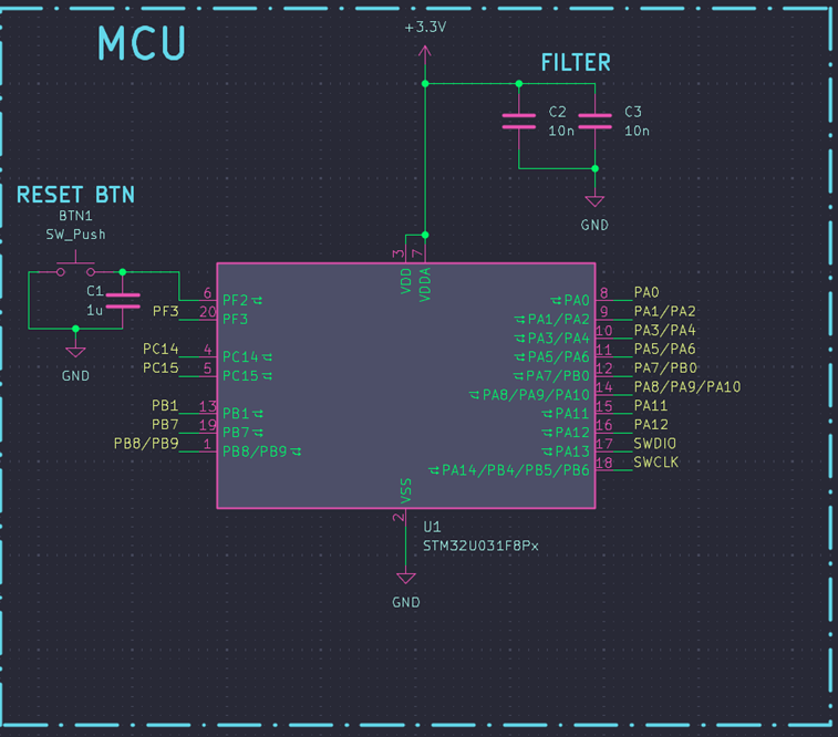
The STM32U031 is part of ST's STM32U0 series, positioned as an ultra-low-power entry-level line — effectively a modern, low-power-focused successor to the older F0/L0 chips, rather than a scaled-down version of the performance-oriented G4/H7 lines.
Key specs relevant to this board's purpose:
- Arm Cortex-M0+ core, running up to 56 MHz — a simpler pipeline than Cortex-M3/M4, with a smaller and more approachable instruction set, which matters directly for someone reading disassembly or writing register-level startup code for the first time.
- Up to 64 KB single-bank flash and 12 KB SRAM — small enough to actually read a full memory map without feeling lost, though it does cap what kind of projects fit (no space for large buffers, string-heavy code, or bulky libraries).
- 1 KB instruction cache allowing zero-wait-state execution from flash — a nice, free performance detail worth explaining to someone learning about flash access latency for the first time.
- Communication peripherals: three I2Cs, two SPIs, four USARTs, and two low-power UARTs — a genuinely generous peripheral count for a 20-pin chip, giving plenty of room for follow-up projects (I2C sensor reading, SPI displays, a from-scratch UART driver) without needing a different board.
- True random number generator — an unusual and welcome inclusion at this price/complexity point, useful for teaching cryptography basics or just generating non-repeating test data.
- Independent analog supply pin and VBAT input for RTC/backup register retention — small but real ultra-low-power design details that are worth pointing out even if this particular board doesn't populate a coin-cell holder for VBAT.
- Low-power modes (Stop, Standby/Shutdown-class modes) typical of the U0 series — genuinely useful material to teach, though this board's design (USB-C-only power, no battery holder) doesn't really let a reader measure those savings without extra hardware. Worth flagging as a natural "next step" project: adding a battery clip and a way to measure supply current would turn this into a proper low-power-mode teaching board rather than just a chip that's capable of it on paper.
Where this MCU falls short compared to a "bigger" STM32: no hardware multiply-accumulate blocks, no advanced-control timers with dead-time insertion (so no complementary PWM for motor/power projects), and a peripheral clock tree that, while simpler than a G4's, is still complex enough that a first-time reader will want the reference manual open next to the code editor rather than trying to guess register bit positions from memory.
Bottom line: for a board whose whole purpose is "read the reference manual, touch the registers yourself," the U031 hits a good spot — modern enough to be worth learning, simple enough that the learning curve is about the peripherals themselves and not about wading through unrelated complexity first.
Power: USB-C for Power Only
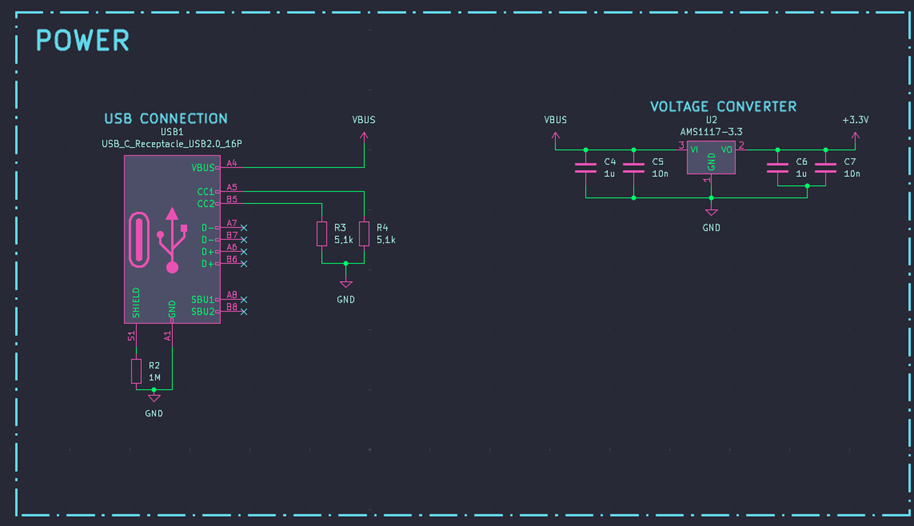
The USB-C connector on this board has exactly one job: deliver 5V in. There's no data connection to the MCU at all — no D+/D- routed anywhere, since the U0 series doesn't include a USB peripheral to connect them to in the first place. From there, a linear regulator drops 5V down to the 3.3V rail the MCU and everything else runs on, the same basic topology as a typical USB-powered 3.3V board.
Why "power only" is a perfectly reasonable design choice here, rather than a missing feature:
- It matches the MCU honestly — there's no native USB peripheral on this chip to wire up, so pretending otherwise would just be a fake connector.
- It keeps the board's story simple for a learning-focused product: power comes in one well-labeled port, programming happens over a separate, clearly different connector (SWD). No ambiguity about "why doesn't this port do anything when I plug it into my laptop."
- Fewer traces and no ESD protection needed for a data line that doesn't exist — smaller BOM, smaller board.
The detail that's easy to miss on a "power only" USB-C connector, and worth double-checking on this design: USB-C, unlike USB-A/micro-USB, doesn't supply power just because 5V is present on the VBUS pin. A USB-C source (a modern charger, a laptop port, a power bank) is expected to see a pull-down resistor on the cable's CC1 and CC2 lines before it will enable VBUS output at all — this is the basic USB-C power-role detection mechanism, separate entirely from USB data or USB-PD negotiation. The standard, cable-orientation-independent way to do this on a fixed-current sink (i.e., "just give me 5V, up to 500 mA or so") is to place a 5.1 kΩ pull-down resistor on both CC1 and CC2 to ground.
If only one CC line has a pull-down: the board will still work correctly when the USB-C plug happens to be inserted in the orientation that lines up with the populated CC line, and simply fail to receive any power (or receive it inconsistently across different chargers) when flipped, since USB-C cables are reversible by design and the host can't tell which orientation was used without a CC signal on the corresponding line. This is a classic and very common "power only" USB-C layout mistake, precisely because it's easy to test successfully on the bench (you plug it in the "right" way without thinking about it) and then fail intermittently for an end user.
On the regulator itself: assuming the same 5V→3.3V linear regulator topology used on other boards in this lineup (an AMS1117-3.3-class LDO) — simple, cheap, no switching noise, more than enough current headroom for a single low-power Cortex-M0+ chip that draws only a few mA in Run mode. The same caveats apply as always with this class of part: counterfeit/out-of-spec AMS1117 chips are common from untraceable sources, and 100% of the voltage drop becomes heat rather than useful output — a complete non-issue at these current levels, but worth knowing if this board ever gets adapted to power anything beyond the MCU itself.
Debug Interface: SWD Only, No UART Bridge
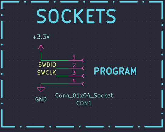
Unlike boards that pair an onboard USB-UART bridge with SWD, this one skips the bridge chip entirely. Programming and debugging both go exclusively through the SWD connector.
Why this is the right call for this specific board, rather than a missing convenience:
- It matches the "read the registers, understand the hardware" teaching goal directly — SWD-based debugging (breakpoints, register/memory inspection, single-stepping) is arguably a better learning tool than a UART print statement anyway, since it lets a learner watch peripheral registers change in real time rather than inferring behavior from printed text.
- One fewer chip, one fewer driver dependency, one fewer thing to explain before a first-time user can get code running. For a board whose target audience is explicitly "simple, low-stakes projects" and possibly first exposure to register-level programming, that simplicity has real pedagogical value.
- Cost and board space saved by omitting a bridge chip can reasonably go toward keeping the board cheap enough to be genuinely disposable/experimental — appropriate for a "just power it and go" learning tool.
What a reader gives up without a UART bridge, worth being upfront about:
- No plug-and-play serial console for printf-style debugging — the classic first debugging tool most people reach for. The alternative on Cortex-M parts is typically semihosting (slow, and halts the CPU on each call) or ITM/SWO trace output through the debug probe itself, both of which require a bit more setup than opening a terminal emulator. This is a real learning curve item worth calling out explicitly in the article rather than glossing over, since "just add a print statement" is most people's instinct when something isn't working.
- Anyone wanting a serial console has to add an external USB-UART adapter and wire it to the MCU's USART pins manually — not a big deal for someone comfortable with a breadboard, but it does mean the board isn't fully self-contained for that particular workflow the way a board with an onboard bridge would be.
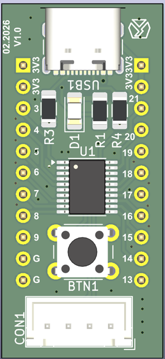
The connector itself (CON1): a 4-pin, 2.54 mm pitch header carrying SWDIO, SWCLK, GND, and NRST — the same minimal-but-complete SWD layout as before, including the reset line so a hung target can be recovered with a clean debugger-triggered reset rather than needing a power cycle. The same caveat about it being a standard pin header rather than a true "JST" connector applies, and the same suggestion stands for a future revision: a keyed/shrouded header, or an extra VTref pin, would make this connector compatible with off-the-shelf universal debug probe cables instead of requiring one wired specifically for a fixed 3.3V target.
Reset Button and Power LED
The board keeps exactly two pieces of onboard user interaction: a reset button, and a power-indicator LED (D1) that lights up whenever the board is receiving 5V from the USB-C connector.
The power LED is a small but worthwhile inclusion for debugging power issues in isolation — if the board seems dead, glancing at whether D1 is lit immediately separates "no 5V reaching the board" (check the USB-C connection and CC resistors above) from "5V is fine, something downstream is wrong" (check the regulator output, or the MCU itself), without needing a multimeter for the first diagnostic step.
Pin Breakout
With no onboard peripherals besides the reset button and power LED, essentially every GPIO the TSSOP20 package exposes is broken out along the two long edges of the board, labeled directly with pin numbers. This is the right layout choice for a board meant to be dropped into a breadboard: it maximizes the number of pins available for whatever the learner wants to wire up next, at the cost of not having friendly peripheral-name labels (e.g., "SDA"/"SCL") silkscreened next to each pin — a minor trade-off, and arguably another small nudge toward "go check the datasheet's pin assignment table," which fits the board's teaching goal.
Design Tools and Version
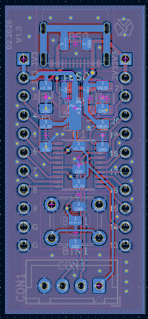
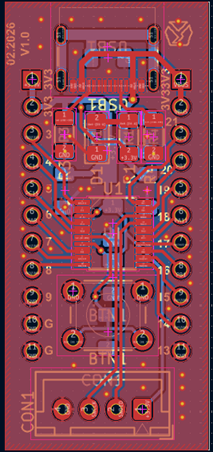
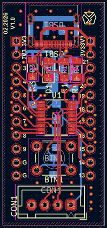
This is the first revision of this board, designed in KiCad. As with the other board in this lineup, project files and Gerbers aren't being published alongside this article, but the reasoning above — MCU selection, power-only USB-C wiring (and the CC resistor detail worth double-checking), and the SWD-only debug approach — should be enough for anyone wanting to design something similar around their own MCU of choice.
Downloads
Final Thoughts
This board is deliberately the opposite of a feature-packed dev board: one power connector, one debug connector, one reset button, one LED, and a chip with a small enough register map to actually read cover-to-cover. That's the point. For someone who's comfortable with Arduino-style digitalWrite() calls but has never opened a reference manual and configured a GPIO register by hand, or never single-stepped through an interrupt handler with a real debugger, this is meant to be the board where that first happens — with as little else on the PCB as possible to distract from it.
The trade-offs are exactly what you'd expect from that goal: no hardware acceleration for anything demanding, a small flash/RAM budget, and a debugging workflow that leans on SWD instead of a comfortable serial terminal. None of that is a flaw so much as the natural cost of a board that's trying to be small in every sense — physically, electrically, and in how much you need to understand before your first LED blinks under your own register-level code.