Building a Moving Platform Robot From Scratch
by nielspost in Circuits > Robots
6071 Views, 72 Favorites, 0 Comments
Building a Moving Platform Robot From Scratch


My name is Niels Post. I am a Computer Science student from the Netherlands. This robot is part of my internship at the Vrije Universiteit Brussel. The robot is meant for use as a simple moving platform robot. It is able to drive and turn specified distances, and receive commands wirelessly. The robot is controlled through a webinterface (see picture).
The robot itself does not have any sensors on board yet, and does not know anything about its environment. To still be able to check the position of the robot, a Raspberry Pi can be used with a camera and QR codes to see the position and rotation of the robot. The raspberry Pi hosts the webinterface that can be used to control the robot, and see the live stream.
This instructable explains the following:
- Building the robot
- Building and flashing the firmware
- Connecting the raspberry Pi
- Setting up the software on the raspberry Pi
- Setting up a test area
The robot is built using mostly 3D printed parts and some easily findable electronic parts. The firmware is written using the Arduino framework and the PlatformIO build system.
Supplies
Materials / Tools:
- A 3D printer (bed size of at least 230 x 230 mm)
- Soldering equipment
- +- 400-500 grams of 3d print filament (I used PLA)
- A way to charge 18650 batteries (mini chargers can be bought for around €5)
- 8x M3x12mm bolts
- 8x M3 nuts
- 8x M4x12mm bolts
- 8x M4 nuts
Parts
- 2X Pololu 80x10MM wheel
- 2X Pololu universal wheel hub (for 5mm shafts)
- 2X Castor wheel (50mm height, 40 mm wheel diameter)*
- 3X Lithium Ion 18650 Battery
- 1X 18650 battery pack (for 3 batteries)
Electronics
- 1X Raspberry Pi with Python3 (for controlling the robot)
- 1X Webcam (recommended: Cybertrack H3)
- 1x Arduino Due (or compatible clone)
- 1x custom PCB: Download Gerber
- 1x SSD1306 display (128x32)
- (optional) some rows of female headers**
- 2x TMC2208/9 Stepper Driver
- 2X NRF24L01+ wireless module
- 2X 17HS4401 Stepper motor
- 1X KCD1-11 Power switch
- 2X 10uF capacitor
Wires
- Female-female Jumper wires to connect the Pi to the NRF
- 1x JST-XH 2.54 2-pin (male wire + female connector)
- 2x JST-XH 2.54 4-pin (female connector only)
- 2x JST-PH-6P to JST-XH-4P cable
*I got castor wheels at a local store (https://www.action.com/nl-be/p/zwenk-en-bokwielen/... The screw holes in the 3d print parts are measured for these specific wheels. When using different wheels, drilling might be needed in the baseplate.
** Headers make replacing components easier, but the components can also be soldered on directly.
3D Printed Components
The robot mostly consists of 3D printed parts. This section details which components you need to print for the robot. Depending on the size of your 3D printer, you can print larger parts.
Always print these files
- Motorbracket-Left.stl
- Motorbracket-Right.stl
Print when your printer bed is bigger than 250x250 mm
- Baseplate.stl
Print when your printer bed is 250x250 mm or smaller
- Baseplate_Batteries.stl
- Baseplate_Due.stl
- Baseplate_Left.stl
- Baseplate_Right.stl
Print settings
For printing I used my Ender 3 Pro, printing the small files using cura with the settings below.
- Layer Height: 0.3mm
- Support: Enabled
- Adhesion: Skirt
- Ironing: Enabled
(Only for Small 3D Printers) Assembling the Printed Parts


In this step we will assemble the four puzzle-piece-like parts into the baseplate. If you printed the baseplate in one part, you can continue to the next step immediately.
For this step, you will need all 3D printed parts of the baseplate, and some glue. Make sure you use a kind of glue that bonds to 3D printed parts (like hot glue)
Make sure you have some free table space, since we will be putting the baseplate and housing flat on the table.
Test fit
Lay the parts for the baseplate out on the table. Test to see that all parts fit together properly. You need to be able to snap the parts together quickly enough for the glue not to dry in the meantime. If this is not the case, you may need to file some edges down to make it fit. After fitting, take the parts apart again.
Glue
One by one, put glue on the edges of one part, and snap it together with the next part. Make sure all parts are flat on the table after fitting. It can help to press down on the seam after snapping together to assure the parts are flat. The final part may take a bit more force to snap in place.
Scrape off any excess glue from the top of the baseplate.
Make sure the glue is dry before continuing to the next step.
Assembling the Wheel Mount


Next we are going to fit the wheel mount. For this you will need:
- (printed) Motorbracket-left.stl
- (printed) Motorbracket-right.stl
- 2x 17HS4401 Stepper motor
- 2x Pololu 80x10mm wheel
- 2x Pololu universal hub
Mounting the wheel hub
Before mounting the wheel hub, insert the black screw that came with the wheel hub into the hole on the side of the hub (not too far).
The wheel hub is mounted to the flat side of the wheel using 2 M3 bolts. Screw the bolts in through the wheel into the hub, while squeezing the hub tightly against the wheel. This will make sure the wheel does not wobble later.
Mounting the wheel to the motor
Place the motor on the table, with the connector on the back facing up. Rotate the shaft until the flat side is facing up. Slide the wheel hub over the shaft as far as it goes. Rotate the wheel until the black screw is facing the same way as the flat side of the shaft, then tighten the black screw. Now, when rotating the wheel, the motor shaft should rotate too..
Fitting the Wheel Mount


Next, you will attach the driving wheel assembly to the base. For this step you will need 8 M3 bolts and nuts. I used 12 mm long bolts, but a bit longer should not matter.
First, fit the motor inside the motor bracket. Make sure the connector is on the top (see photo).
Depending on the specific motor and the settings of your 3D printer, the motor may wobble in place. If so, you will need to put something (like a piece of hotglue or rubber) between the motor and the bracket to prevent this. The best place to do this is near the shaft of the motor.
After this, fit the assembly to the baseplate so that the motor connector comes through the square hole on the top. Then feed the bolts through from the bottom to the top (from the bracket to the baseplate), and tighten the nuts on them. Repeat this for the other wheel.
Attaching the Castor Wheels


Next, attach the castor wheels. I used M4x12 bolts, but M3 should do fine aswell. Make sure to screw the bolts in top to bottom, so they don't interfere with electrical components on the robot.
After attaching the castors, your robot should look a bit like the attached picture. You are now ready to put the electrical components in place!
Soldering the PCB


The gerber files for the PCB for this project can be found Here. You can order them at your favorite PCB manufacturing service.
To prevent the robot from becoming a mess of wires, we will be using a custom designed PCB to connect all components together. This PCB is designed as a shield for the Arduino Due, so it can easily be clicked in place.
Instead of soldering all components on directly, I will be soldering female headers onto the PCB. This way, when I (inevitably) break a component while testing, I can easily replace it. If you choose to solder the components directly, the steps are roughly the same as below, only without the headers.
When you don't have the exact specified headers, it is possible to cut headers, and use multiple headers together to form a single larger one.
Requirements
- A soldering Iron
- Soldering Tin
- The PCB
- (5x) 8-pin male header
- (1x) 10-pin male header
- (1x) 2x18-pin male header
- (1x) 2x20-pin female header
- (1x) 2x3-pin female header
- (1x) JST-XH 2.54 2-pin connector
- (2x) JST-XH 2.54 4-pin connector
- (1x) KCD1-11 switch
- (1x) 10uf capacitor
When connecting components using headers, you also need:
- (4x) 8-pin female header
- (1x) 2x4-pin female header
Soldering
To see which component goes where, have a look at the diagram on the attached picture. Make sure to solder all headers to the right side of the PCB. The top side of the PCB is the side on which all text is printed. All components go on top of the PCB except the components listed in bold above.
note: in the photo of the result, you can see a single red wire across the board. In an earlier version of the PCB, 2 nets were not connected and had to be bridged. This is NOT needed in the version that is linked in this instructable.
The Arduino Due
When done soldering, you can press the shield onto the Arduino Due. While doing this, make sure no pins are bent and end up outside the corresponding header.
Assembling the Robot


The battery Pack
Depending on the specific components you bought, you might need to solder the 2-pin XH connector to the battery pack. Make sure to match the colors of the wires when doing so
Populating the PCB
Fit the components as shown in the picture. Make sure to orient the components in the right way to prevent them from breaking/burning out.
You should have received some heatsinks with the TMC2209 drivers. I have not needed them so far, but feel free to add them.
Connecting Wires
Connect the all wires as shown, making sure to connect the power wire with the switch turned in the off position.
Try to turn it on! If connected properly, the lights on the Arduino Due should now turn on.
Flashing Firmware


To flash the firmware, you will need two things installed:
- PlatformIO (The easiest way to install is in VSCode: PlatformIO IDE)
- Git (Download)
Cloning the repository
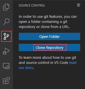
- Open a VSCode, and select Source Control -> Clone repository. If clone repository is not available, you may need to file->Close Folder.
- Enter the link of the repository and press enter https://github.com/Niels-Post/MP-Firm
- Select the folder you wish to save the project in.
Building the firmware
To build the firmware,
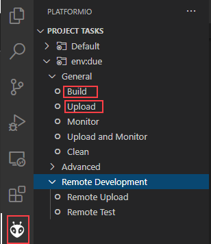
- Click on PlatformIO in the sidebar (the little alien head),
- click env:due->General->Build.
Bitbang I2C edit
At the time of writing, the build will likely fail first. To make it work, a small adjustment needs to be made in a library dependency. To do this,
- open the following file:
.pio/libdeps/due/Bitbang_I2C/src/BitBang_I2C.cpp - Adjust the following line (linenr 559 for me)
#if defined(TEENSYDUINO) || defined( __AVR__ ) || defined( NRF52 ) || defined ( ARDUINO_ARCH_NRF52840 ) - Add the following to the end of it (including the ||):
|| defined(ARDUINO_ARCH_SAM)
After this, building should succeed.
Uploading
- Connect the Arduino Due to your computer, using the usb port closest to the power jack
- Open PlatformIO in the VSCode sidebar
- click env:due->General->Upload
- When the process is done, the Due should restart and show "Robot ID: 0" on the OLED display
Wiring Up the Raspberry Pi

In this step we will allowing the raspberry pi to communicate wirelessly, and see the robot using a webcam.
Wireless communication
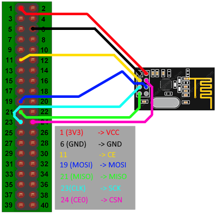
To be able to control the robot wirelessly, the raspberry pi needs the same wireless transceiver as the robot.To connect it, use female-female jumper wires, and connect the NRF chip like shown in the picture.
Make sure to connect the NRF to 3.3 volts, not to 5V!
Should you later have problems with communication between the robot and the Pi, you can try to add a 10uF capacitor between 3V3 and Ground (as close to the NRF24l) as possible.
Power
Make sure you have an adequate power supply when using a Raspberry Pi. They often have issues when they cannot get enough power from their supply. Look at this link for more information.
Installing the Controller Software on the Raspberry Pi
Prerequisites
For this step, it is assumed that you already have the Raspberry Pi installed and set up as SSH server. If not, please look at Installing a Pi OS, Setting up Wireless and SSH (I recommend Option 3 for SSH).
Getting the repository
All code for the controller software can be found in a single Git repository. To download it to your Pi, do the following:
- Open an ssh connection into your Pi.
- Clone the repository:
git clone https://github.com/Niels-Post/MP-Firm-Controller - Change into the directory
cd warehouse-pmsv-tracker
Installing dependencies
The software depends on a number of libraries. Luckily, they can all be installed at once:
- Execute the following command
pip install -r requirements.txt
After this, the software should be ready to run!
Setting Up the Test Environment

Aruco Codes
The codes used to detect and track the robots' position are uploaded to the git repository of the controller software, in the folder resources/aruco_codes. Print at least five of these markers on A4 paper. Four for the testing area, and one for the robot itself. The robot code needs to be small, but the testarea codes can be either small or big.
Before cutting out the markers, note down which ID each marker corresponds to on the back of the page. Per page, markers are ordered top-left, top-right, bottom-left, bottom-right.
Cut out the markers, but make sure to leave some white space at the edges. This makes detecting the marker on dark backgrounds easier
Mounting the camera
Like mentioned before, the robot uses a webcam to know its position. To do this the camera must be placed as close to the ceiling as possible. The easiest way to do this is to mount the webcam to a high shelf. If you have none, some double sided sticky tape did the trick for me.
Although the software automatically corrects the image as much as possible, I advise to have the camera aimed as perpendicular to the floor as possible, to have the testarea appear as rectangular as possible.
Set up
- Connect the camera to the raspberry pi
- Lay out four aruco markers in a square visible to the camera
Make sure you know the dimensions of this square - Paste one marker (different than the 4 used previously) to the battery cover of the robot
The end result should look something like the attached picture
Configuration
The controller software needs to know which markers make up the testarea, and how large the testarea actually is. To set this up, make the following code changes:
- On the Pi, open warehouse_pmsv_tracker/app/PMSVInterface.py
- Change the variable testarea_corner_markers to match the ids of the markers you laid out
The order is (topleft, topright, bottomleft, bottomright) - Change testarea_dimensions to the dimensions of the square:
The order for this is (x(unimportant), y(unimportant), width (in mm), height (in mm))
Running it
To run the software, simply start run_webinterface.sh through the SSH connection. The webinterface should now be available on http://[PI_IP_ADDRESS]:5000.
All Done!
That's it! You have now built a moving platform robot!
If you want to change the firmware to fit your needs, please refer to the documentation in the github repositories to learn more about the inner workings of the firmware.
If you have any questions, please contact me on this email.