Building a Neo Geo Stick USB Adapter
14588 Views, 27 Favorites, 0 Comments
Building a Neo Geo Stick USB Adapter


The Neo Geo AES from SNK was a glorious home arcade machine released in 1990. However it was and still is quite expensive. Games are massive cartridges of multiple megabits. Back in early 90's you can easily imagine how advanced this was.
For retro gamers, this is an expensive leisure. As I'm a proud owner of an AES system with 2 joysticks, I went down the shady road of emulators. But I wasn't able to just plug the controllers.
This instructable explains how to very easily build an adapter.
Else, you can get one here at 28$. Looks like there are generic adapters for 15 pin game controllers around 13€, don't know about these.
Note that in 2018 a Neo Geo Mini has been released. That can be an option to cheaply discover that 1st-Class gaming system!
If you'd like to support me in writing other instructables, please buy hardware from the Amazon sponsored links.
Also, this instructable is now also available from my personal page : http://stuffblog.dullier.eu/
USB Converter Part

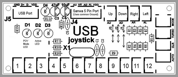
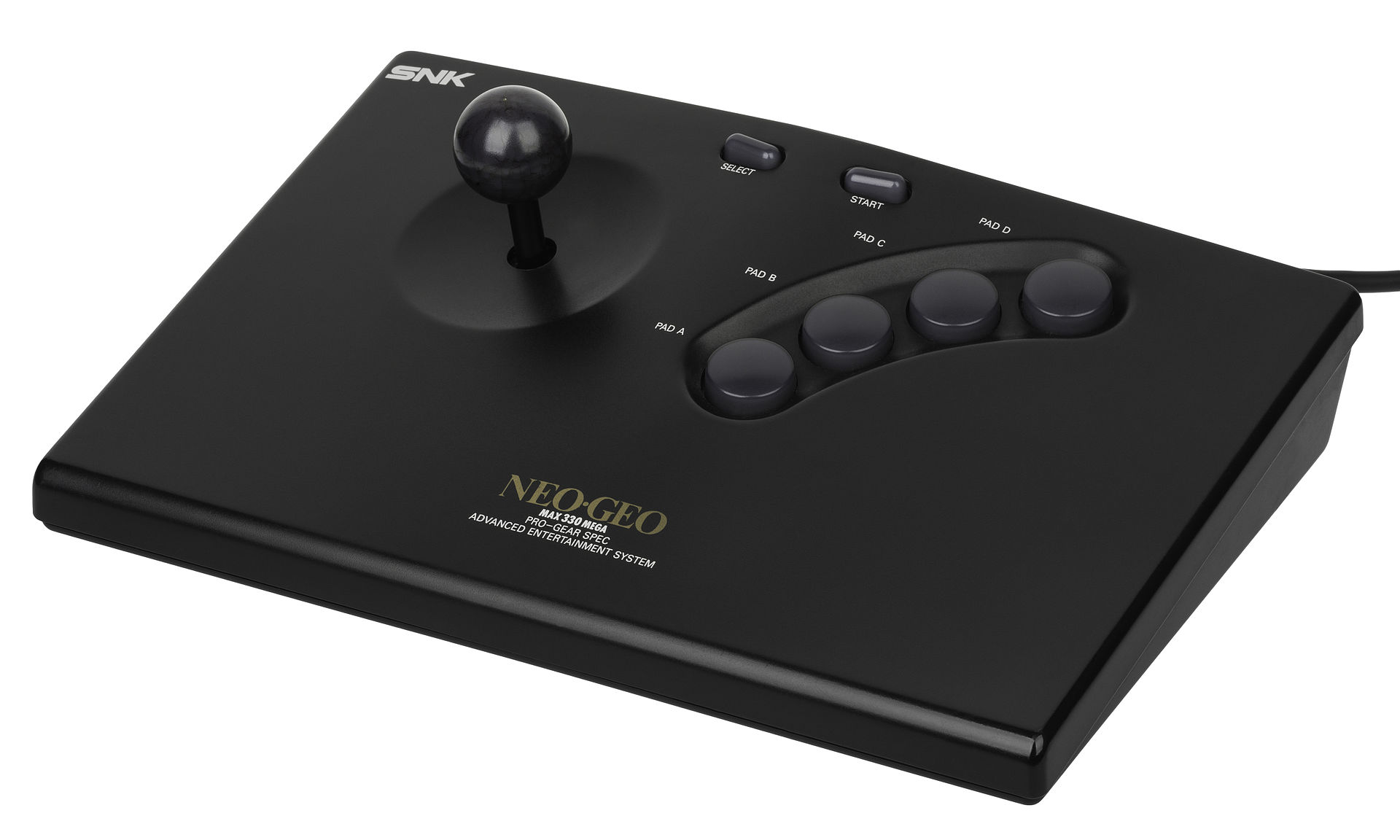
The AES game controller consists of :
- A joystick : 4 contacts for Up, Down, Left and Right
- 4 action buttons : A, B, C, D
- 2 function buttons : Select, Start
Pretty basic :-)
All buttons share a common ground so that's actually only 4 contacts for the stick and 6 for the buttons to manage a whole analog controller. This is a perfect option for "Zero Delay USB encoder" boards. You can get two for as low as around 18 USD. They measure each ~86mm x 35mm. Perfect to fit into a pretty small box.
This kind of kit comes with cables readily plugable in home made arcade cabinets. However we'll have to cut that a bit to solder on a DB 15 male connector.
Soldering the DSUB-15
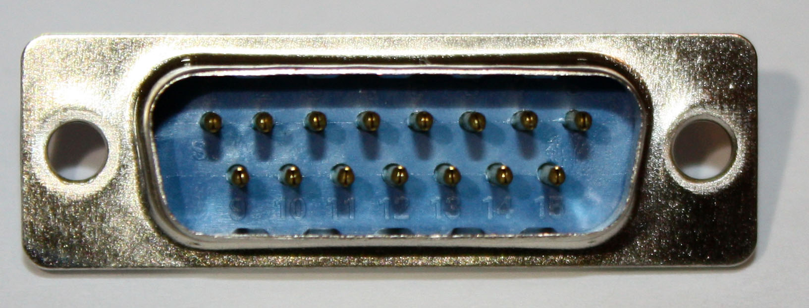


If you don't have a soldering iron, that 40-Watt Weller soldering station is a pretty good deal.
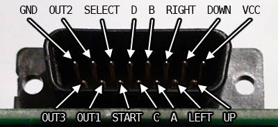
For a regular stick, solder wires so that:
- Pin 1 = GND
- Pin 2 = Credit (Select)
- Pin 4 = Button 4
- Pin 5 = Button 2
- Pin 6 = Right
- Pin 7 = Down
- Pin 8 : VCC [+5V; Get power from USB port; required for Neo Geo CD controller]
- Pin 11 = Start
- Pin 12 = Button 3
- Pin 13 = Button 1
- Pin 14 = Left
- Pin 15 = Up
Note you can also solder:
- Pin 3: Button 5 (Out 1)
- Pin 9 : Button 7 (Out 3)
-
Pin 10 : Button 6 (Out 2)
For full reference, see this page at Neo Geo Dev.
Connecting the D-Sub to the Encoder Board


The back of the PCB show that the outer green track indeed connect the outer pins together. Since we have a common ground in stick and encoder, one single ground wire is required. Keep the one you prefer :-)
We need only that one to be connected to the D-SUB GND pin.
Make sure to use a diagonal cutting pliers to have cable cut short.
Don't forget to test before cutting the wires.
NOTE : On the PCB, the "common ground" is actually +5V coming straight from the USB port. This is the opposite of the Neo geo controller having a single GND and multiple "power lines" to have bits switching to "1" (there is power coming in). This is normally not an issue since this is the expected behavior of the encoder. The stick just connects the pins together at encoder after all.
Putting All Together


Get a project box to fit everything in. Mine was close to this 100x50x21mm one.
I used a regular Dremel rotary tool to cutout for the DB 15 connector and USB cable.
I also drilled 2 holes to put screw/nut on each side to hold that tight. For that, of course again the Dremel, but with a specific very small Dremel drill bit. It might be a good idea to use a keyless chuck to prevent any misuse.
Once plugged into a Windows machine, it'll work out of the box. You'll however have to map the buttons in your emulator of choice. This adapter will work for any emulator/game as long as it uses a joystick.
Note that cables might be short some times, consider buying a long (3m or more) USB extension cable. I own 2 cables of 5m but found that 5m cable with integrated USB hub to be a super nice idea (don't forget 5V DC power adapter), also for other game pads!
If cables are an issue, well, get a wireless game controller like the Logitech F710.
Emulator Setup : WinKawaks
.png)
.png)

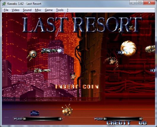
Getting ready BEFORE starting emulator / software / game:
- Plug stick into adapter
- Plug USB cable from adapter into computer
- Run the Windows' "Game Controllers" tool (from start menu, type JOY.CPL)
- Make sure you see your controller
- Go to properties of that controller and test all buttons. Fix cabling as needed.
Once the stick is properly working from Windows, run your soft and set the controller.
In WinKawaks:
- Go get WinKawaks
- Unzip it to some folder
- Have a few roms around
- Start WinKawaks
- Setup input devices
This site explains different key setups.
About Neo Geo Joypads
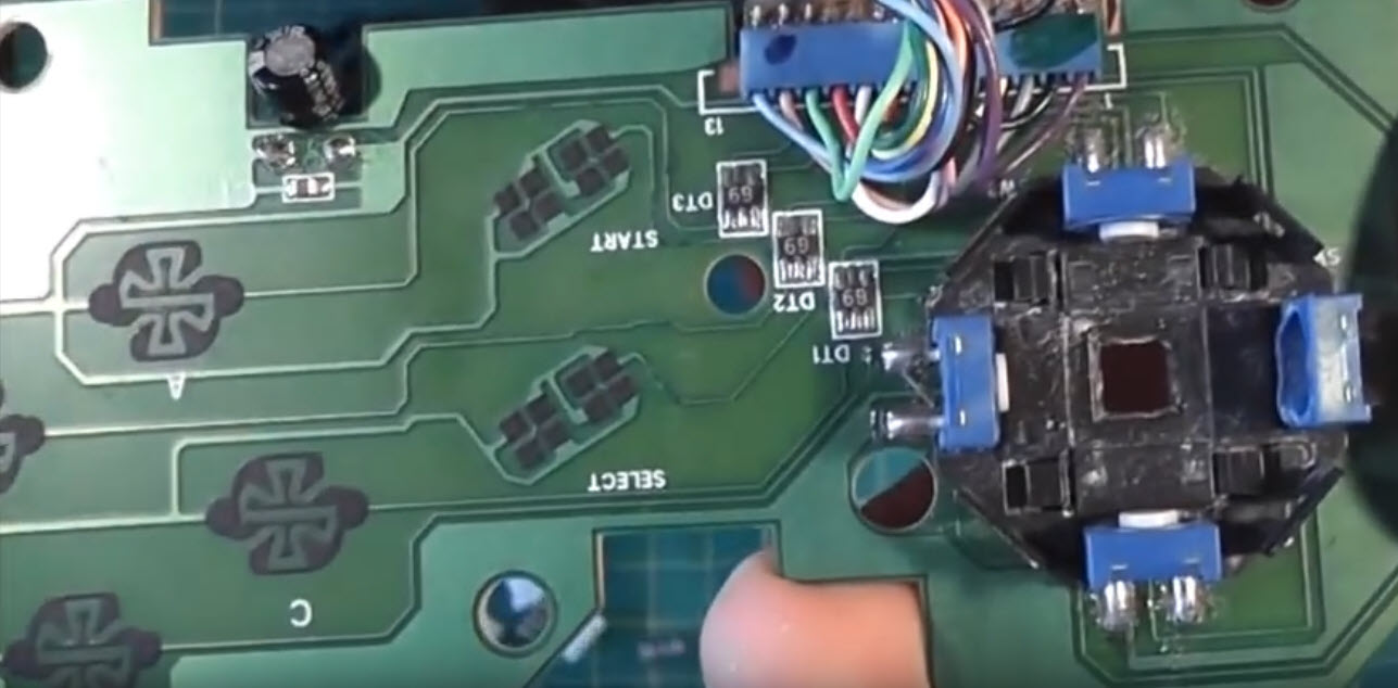
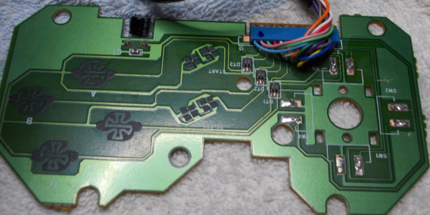
Discussing with people in comments, it appears the Neo Geo CD Controller has something special.
Update 2018-10-23.
When plugged into adapter, all buttons (ABCD, Select/Sart but not stick) "are pressed".
It's currently unknown why. I've attached images from below videos to illustrate the PCB.
Final Words
In the first place this type of encoder is aimed at building custom arcade cabinets. Feel free to buy some buttons/sticks kits and build your own setup!
If you prefer that way, buy a fully furnished arcade kit including sticks, buttons, wires and encoders!