Building a WiFi Air Quality Monitor With MQTT and Tasmota (BME680, ESP32)
by taste_the_code in Circuits > Gadgets
270 Views, 2 Favorites, 0 Comments
Building a WiFi Air Quality Monitor With MQTT and Tasmota (BME680, ESP32)
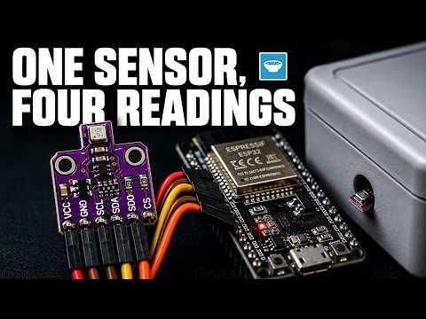
I wanted a simple way to keep track of the conditions inside a warehouse, so I built a small wireless environment monitor around the Bosch BME680 sensor and an ESP32 board. This one sensor gives me temperature, humidity, air pressure, and a general air quality reading all at once, and the whole thing publishes its data over MQTT so I can view it from anywhere. The best part is that no code is involved. The ESP32 runs Tasmota, a ready made firmware that handles the sensor, the web interface, and the messaging for you.
Everything fits inside a small electrical box that can be screwed to a wall on site.
Supplies
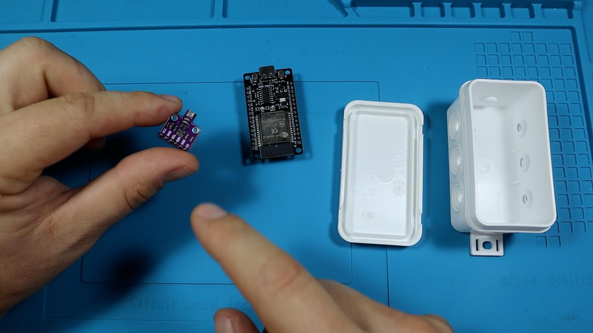
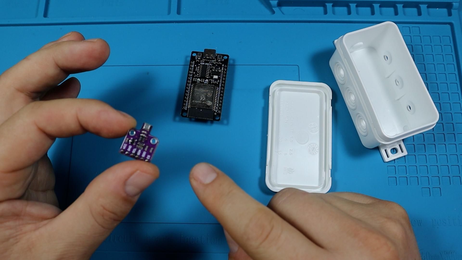
On the hardware side you need a BME680 breakout board, which is the six pin version that runs on 3.3 V, and an ESP32 development board with pin headers. To connect the two you need four female to female Dupont jumper cables. I used brown for ground, red for 3.3 V, yellow for the clock line, and orange for the data line, but any colours work as long as you stay consistent. You also need a USB cable to power and program the board, and a small electrical enclosure box to house everything. A drill or a hobby knife is handy for making the cable and sensor openings in the box.
On the software side, all you need is a computer with a Chromium based browser such as Chrome or Edge, since the Tasmota web installer flashes the board directly from the browser. You will also want access to an MQTT broker. This can be a Home Assistant instance, a self hosted broker, or a hosted platform. I used ding.mk, which works over standard MQTT.
- BME680 Sensor: https://s.click.aliexpress.com/e/_c3iIDMmL
- ESP32 Development Board: https://s.click.aliexpress.com/e/_c3PfpZXZ
- Tasmota Firmware Web Installer: https://tasmota.github.io/install/
- Dupont Jumper Cables (Female to Female): https://s.click.aliexpress.com/e/_c3fr8y5p
- Electrical Enclosure Box: https://s.click.aliexpress.com/e/_c3XEbZl5
- ding.mk Platform: https://ding.mk/en
- ding.mk Video: https://youtu.be/9simFNsFohA
- Bench Power Supply: https://s.click.aliexpress.com/e/_c3OoaCuB
- Soldering Station: https://s.click.aliexpress.com/e/_c3fAwU4n
- Multimeter: https://s.click.aliexpress.com/e/_c3PfXcr9
- Microscope: https://s.click.aliexpress.com/e/_c4su1Ycr
How the System Works
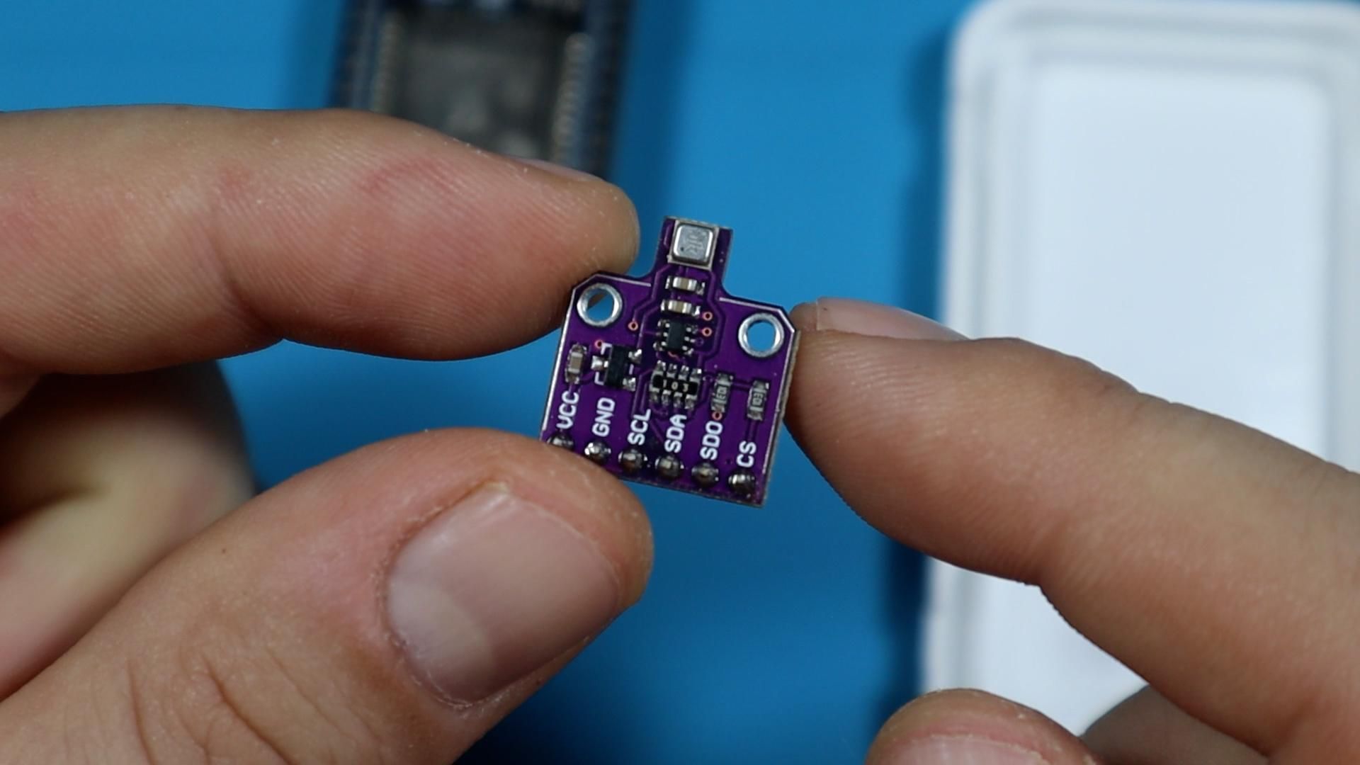
The BME680 is a combined sensor from Bosch. Inside one small package it measures temperature, humidity, barometric air pressure, and volatile organic compounds in the air. That last measurement does not identify a specific gas or give you a concentration figure. What it gives you is a general indication of air quality, which is often exactly what you want when you are monitoring a room or a storage space rather than hunting for a particular chemical.
The sensor talks to the microcontroller over I2C. This is a two wire communication protocol, so you need a clock line called SCL and a data line called SDA, plus power and ground. That is four connections in total. The breakout board actually has six pins, and the two extras on the end are for SPI mode and chip select, which only matter if you are running several sensors on the same bus. For a single sensor you can ignore them.
The ESP32 handles reading the sensor and getting the data onto the network. Rather than writing firmware for that, we use Tasmota, which already knows how to talk to the BME680 and how to publish readings to an MQTT broker.
Flash Tasmota Onto the ESP32
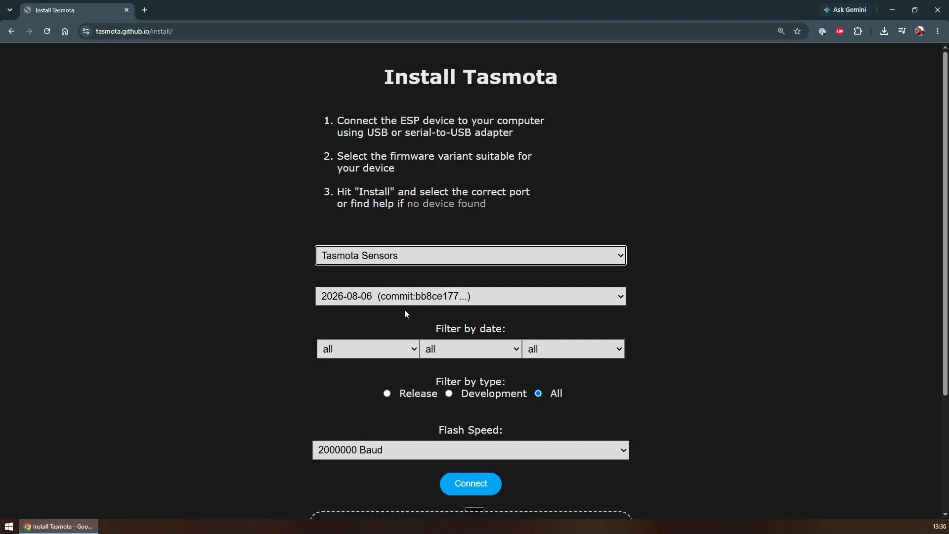
Plug the ESP32 into your computer with a USB cable, then open the Tasmota web installer page in your browser. The flashing happens entirely in the browser, so there is nothing to install on your machine.
Before connecting, choose the firmware variant. This is the most important choice on the page. You need the Tasmota Sensors variant, because that is the build that contains the I2C driver for the BME680. The standard Tasmota build will flash fine but will never see your sensor. You can also pick a specific release version if you want, but the default is fine, and so is the default flash speed.
Click connect, choose the COM port your board appeared on, and wait a couple of seconds for the connection to establish. Then choose to erase the device and install. Erasing first gives you a clean slate and avoids leftover settings causing confusion later.
There is a good chance your first attempt fails with a message saying it could not enter bootloader mode. This is very common with ESP32 boards and does not mean anything is broken. Some boards cannot automatically switch the chip into flashing mode over USB.
The fix takes ten seconds. Disconnect the port in the installer, then hold down the boot button on the ESP32 while you reconnect. Holding that button forces the chip into bootloader mode manually. Select the port again and run erase and install one more time. This time you should see it go into erasing mode and then start writing the firmware.
The full install takes a few minutes depending on your board and computer, so leave it alone until it finishes.
Connect the Board to Wi-Fi
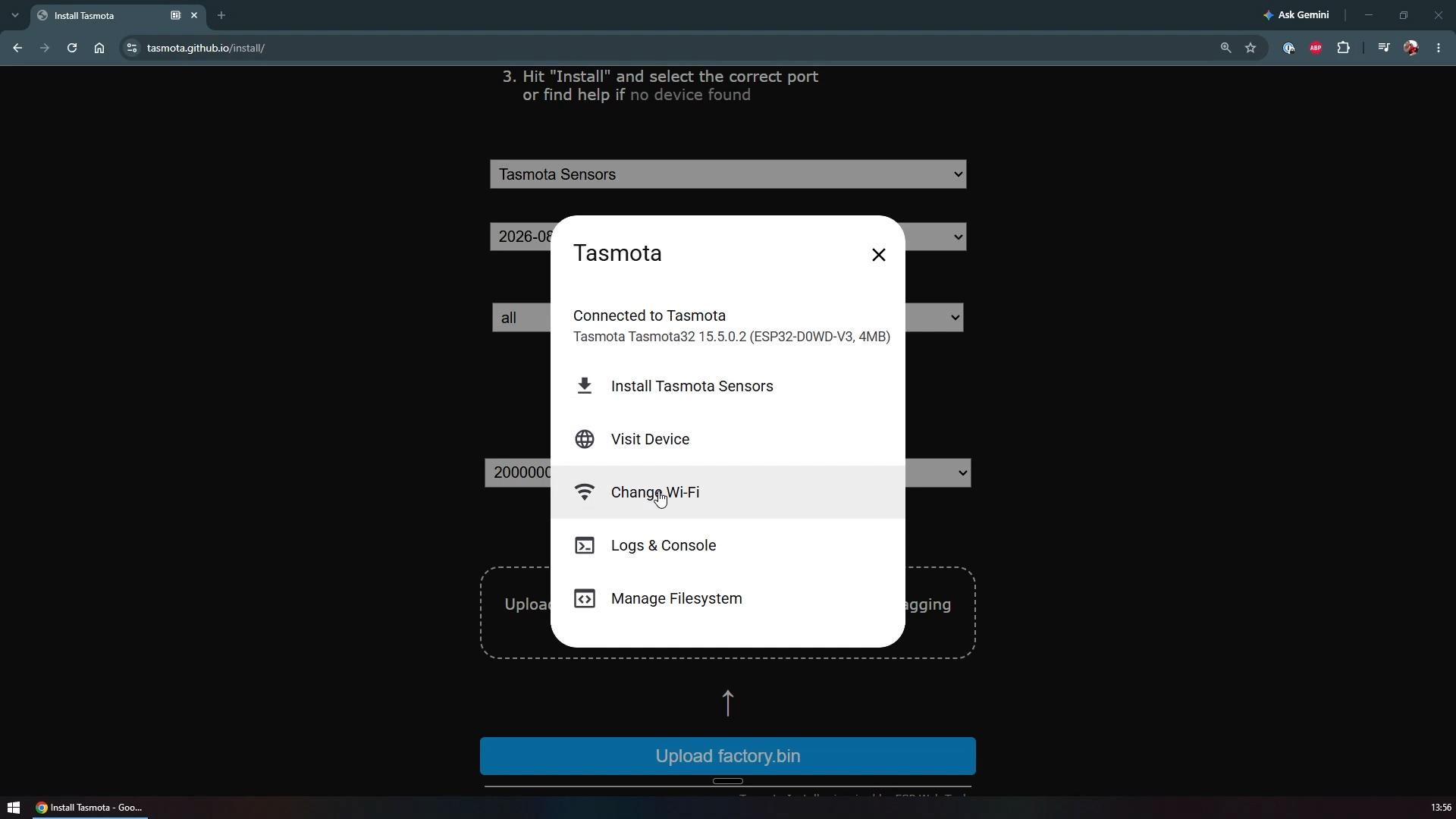
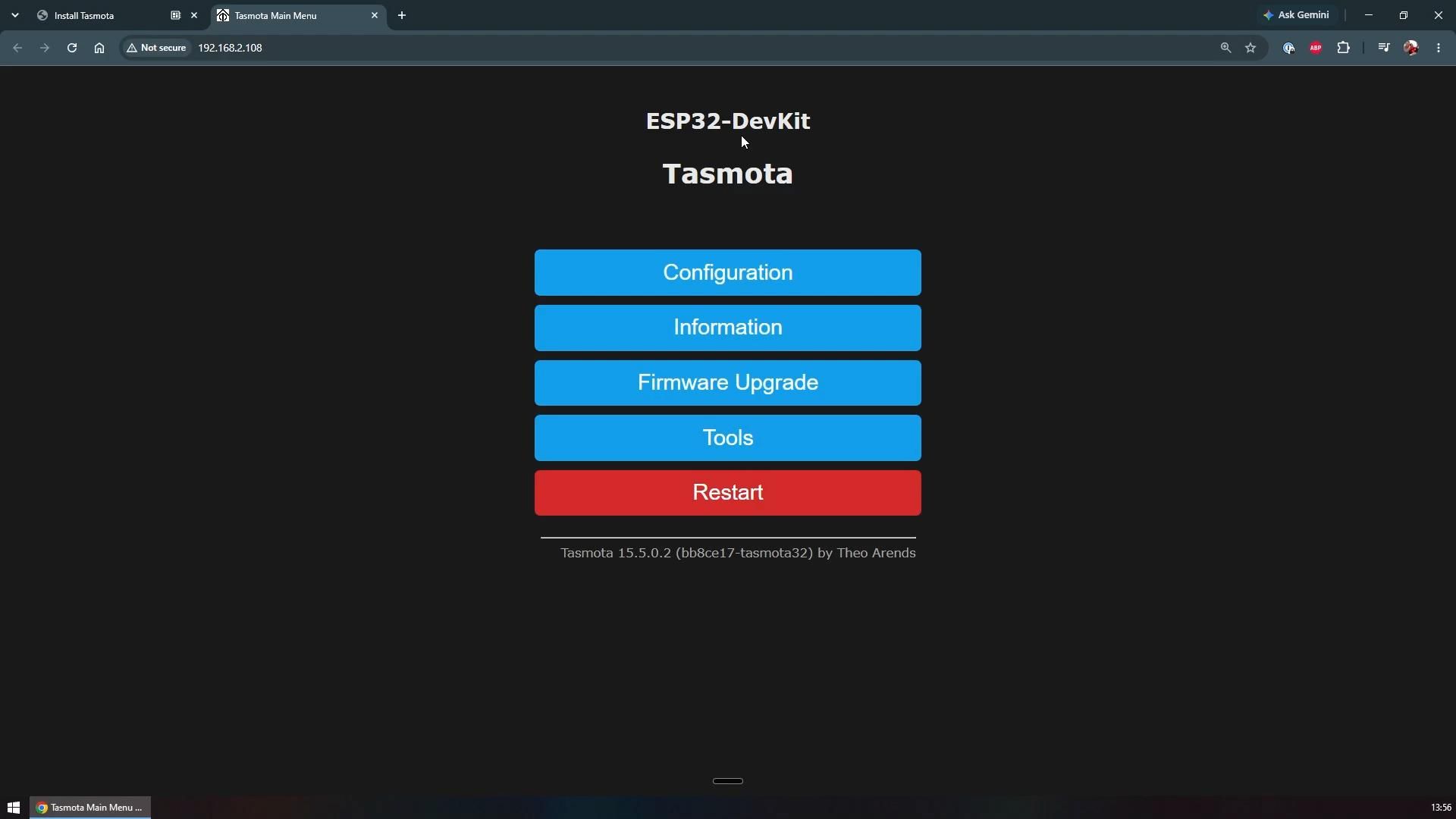
A freshly flashed board has no Wi-Fi credentials, so it cannot get on your network yet. The installer offers to configure this for you right after the install completes, which is the easiest route. Pick your network from the list, type in your password, and connect.
After a short wait the device joins the network and a visit device button appears. Clicking it opens the Tasmota web interface that is now running on the board itself. Everything from here on happens in that interface, so it is worth bookmarking the address.
Wire the Sensor to the Board
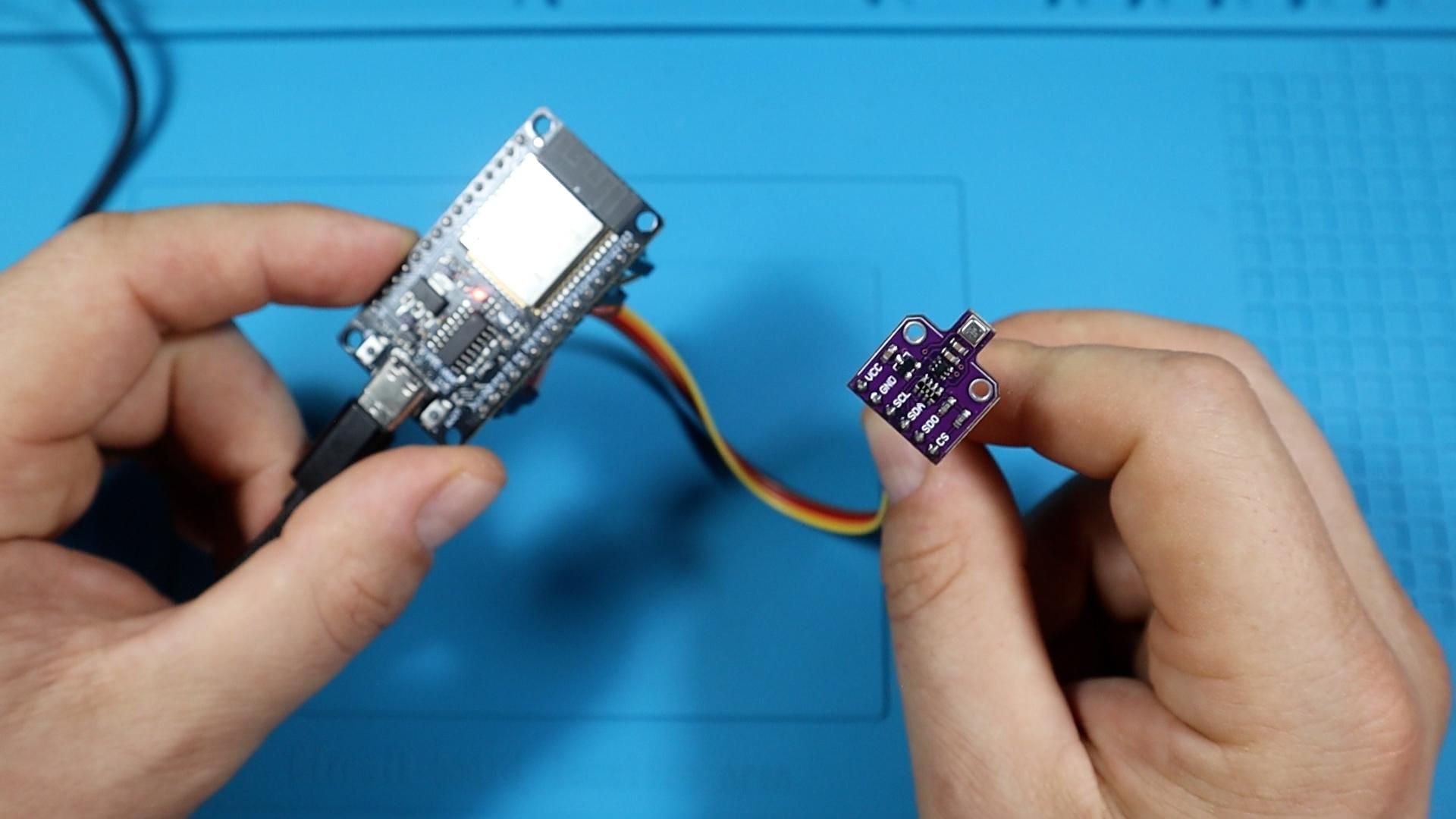
Unplug the board from USB before wiring anything. Both the sensor breakout and the ESP32 have male pins, so female to female Dupont cables connect them directly with no soldering.
Start with power. The VCC pin on the sensor goes to the 3.3 V pin on the ESP32, and the ground pin on the sensor goes to any ground pin on the board. Do not use the 5 V pin, since this sensor breakout is designed for 3.3 V.
Then the two communication wires. SCL on the sensor is the clock line and it connects to pin D22 on the ESP32. SDA on the sensor is the data line and it connects to pin D21. These are the standard I2C pins on most ESP32 boards and they work reliably.
That is all four wires. Using consistent colors makes it much easier to check your work later, so I keep brown for ground, red for 3.3 V, yellow for SCL, and orange for SDA.
Configure the GPIO Pins in Tasmota
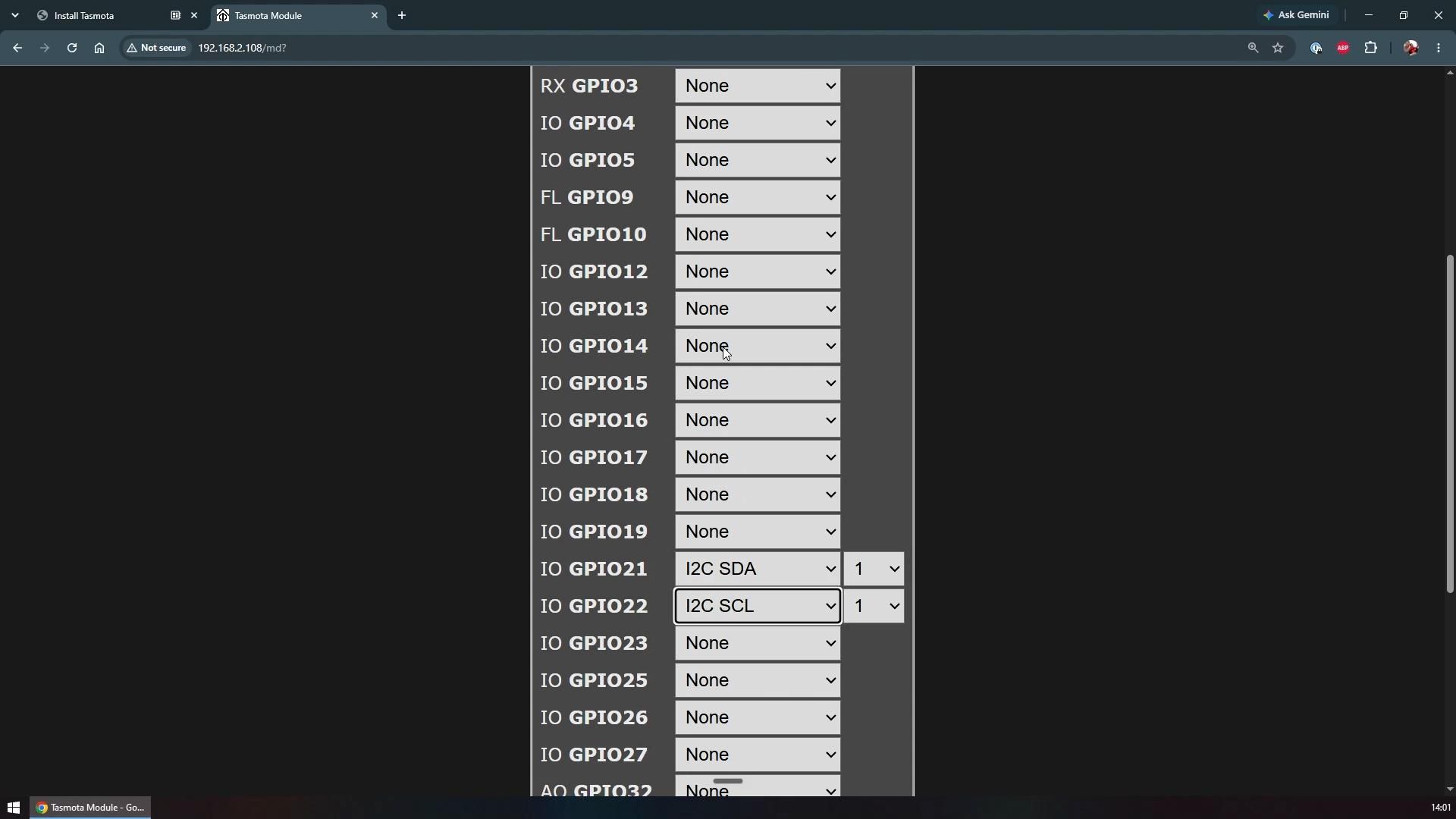
Tasmota does not guess what you have wired up, so you have to tell it. Power the board back up, open its web interface, and go to Configuration and then Configure Module.
That page lists the usable pins on the board with a dropdown next to each one. The D21 and D22 labels printed on the board correspond to GPIO 21 and GPIO 22 in the firmware. Set GPIO 21 to I2C SDA and set GPIO 22 to I2C SCL, then save.
The device restarts as soon as you save. Once it comes back, the sensor readings should appear on the main page.
Test It
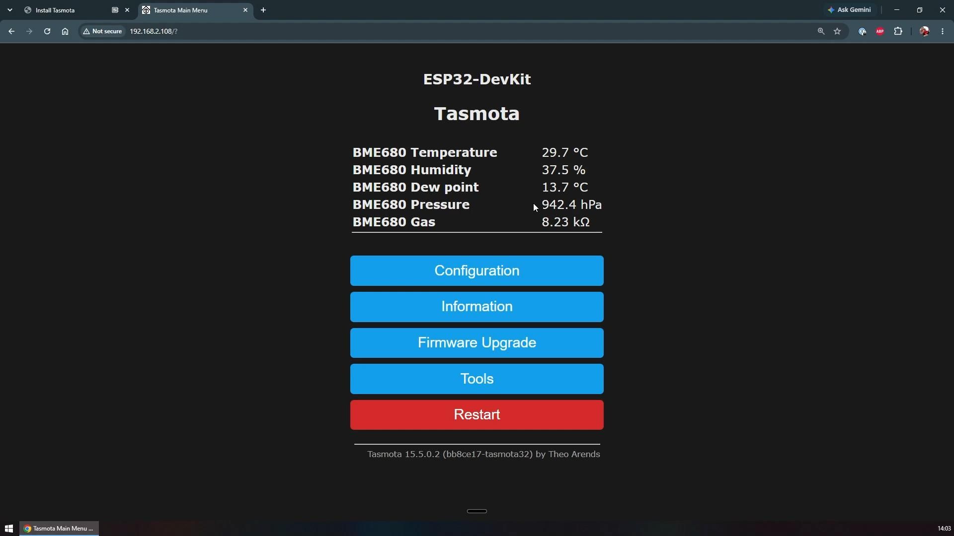
After the restart, look at the main page of the Tasmota interface. You should see a block of readings appear: temperature in degrees, relative humidity as a percentage, dew point, and air pressure in hPa. When I first got mine working it showed 29.8 degrees, 37.7 percent humidity, a dew point of 13.7 degrees, and 942 hPa.
If nothing shows up, the most likely reason is that you wired the sensor while the board was powered on. Tasmota scans the I2C bus at boot, so a sensor that was not connected at that moment never gets detected. Unplug the USB cable, plug it back in for a proper power cycle, and the readings should appear. This caught me out the first time and the fix really is that simple.
Send the Data Over MQTT
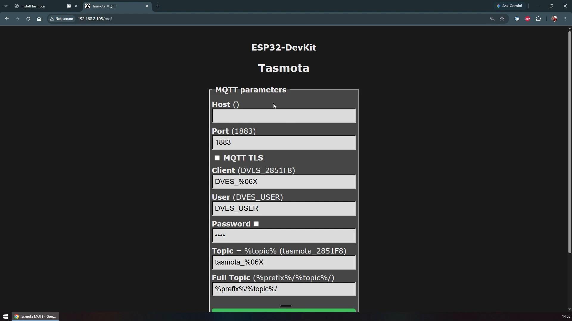
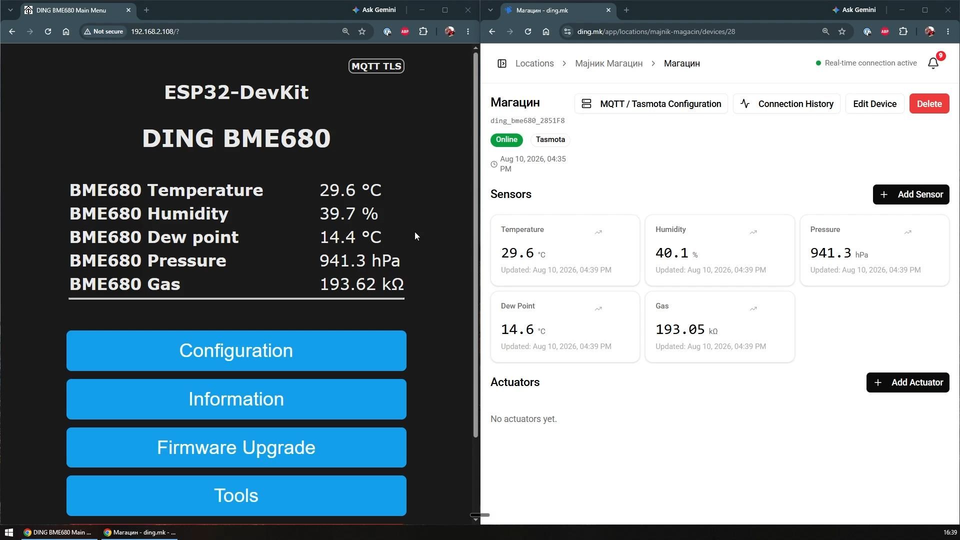
Readings on a local web page are only useful when you are on the same network with a browser open. To make this a real monitor, the data needs to go somewhere central, and MQTT is how that happens. MQTT is a lightweight messaging protocol where the device publishes its readings to a broker and anything else can subscribe to them.
In the Tasmota interface, go to Configuration and then Configure MQTT. Fill in the host, port, username, password, and topic details from your MQTT provider. These values are different for every broker, so take them from your provider's setup page. If you run Home Assistant, point it at your Home Assistant broker. I pointed mine at ding.mk and the values showed up in its mobile app and web dashboard within seconds.
One thing to be aware of is the update interval. Tasmota publishes on a timer, and by default that is once every 5 minutes/. I changed mine to be once every 10 seconds, so there is a small delay between a reading changing and it showing on your dashboard. You can add device rules to push an update the moment a value changes, but for general environment monitoring, ten seconds is plenty.
Put It in the Enclosure
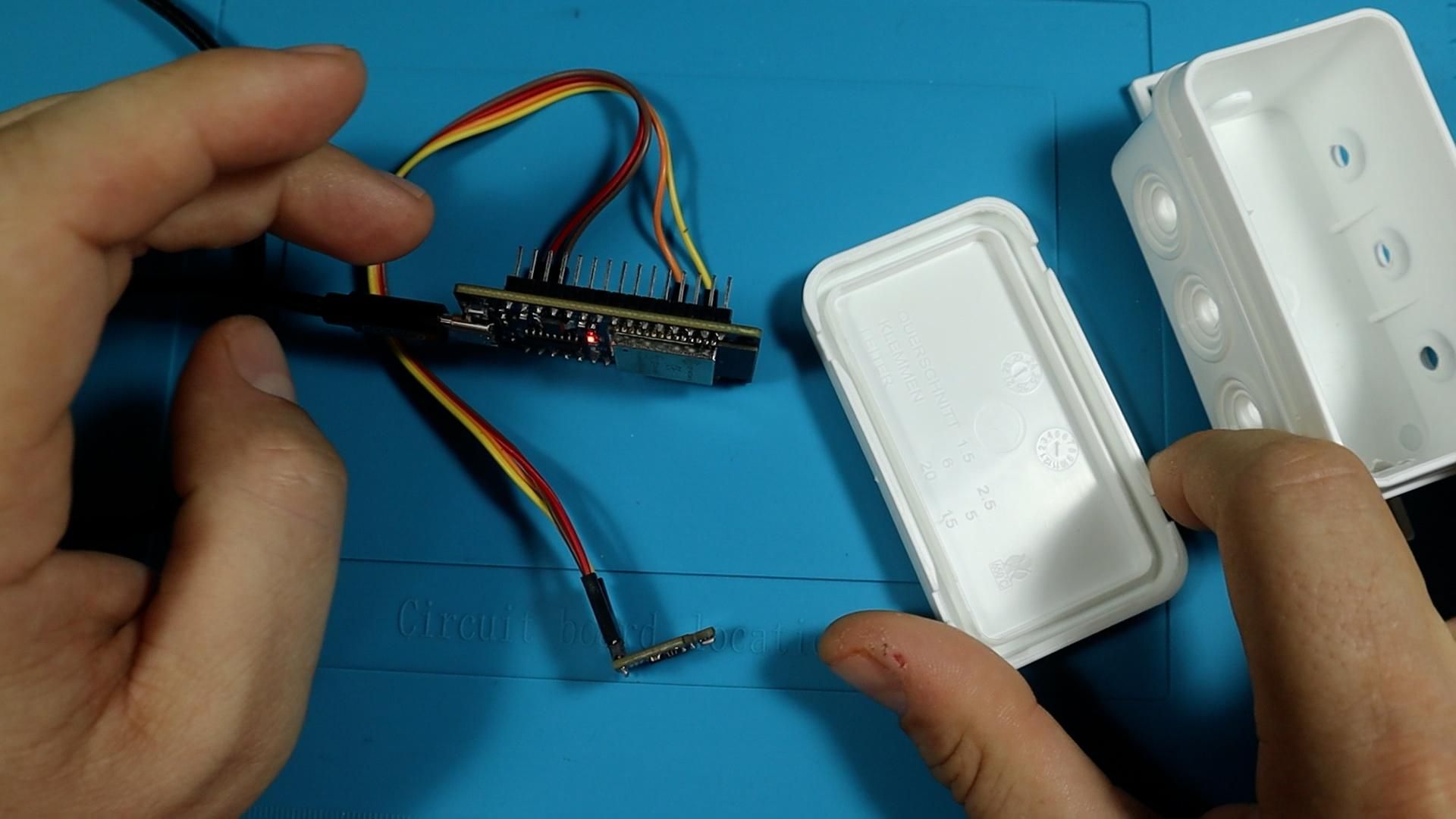
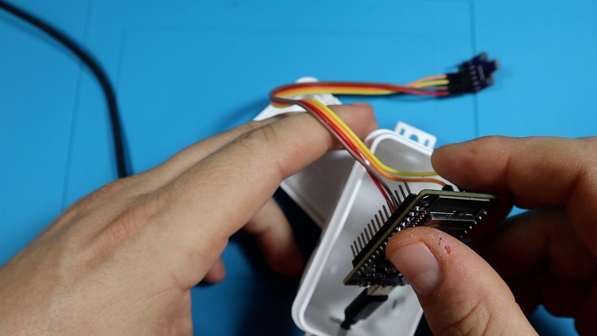
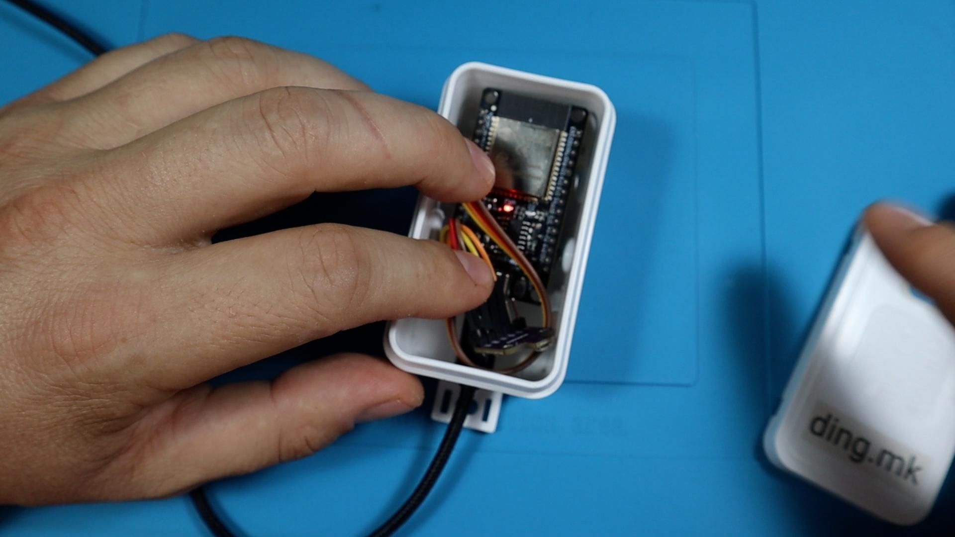
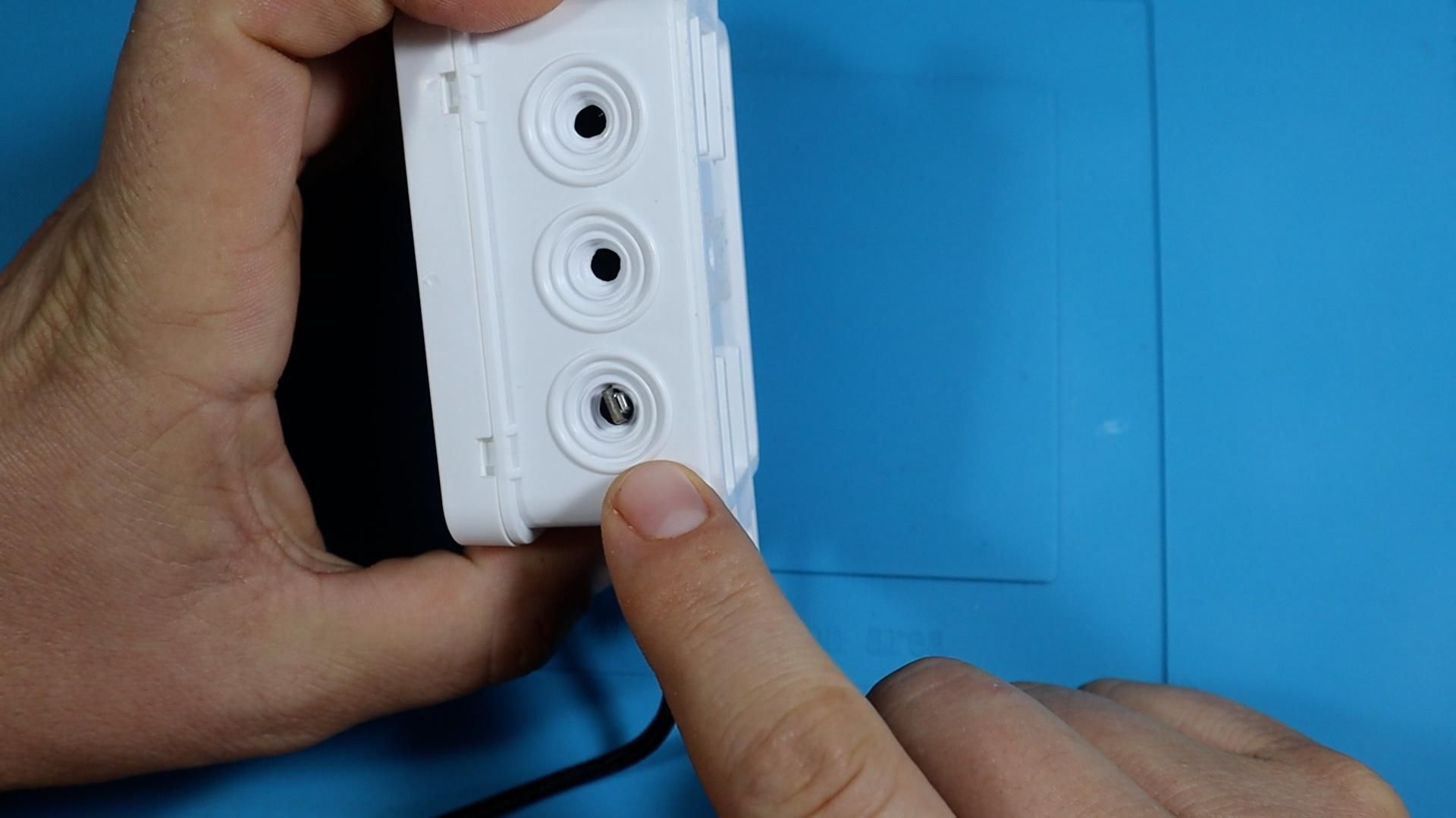
The last step is packaging. Make a hole in the side of the electrical box just big enough for the USB cable to pass through, and a second smaller opening for the sensor. Disconnect the USB cable, thread it through the hole first, then plug it back into the board and place the board inside the box.
Here is the important detail. Do not seal the sensor inside the box. The ESP32 generates a small amount of heat, and inside a closed plastic enclosure that heat has nowhere to go, so the sensor ends up reading the temperature of the box instead of the room. I originally planned to rely on airflow through the holes, then changed my mind once I saw the layout. Position the sensor so the tip of it sticks out through the wall of the box. That way it measures the actual outside air and any warmth building up inside is irrelevant.
Close the box and check the web interface one more time to confirm the readings are still updating. Then it is ready to mount wherever you need it.
Conclusion
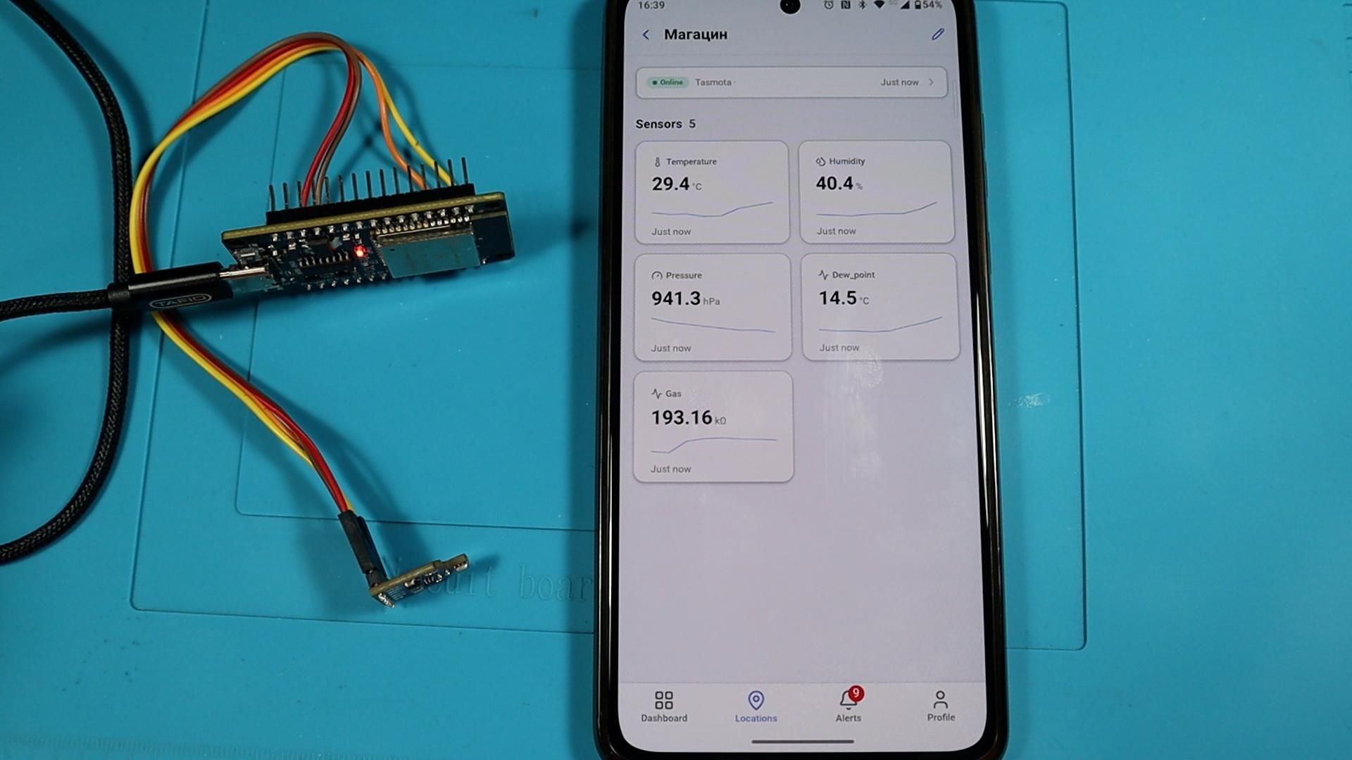
For a project with four wires and no code, this gives you a lot. One BME680 covers temperature, humidity, air pressure, and air quality, and Tasmota turns an ordinary ESP32 into a networked sensor node with a web interface and MQTT publishing built in. Total build time is well under an hour once you know about the boot button trick and the power cycle after wiring.
There is plenty of room to take it further. You could add Tasmota rules so updates publish immediately when a value changes, run several units around a building and tell them apart by topic, or feed the data into Home Assistant to trigger fans, heaters, or alerts automatically.
If you want to see more builds like this one, follow along on the Taste The Code YouTube channel.