CNG Multidevice Sale Tracker
by Crazy_ Whale in Circuits > Microcontrollers
51 Views, 1 Favorites, 0 Comments
CNG Multidevice Sale Tracker
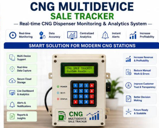
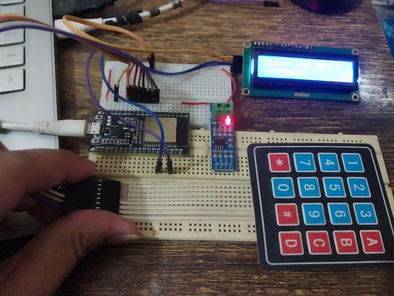
An ESP32-powered IoT system that plugs into any CNG fuel dispenser's RS-485 Modbus port, automatically captures every sale vehicle number, quantity, and amount and beams it over WiFi to a live React dashboard, giving gas station operators real-time visibility, vehicle tracking, and daily/weekly/monthly revenue reports across all dispenser arms from a single screen.
Supplies
Description
CNG Multi-Device Sale Tracker — Complete Build Guide
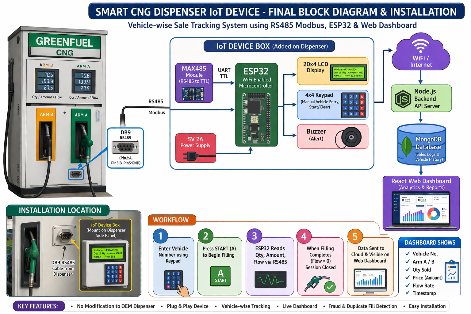
What you'll build: A real-time IoT system that connects CNG (Compressed Natural Gas) fuel dispensers to a cloud dashboard. Each dispenser gets an ESP32 that reads sale data over RS-485 Modbus, accepts vehicle number input via a 4×4 keypad, shows status on a 16×2 LCD, and POSTs every completed sale to a Node.js backend. A React dashboard gives operators a live view of all dispensers, vehicle tracking, and daily/weekly/monthly reports.
Components Used
- ESP32 Dev Board
- RS-485 Module
- 4×4 Matrix Keypad
- 16×2 LCD Display
- RS-485 cable
- USB-A to Micro-USB
- Dupont jumper wires
- Breadboard or PCB
- 5 V power supply
- Project enclosure box
System Architecture
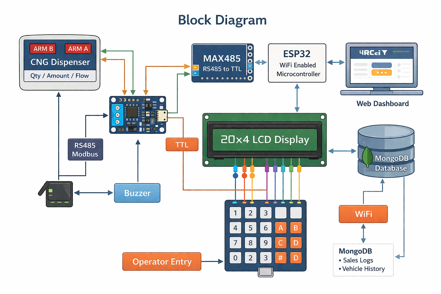
Hardware Assembly
3.1 — Prepare the ESP32
1. Plug the ESP32 into your breadboard so the two rows of pins straddle the center gap.
2. Leave at least 3 rows of free breadboard above and below the ESP32 for jumper wires.
3. If your ESP32 doesn't come with headers soldered, solder 2.54 mm male headers now.
3.2 — Wire the RS-485 Module
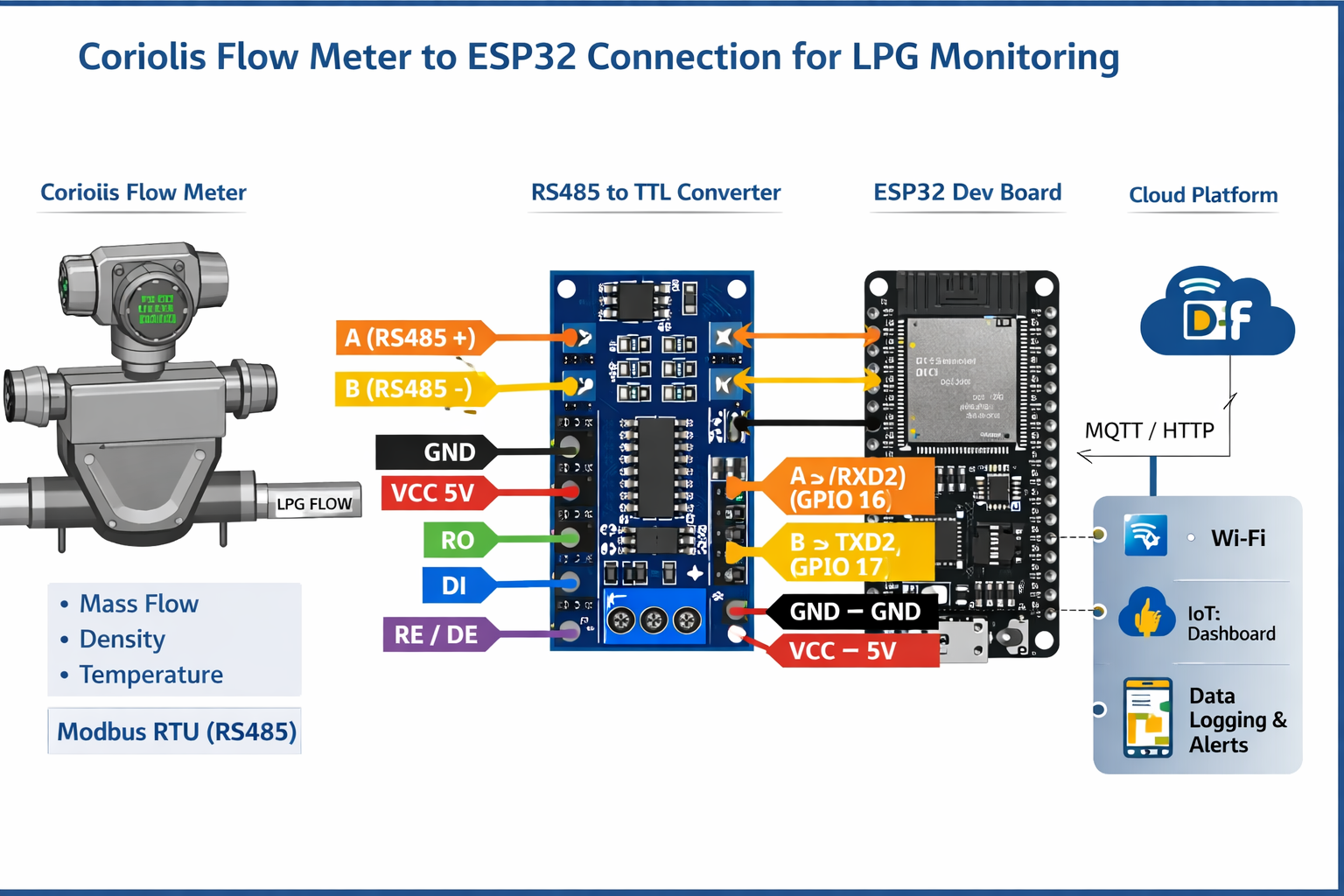
The RS-485 module (MAX485 / SP3485) translates the ESP32's TTL UART signals to the differential A/B signals used by Modbus.
- | A | Dispenser RS-485 terminal A
- | B | Dispenser RS-485 terminal B
Auto-direction modules: (like the widely available blue MAX485 breakout) have DE and RE already bridged internally. Just connect RO→GPIO16, DI→GPIO17, and the A/B pair to the dispenser. Set `RS485_DE_PIN -1` in `modbus_test.ino` if testing.
Wiring the A/B cable to the dispenser: Locate the Modbus RS-485 port on your dispenser (usually labeled "RS-485", "COM", or "Modbus" on the terminal strip). Connect A→A, B→B, and share a GND wire between the ESP32 ground and the dispenser chassis ground to prevent noise.
3.3 — Wire the 16×2 I2C LCD
The LCD uses only 4 wires thanks to the I2C backpack.
If the display shows all black squares after power-on, turn the contrast pot on the back of the I2C backpack. If `0x27` doesn't work, try `0x3F` in `config.h`.
3.4 — Wire the 4×4 Matrix Keypad
The keypad has 8 pins — 4 rows and 4 columns. Pin 1 is usually marked with a triangle.
Pin 1 is the leftmost pin when the keypad faces you with keys visible. The row pins are typically the first 4, column pins are the last 4. Check your keypad's datasheet if unsure — a multimeter in continuity mode will confirm which pins short when you press a key.
3.5: Power
- Power the ESP32 via its USB port during development and testing.
- In the field, use a 5 V / 2 A DC supply connected to the VIN and GND pins,
- or use a USB wall adapter with a permanently attached cable.
- The LCD and keypad draw minimal current the ESP32's own regulators can supply them.
Wiring Diagram & Pin Reference
Test the Hardware Before Soldering
Always verify each component with the dedicated test sketches before you solder everything into a permanent enclosure. This saves hours of debugging.
5.1 — Install the Arduino IDE and ESP32 Board Support
1. Download Arduino IDE 2.x.
2. Open File → Preferences and add this URL to "Additional Boards Manager URLs":
https://raw.githubusercontent.com/espressif/arduino-esp32/gh-pages/package_esp32_index.json
3. Go to Tools → Board → Boards Manager, search for `esp32`, and install
"esp32 by Espressif Systems" (version 2.0.x or later).
4. Install required libraries via Sketch → Include Library → Manage Libraries:
`Keypad` by Mark Stanley & Alexander Brevig
`LiquidCrystal I2C` by Frank de Brabander
5.2 — Test the LCD
1. Open `lcd_test.ino` in Arduino IDE.
2. Select your board: Tools → Board → ESP32 Dev Module.
3. Select the correct COM port under Tools → Port.
4. Click Upload (→ arrow icon).
5. Expected result: LCD backlight turns on, Row 0 shows "LCD Test OK",
Row 1 shows "Hello CNG!".
6. If nothing displays: check SDA/SCL wiring, adjust contrast pot, try I2C address `0x3F`.
5.3 — Test the Keypad
1. Open `firmware/test_scripts/keypad_test.ino`.
2. Upload to the ESP32.
3. Open Serial Monitor at 115200 baud.
4. Press each of the 16 keys one at a time.
5. Expected result: Each key press prints the correct character (`1 2 3 A / 4 5 6 B / 7 8 9 C / * 0 # D`).
5.4 — Test the Modbus RS-485 Connection to the Dispenser
1. Open `modbus_test.ino`.
2. Upload and open Serial Monitor at 115200 baud.
3. Find the baud rate: Press `b` → the tool tries 1200/2400/4800/9600/19200/38400/57600. Note which baud gets a "RESPONSE RECEIVED ✓".
4. Find the slave address: Update `MODBUS_BAUD` at the top of the sketch with the found value, re-upload, then press `a` → scan addresses 1–32.
5. Scan registers: Press `s` → all non-zero registers print. Then do a test dispense (fill a few kg), press `s` again.
The registers that changed are your transaction registers.
6. Note down:
- `REG_TX_STATUS` — the register that becomes `1` after a completed fill
- `REG_QTY_HI / REG_QTY_LO` — quantity in kg × 100
- `REG_AMT_HI / REG_AMT_LO` — amount in ₹ × 100
- `REG_FLOW_HI / REG_FLOW_LO` — flow rate (may be 0 on older firmware)
Known presets already included in config.h:
- Kranti (baud 9600), Adani (baud 19200), NeoGas/Elgi (baud 9600),
- Bennett/Wayne (baud 38400). If you have one of these, just uncomment the
- right `#define DISPENSER_XXX` line — no register scanning needed.
5.5 — Test WiFi + Backend Connectivity
1. Open `wifi_api_test.ino`.
2. Fill in `WIFI_SSID`, `WIFI_PASSWORD`, and `API_BASE_URL` at the top.
3. Upload and open Serial Monitor at 115200 baud.
4. On boot it runs 5 tests automatically:
- Test 1: Backend reachable (expects HTTP 200)
- Test 2: Device found in registry
- Test 3: POST a synthetic sale (expects HTTP 201)
- Test 4: Heartbeat PATCH (expects HTTP 200)
- Test 5: Retry logic with a bad URL
Run this test after Step 6 (backend setup) so the API is running before you test.
Dashboard Pages Overview
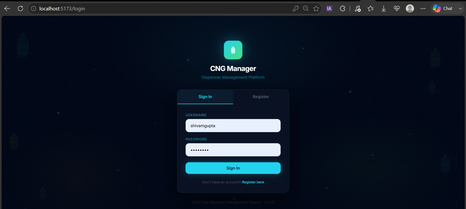
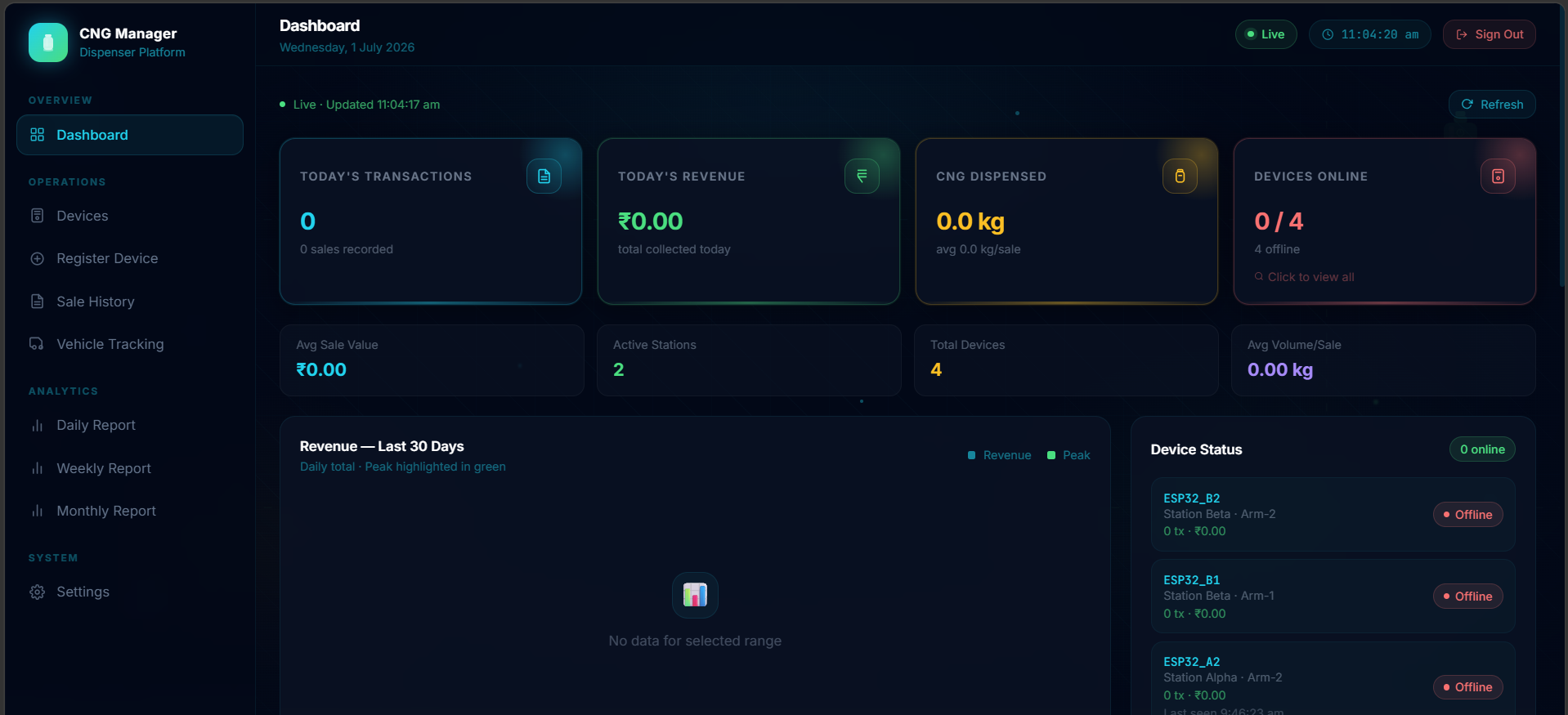
Dashboard: Live sale count, revenue today, active devices
Devices: All registered dispensers with online/offline status
Sale History: Every sale record with filters
Vehicle Tracking: Per-vehicle fill history and total spend
Daily Report: Day-by-day totals with CSV export
Weekly Report: Week-over-week revenue chart
Monthly Report: Monthly totals and trends
Settings: Account management
Firmware Configuration & Flash
7.1 — Understand the config.h File
Every ESP32 unit is flashed with the same sketch but a different `config.h`. The pre-built per-device configs are in `firmware/devices/`:
7.2 — Configure for Your First Dispenser
marked inside the file:
Step 1 — Select your dispenser brand (uncomment exactly one):
Step 2 — Set the unique device ID (change for every unit):
Step 3 — Set the Modbus slave address:
Step 4 — Set WiFi and API (same for all units at one station):
If you chose `DISPENSER_GENERIC`, also fill in the register addresses you found in Step 5.4:
7.3 — Flash the Firmware
1. Connect the ESP32 to your PC via USB.
2. In Arduino IDE:
- Tools → Board → select "ESP32 Dev Module"
- Tools → Port → select the COM port for your ESP32(Windows: `COM3`, `COM4`, etc. — check Device Manager if unsure.
- Tools → Upload Speed → `921600` (or lower if uploads fail)
- 3. Click Upload (→ arrow).
- 4. You may need to hold the BOOT button on the ESP32 while upload starts(only required on some boards without auto-reset circuitry).
7.4 — Verify on Boot
Open Serial Monitor at 115200 baud immediately after flashing.
You should see:
And the LCD shows: `CNG Ready [WiFi]` / `Press * to start`
Register the Devices in the Dashboard
The ESP32 firmware looks up its own MongoDB `_id` by calling `GET /api/devices/lookup/{DEVICE_ID}`. This only works if the device document already exists in the database.
8.1 — Check Seeded Devices
The `seed_devices.js` script (Step 6.5) already created 4 devices: `ESP32_A1`, `ESP32_A2`, `ESP32_B1`, `ESP32_B2`.
Verify them in the Devices page of the dashboard, or via the API:
8.2 — Add a Custom Device
If your dispenser has a different ID than the seeded defaults, add it via the dashboard Devices page (click "+ Add Device") or with the API:
The `deviceId` here must exactly match `DEVICE_ID` in `config.h`.
8.3 — Confirm Device Goes Online
After flashing and connecting to WiFi, the ESP32 sends a heartbeat PATCH every 20 seconds. Within 20 seconds of boot, the device card in the dashboard should show a green "online" badge.
Connect Everything: Full System Test
With hardware wired, backend running, frontend open, and firmware flashed, run a complete end-to-end test to confirm the entire pipeline works.
9.1 — Simulate a Sale from the Keypad
1. On the ESP32 keypad, press `*` → LCD shows `Enter Veh No: / >_`
2. Type a vehicle number using multi-tap:
- Press `4` once → `4`
- Press `5` twice → `5`, `5J` → wait 1.5 s to commit `J`
- Press `0` once → `0`
- Press `1` once → `1`
- Continue until you have e.g., `GJ01AB1234`
- Press `#` to confirm
3. LCD shows `Dispensing… / Veh:GJ01AB1234`
4. Trigger a Modbus transaction on your dispenser (do a short fill, or use `modbus_test.ino` → press `w` to write `REG_TX_STATUS = 0` after a real fill to simulate acknowledgment)
5. LCD shows `Sent! 5.20kg / Rs442 GJ01AB1234`
9.2 — Verify in the Dashboard
1. Open the Sale History page: the new sale should appear at the top.
2. Open the Dashboard: today's sale count and revenue should be updated.
3. Open the Vehicle Tracking page and search for `GJ01AB1234`: the fill history should show the record.
9.3 — Test WiFi Reconnect (Optional)
1. Disconnect the WiFi router briefly (5 seconds).
2. LCD briefly shows `CNG Ready[NoWiFi]`.
3. Reconnect the router — within 30 seconds the ESP32 reconnects automatically and
shows `CNG Ready [WiFi]` again.
4. Any sales made while offline are buffered (up to 10 records) and flushed
automatically once WiFi is restored.
Scaling to Multiple Dispensers
Each additional dispenser arm gets its own ESP32 unit. The process is identical to with two differences per unit:
10.1 — Create a Per-Device config.h
Copy `firmware/esp32_dispenser_client/config.h` and change only:
WiFi credentials and `API_BASE_URL` stay the same across all units.
The pre-made configs in `firmware/devices/` are ready to use:
Copy the contents of the right folder's `config.h` over the template in `esp32_dispenser_client/config.h` before flashing each unit.
10.2 — Each Unit is Independent
- Each ESP32 has its own RS-485 connection to its own dispenser.
- All units share the same WiFi and backend URL.
- The backend uses `deviceId` to distinguish sales from different arms.
- The dashboard shows all devices in a single unified view.
10.3 — RS-485 Bus Topology
Each ESP32 connects to **one dispenser only** (point-to-point). This is the simplest and most reliable topology. If your dispenser manufacturer already daisy-chains multiple dispenser heads on one RS-485 bus (common in 2-arm dispensers), you can use Modbus addresses 1 and 2 on the same RS-485 pair, but you'll need only one ESP32 with a modified sketch — contact the dispenser manufacturer for the register map in that case.
Troubleshooting
LCD shows nothing / all black squares
- Turn the small blue contrast potentiometer on the back of the I2C backpack.
- Verify SDA→GPIO21, SCL→GPIO22.
- Try changing `LCD_I2C_ADDR` from `0x27` to `0x3F` in `config.h`.
- Run an I2C scanner sketch to find the actual address.
Keypad keys not registering or wrong characters
- Re-check the row/column GPIO assignments against the physical keypad ribbon.
- Use a multimeter in continuity mode: pressing a key should short one row pin to one column pin.
- Pin 1 of the keypad (marked with a dot or arrow) is row 0.
Modbus: "No valid response" in modbus_test.ino
- Check A/B polarity — swap them if needed.
- Verify the RS-485 module DE/RE pins are bridged.
- Confirm the dispenser is powered and its Modbus port is active.
- Run baud scan (`b`) — your dispenser may use 19200 or 38400, not 9600.
- Check the dispenser manual for the RS-485 terminal location — some models labelit "COM" or have it inside a locked service panel.
ESP32 shows "CNG Ready[NoWiFi]" and never connects
- Confirm SSID and password in `config.h` are correct (case-sensitive).
- Check the ESP32 is within range of the access point.
- ESP32 only supports 2.4 GHz WiFi — if your router is 5 GHz only, it won't connect.
- If you changed `WIFI_RECONNECT_INTERVAL_MS`, ensure it's not set too short.
Serial Monitor shows "Device _id not found" or fetch fails
- Confirm the backend is running and reachable at `API_BASE_URL`.
- Verify the device was seeded: `node scripts/seed_devices.js`.
- Check the `DEVICE_ID` in `config.h` exactly matches the `deviceId` in MongoDB (case-sensitive: `ESP32_A1` ≠ `esp32_a1`).
- Test with `wifi_api_test.ino` → Test 2 will report if the device is missing.
Sales not appearing in the dashboard
- Check the backend terminal for incoming POST requests — each sale should print:`[hh:mm:ss] POST /api/sales`
- Confirm the POST returns HTTP 201 (check Serial Monitor: `[Flush] OK veh=...`).
- If HTTP 4xx, the `deviceId` in the POST body may not match any registered device.
- Refresh the dashboard — the SSE live update may not have connected; a manualrefresh will always show the latest data from MongoDB.
Sale shows wrong quantity or amount (e.g. 100× too large)
- The firmware reads values as integers × 100 (e.g., 5.20 kg is stored as 520).
- If your dispenser stores raw kg without the ×100 scale factor, divide the rawvalue by 1 instead of 100. Edit the `modbusReadTransaction()` function:
Backend won't start — "MongoServerError: connect ECONNREFUSED"
- Make sure MongoDB is running: `mongod --dbpath /data/db` (Linux/Mac)or start the MongoDB service in Windows Services.
- If using Atlas, confirm the `MONGO_URI` in `.env` is the full Atlas connectionstring including username, password, and cluster hostname.
"DEVICE_ID is not defined" compile error
This means you are compiling the main sketch without `config.h` present in the same folder. Make sure both `esp32_dispenser_client.ino` and `config.h` are in the same directory, and that directory is what you opened in Arduino IDE.
Operator Quick-Reference Card
Cut this out and post it at each dispenser station.
#Appendix: Generating Demo Data
To populate the dashboard with 30+ days of synthetic sales for a demo or presentation:
To export analytics reports to CSV files in the `dataset/` directory: