Cardboard Candy Vending Machine
by dariusfg in Craft > Cardboard
1035 Views, 4 Favorites, 0 Comments
Cardboard Candy Vending Machine

I built a cardboard candy vending machine for the Instructables 2025 Cardboard and Paper contest. It is capable of vending candy bars!
Supplies


Tools:
- Laser cutter
- Drill gun
- Hot glue gun
- Pilot hole drill (1/16" or equivalent, size is not critical)
- Arduino IDE (Software)
Materials:
- Cardboard 12" length of 2x4 (2 needed)
- Packing tape
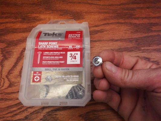
- 3/4" Lath screws (36 needed)
- Hot glue
- Arduino with 5V output. (Pretty much any will work, but I used an Arduino Uno.)
- A normally open momentary electronic button (Optional, if omitted, see first "Tip" on Tips section.)
- 1K Ohm resistor (Optional, needed for button)
- 2 male to male jumper wire (Optional, needed for button)
- 1 Electronic Breadboard (Optional, needed for button)
- 4 female to male jumper wires
- Stepper motor (28BYJ-48)
- Motor driver (ULN2003)
- Candy Bars!!! (No loose/baggy wrappers! See image.)
Note the button is optional. Videos and pictures use an electric button that is momentary (active when pushed down) with wire leads that connect to a breadboard.
Cutting Out the Platform


Cut two lengths of 2x4 lumber 12" long. The exact length is not critical, and scrap lumber works well so long as it is a standard 2x4.
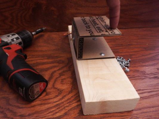
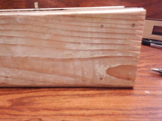
Place a piece of packing tape down one edge of each 2x4 (see image). This makes one edge of each piece slippery, to reduce friction.
Cutting the Cardboard

Using a laser cutter, cut the cardboard pieces. Patterns are supplied as LightBurn projects (.lbrn files) and DXF files (.dxf). If you don't use LightBurn, any laser cutting programs should be able to import DXF files.
The cardboard forms have two cut settings: "cut" and "half-cut". "Cut" slices all the way through the cardboard, and "half-cut" slices the top layer but does not cut all the way through.
Thus, a piece might have a "cut" edge along the perimeter, but one or more "half-cut" edges on the inside. Once the piece is cut, it is bent into shape, and the "half-cut" edges become a 90 degree hinge.
Be sure to use the power settings appropriate for your laser. For an 80 watt laser the following settings work well:
Cut: Speed 40 mm, Power 40%
Half-Cut: Speed 100 mm, Power 20%
Using a scrap piece of cardboard, test and verify that you are using the appropriate power settings for your laser.
Then cut out the following pieces:
- 4x Pusher
- 2x Hopper
- 4x HopperShim
- 2x Gear
- 1x GearPlate
- 3x GearBack
Installing the Motor

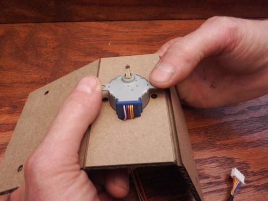


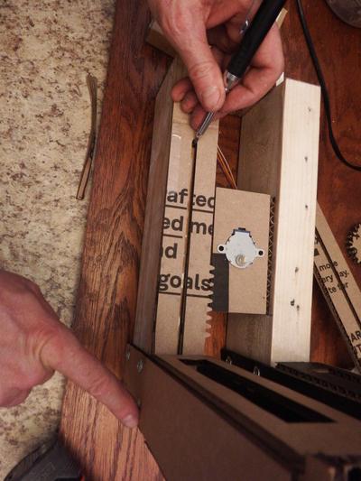
Push the stepper motor into the corresponding hole in the GearPlate so that the metal mounting holes are on top (see image). The motor should fit snugly.
Push two of the GearBack pieces onto the back side of the motor and glue in place to make a sturdy holder for the motor (see image).
Do not glue the two wings of the gear plate yet, these should bend freely (see image).
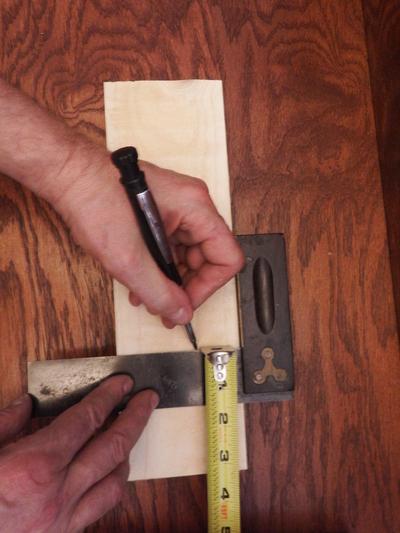
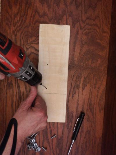
Using a pencil, mark a line across the 4" face of each 2x4, 3-1/4 inches from one end (see image). Note: This line is where the motor platform will go. In the videos we have moved this line an additional 2-3/4 inch for a total of 6 inches. Both the 3-1/4 inches and the 6 inches will work, we found the 6 inches to be easiest to work with should any calibration issues arise.
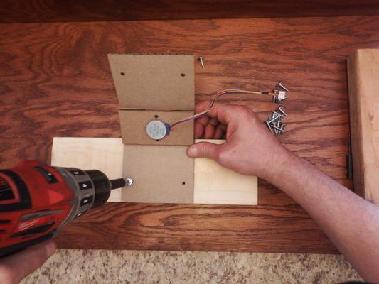
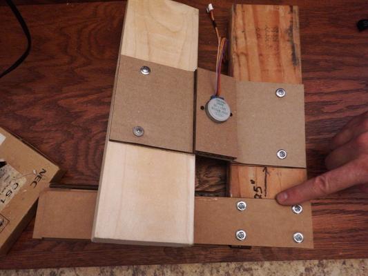
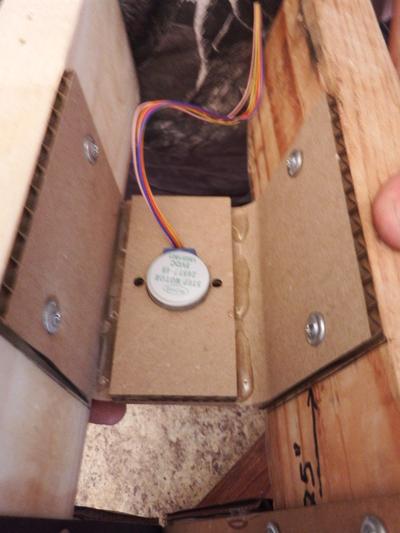
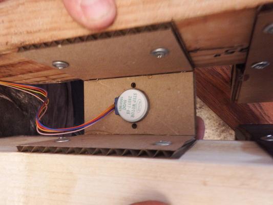
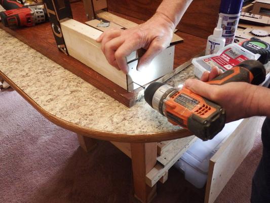
Place one wing of the GearPlate against one marked line, drill four pilot holes and install four lath screws as shown.
The gear plate is designed to match the height of a 2x4 and bring the motor to the correct height, so if you place the cardboard and lumber on a flat surface everything should line up.
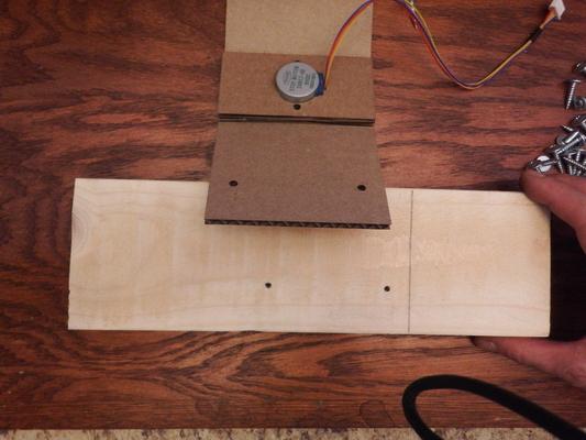
Place the other wing of the GearPlate against the marked line on the other 2x4, drill and attach as before.
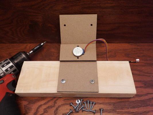
The GearPlate wings should still bend freely, with the lumber attached. They will be glued shut in a later step.
The gear plate should be behind the 3-1/4 inch line, and the top of the motor should be parallel to the taped edges, as shown.
Installing the Hopper
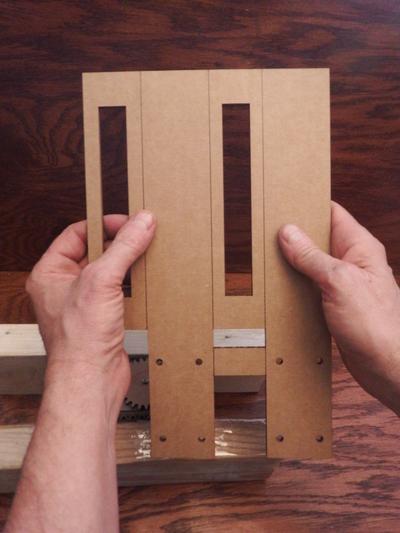


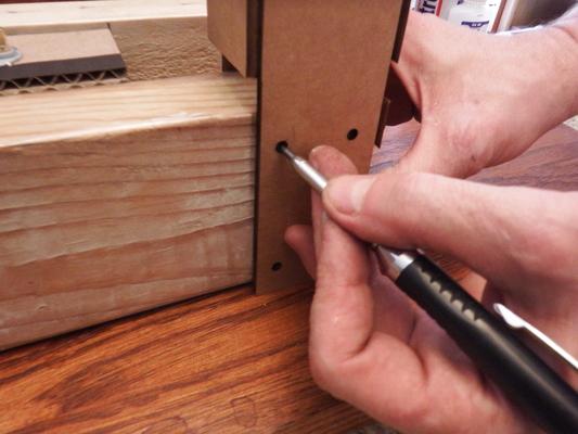


Take one Hopper cutout and bend it around the end of one 2x4 (see image). Mark and drill 8 pilot holes as shown, four on each side, then attach the hopper using 8 lath screws, four on each side.
Bend the fourth side of the hopper around to meet the first side and glue into place (see image).
The hopper is designed to fit the end of a standard 2x4, so if you place the board and cutout on a flat surface everything should line up.
Attach the 2nd hopper to the end of the second 2x4 board.
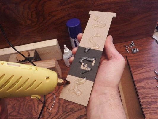
Insert two hopper shims into one hopper, one on each side, and glue into place (see image).
Glue two shims into the other hopper as well.
Install the Pushers


Make one thick pusher by gluing two pushers together.
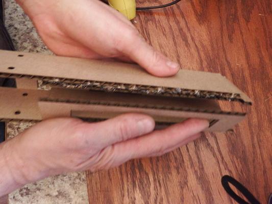
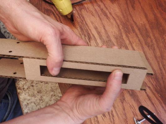
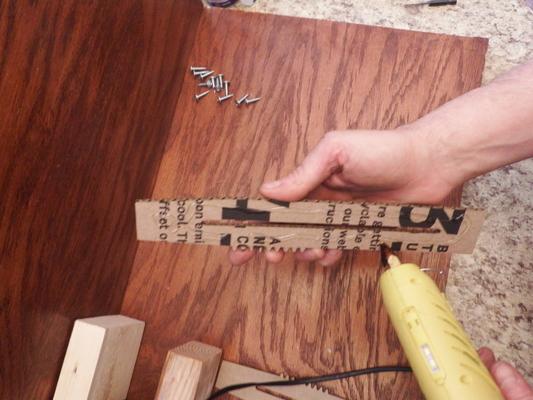
Place one pusher on the taped edge of the 2x4 with it's front end not quite in the hopper (see image), mark and drill a pilot hole at the forward end of the pusher slot.
Slide the pusher forward and into the hopper until the end reaches the end of the 2x4, then mark and drill a pilot hole at the rear end of the slot (see image).
Loosely screw the pusher to the 2x4 using two lath screws. Loosely!
Verify that the pusher slides easily forward and back, and is held in place by the lath screws.
Glue the GearPlate Wings
When the hoppers and pushers are installed, glue the GearPlate wings so that they don't bend.
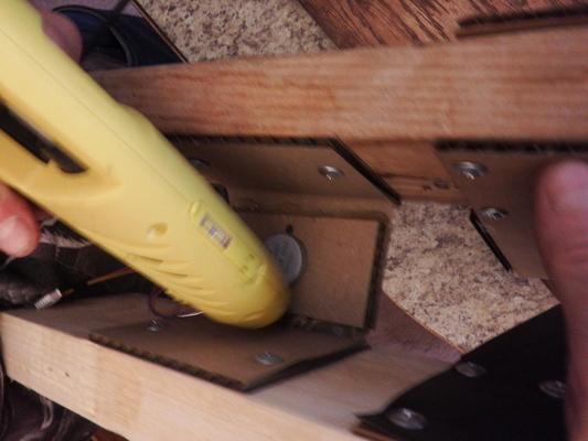
Using hot glue, run a bead down the inside corner of the GearPlate to lock everything into place.
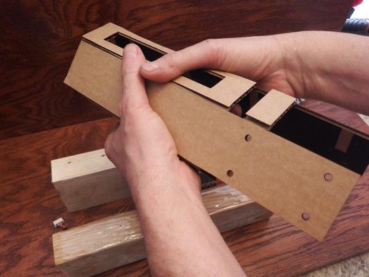
Glue the EndPlates

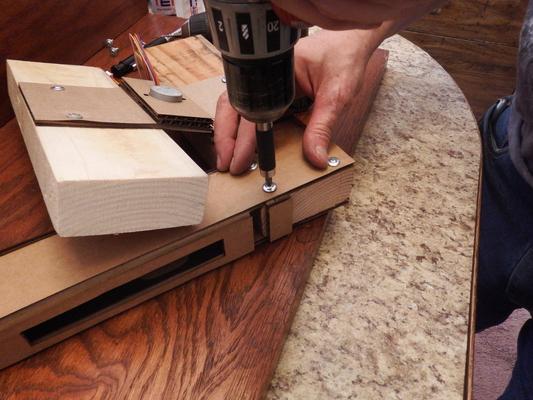
Mark, drill, and attach the end plates across the ends of both 2x4 pieces using eight lath screws, four for each end plate.
The end plates should lock the the entire assembly together to make a sturdy system.
Make and Install the Gear

0-step position: Position each pusher so that their backends align with the ends of the 2x4, this is your "0-step position."
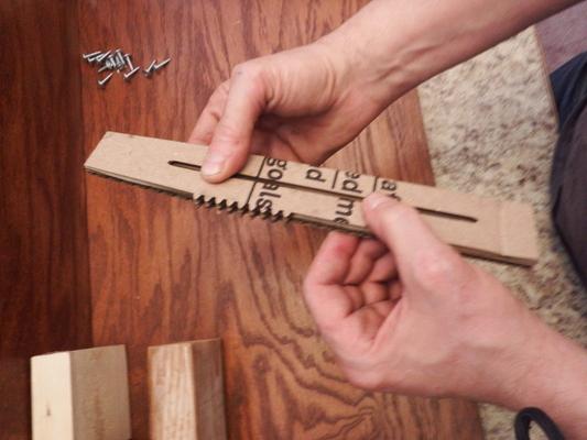
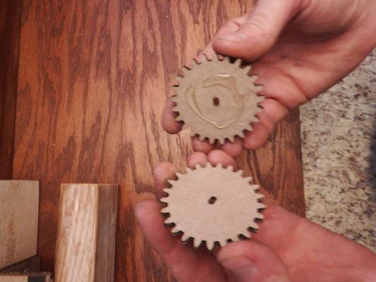
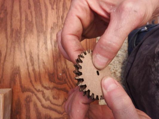
Glue two gears together to make one thick gear. Be certain the teeth line up before gluing.
Press the thick gear onto the motor shaft and cement in place using a liberal amount of hot glue.
Wire the Motor

Connect the motor to the motor driver, then use the male to female jumper wires to connect the motor driver to your Arduino (I used an Uno.) Follow the connection diagram provided.
The pins are labeled on the motor driver, and if you're using an Arduino Uno, the pins are labeled on the board as well.
- Connect the 5V pin of the motor driver to the 5V pin of the Arduino.
- Connect the GND pin of the motor driver to any GND pin of the Arduino
- Connect IN1 to DIGITAL pin 4
- Connect IN2 to DIGITAL pin 5
- Connect IN3 to DIGITAL pin 6
- Connect IN4 to DIGITAL pin 7
If you are using a button, be sure to follow the provided wiring diagram:
- Connect one of the button leads to the 3.3V pin. Do not connect it to the 5V pin!
- Connect the other lead of the button to your breadboard.
- Connect your 1K Ohm resistor to the same row as the button lead, and put the other end of the resistor into a different row.
- Connect a male to male jumper from the row shared by the button lead and resistor to DIGITAL pin 2.
- Connect a male to male jumper from the other end of the resistor to any GND pin on the Arduino.
Program the Arduino

Download the provided .ino file, and put it in a folder named Cardboard_Vending_Machine - programming will otherwise fail.
Open the .ino file with the Arduino IDE.
Plug in your Arduino board to one of the USB ports of the computer running Arudino IDE.
Go to Tools->Port, and select the serial port that matches your board (see red boxes in image.)
Click the check mark and right pointing arrow buttons to create your program, and then upload it to the board (see orange boxes in image.) Your board should be programmed and ready to go!
Note: You can communicate with the board via the Serial Monitor (see green box in image.) See the Tips section at the bottom for more information.
Downloads
Dispense the Candy
Fill each hopper with 20 bars of candy, making sure each bar lies flat inside the hopper, and power on the Arduino.
If you are using a momentary button to vend the candy, go ahead and press it!
Enjoy!
Tips

Your machine is complete! This section is in case you run into any problems.
Tip - No button: You can manually trigger vending by communicating to your Arduino over serial. To do this make sure your Arduino is connected via USB to your computer. Open up Arduino IDE, and make sure your port is selected to your Arduino (Tools->Ports, image available on step 10.) Now open the Serial Monitor, by going to Tools->Serial Monitor. You should see a window pop up named "Serial Monitor" like in the image provided. To issue a manual vend enter a single asterisk (*) and a number, for example entering "*1" (no quotes) will issue one vend. "*100" will do 100! To stop vending enter "*0".
Tip: If the machine struggles to push candy fully out the hopper you might need to change your 0-step position by setting the pushers a bit closer or further from the hoppers relative to the back of the 2x4. After doing this, power cycle the Arduino to re-establish the "0-step position.
Tip: If the machine ever jams, and loses track of it's position, you can manually drive the motor from the Arduino IDE. To do this you will want to connect to the Arduino over the Serial Monitor (see first step.) Then enter a number from -1000 to 1000 to manually move the motor. Depending on the jam, you might need to enter values below -1000 or over 1000, just be sure to overshoot this boundary by steps of -200 or 200 at a time to avoid over working the motor.
Tip: If the hopper is empty, and the motor struggles to move the pushers, consider putting hot glue into the gear teeth of the motor gear and the pushers. Doing so will strengthen the gear teeth and fill any empty spaces that might be causing problems. Be mindful of excess hot glue oozing out of the gear teeth, as it will obstruct the path of the motor gear. If the glue is not too hot use a piece of scrap cardboard to wipe the excess glue. Otherwise wait for the glue to harden, and carefully cut the excess off.