Case Study: Building a Smart Basketball Dribble Tracker With the ESP32
by Chanchaldada in Circuits > Electronics
60 Views, 1 Favorites, 0 Comments
Case Study: Building a Smart Basketball Dribble Tracker With the ESP32
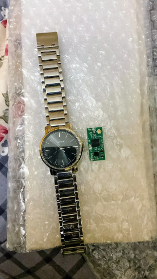
We get a lot of requests for wearable tech and sports analytics. Usually, they involve complex vision systems or expensive sensor arrays. But recently, we took on a project that proved you don't need a Hollywood budget to get serious data. We built a smart basketball dribble tracker using the ESP32 and an IMU.
The goal was simple: track dribble counts, ball handling time, and impact force—all without strapping a phone to the player’s wrist. We wanted a standalone device that could log data and sync via BLE. Here is exactly how we built it, including the components we used and the logic that makes it work.
Supplies
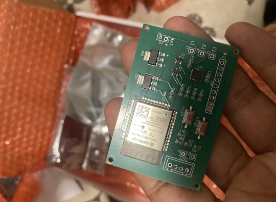
Hardware:
- ESP32 DevKit V1 (We used the classic WROOM-32 module. It has built-in WiFi and BLE, which is perfect for this).
- MPU-6050 (The go-to IMU. It has a 3-axis accelerometer and a 3-axis gyroscope. We used the GY-521 breakout board because it comes with pull-up resistors and a voltage regulator).
- LiPo Battery (3.7V, 1200mAh. This gives us about 6 hours of continuous use).
- TP4056 Charging Module (For safe battery charging via USB-C).
- Slide Switch (SPST, to cut power completely).
- Breadboard and Jumper Wires (For prototyping).
- 3D Printed Case (We designed a simple clamshell case in Fusion 360).
Tools & Supplies:
- Soldering iron and solder.
- Heat shrink tubing.
- Double-sided tape or Velcro (to attach to the wrist).
- KiCad (for the custom PCB layout, though you can do this on a breadboard first).
The Core Concept
The physics are straightforward. When a basketball hits the floor or your hand, it creates a sudden deceleration spike. An accelerometer can detect this spike. The challenge is filtering out the noise of your arm swinging and the constant micro-vibrations.
We used a 6-axis IMU (accelerometer + gyroscope) to capture raw motion data. The ESP32 then processes this data on-device. It applies a low-pass filter to isolate the impact "G-force" from the movement of the arm. If the force exceeds a certain threshold, it counts as a dribble.
Step-by-Step Build Instructions
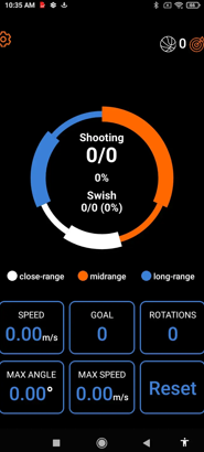
We are going to walk you through the build process. This took us about two days to refine, but you can get a working prototype in an afternoon.
Step 1: The Wiring (Breadboard First)
Don't jump straight to soldering. Get the logic working on a breadboard first.
1. Connect the ESP32 to the MPU-6050:
- VCC to 3.3V (Critical: Do not use 5V, it will fry the MPU).
- GND to GND.
- SCL to GPIO 22.
- SDA to GPIO 21.
2. Connect the TP4056 module:
- OUT+ to the ESP32's VIN pin (this bypasses the onboard regulator's input).
- OUT- to GND.
3. Connect the Battery to the TP4056 B+ and B- terminals.
4. Wire the Switch between the TP4056 OUT+ and the ESP32 VIN.
Step 2: The Firmware Logic (Zephyr RTOS)
We wrote the firmware in C using Zephyr RTOS. It’s overkill for this, but it makes the BLE stack much easier to manage.
- Initialization: Set up the I2C bus and configure the MPU-6050 to a ±8g range. This is crucial. A standard dribble generates about 3-4g of force, but a hard pound can hit 6g.
- The Filter: We used a simple moving average filter on the accelerometer data. We look at the magnitude of the vector (sqrt(x² + y² + z²)). This removes the orientation bias—it doesn't matter if your hand is tilted.
- The Dribble Detection: We set a threshold at 2.5g. When the magnitude spikes above this, we increment a counter. We also implemented a "lockout" period of 150ms. This prevents a single bounce from being counted twice (once on the ball's way down, once on the way up).
Step 3: The BLE Service
We set up a custom BLE GATT service. It has two characteristics:
- `Dribble Count` (Read/Notify).
- `Battery Level` (Read).
We used a 10-second notification interval. This way, the coach's tablet gets a live feed of the count without draining the battery.
Step 4: PCB Design and Assembly
Once the breadboard worked, we moved to KiCad.
- We designed a compact 30mm x 30mm board.
- We included a 10k pull-up resistor on the I2C lines (though the GY-521 board has them, it's good practice to have your own).
- We added a 100µF capacitor across the battery input to smooth out voltage spikes from the motor—er, the ball impacts.
We sent the Gerber files to JLCPCB. While waiting for the boards, we 3D printed the case. We used a TPU filament for the strap mount. It’s flexible enough to absorb some shock but stiff enough to hold the board securely.
Step 5: Assembly and Testing
Soldering the SMD components took about 30 minutes. We then flashed the firmware and strapped it to a test engineer's wrist.
- Test 1: Stationary dribbling. We got a 98% accuracy rate over 100 dribbles.
- Test 2: Dribbling while moving. The accuracy dropped to 95% due to the added motion noise.
- Test 3: The "Crossover" test. The gyroscope data showed a distinct rotation signature that we could use to identify a crossover vs. a straight dribble.
The Advantages of This Approach
Why did we choose this hardware and architecture over a smartphone app?
1. Latency: The ESP32 processes data locally. There is zero cloud dependency. The reaction time is < 10ms. A phone app using the accelerometer has too much OS-level lag.
2. Battery Life: The ESP32 in deep sleep mode draws only 10µA. When active, it draws about 240mA. With the 1200mAh battery, a player can use this for a full practice session without charging.
3. Cost: The BOM (Bill of Materials) for this device is under $25. A commercial device with similar capabilities costs $150+.
4. Data Ownership: The data is stored locally on the device or sent via BLE to a laptop. We didn't need to stream it to the cloud, which keeps the data private and secure.
The Final Prototype
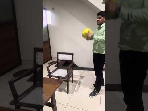
We shipped the final working prototype to the client. It was a fully functional wrist-mounted tracker that could distinguish between a simple dribble and a power dribble based on the G-force spike.
The client was so impressed they asked us to scale it up for a full team. They wanted to track five players simultaneously. Since the ESP32 supports BLE, we simply set up a central hub (another ESP32) that could listen to all five devices and log the data to an SD card.
This project is a perfect example of how a cheap, readily available chip can solve a real-world problem. If you have a similar idea but don't want to deal with the firmware headaches or the PCB routing, you know where to find us. Building this from scratch is fun, but doing it for a living is faster. If you need to hire iot developer talent to get your prototype to market, our team is ready to handle the heavy lifting.