Cerberus: Obstacle Avoiding Robot With Mecanum Wheels
by George_Andreou in Circuits > Robots
120 Views, 1 Favorites, 0 Comments
Cerberus: Obstacle Avoiding Robot With Mecanum Wheels
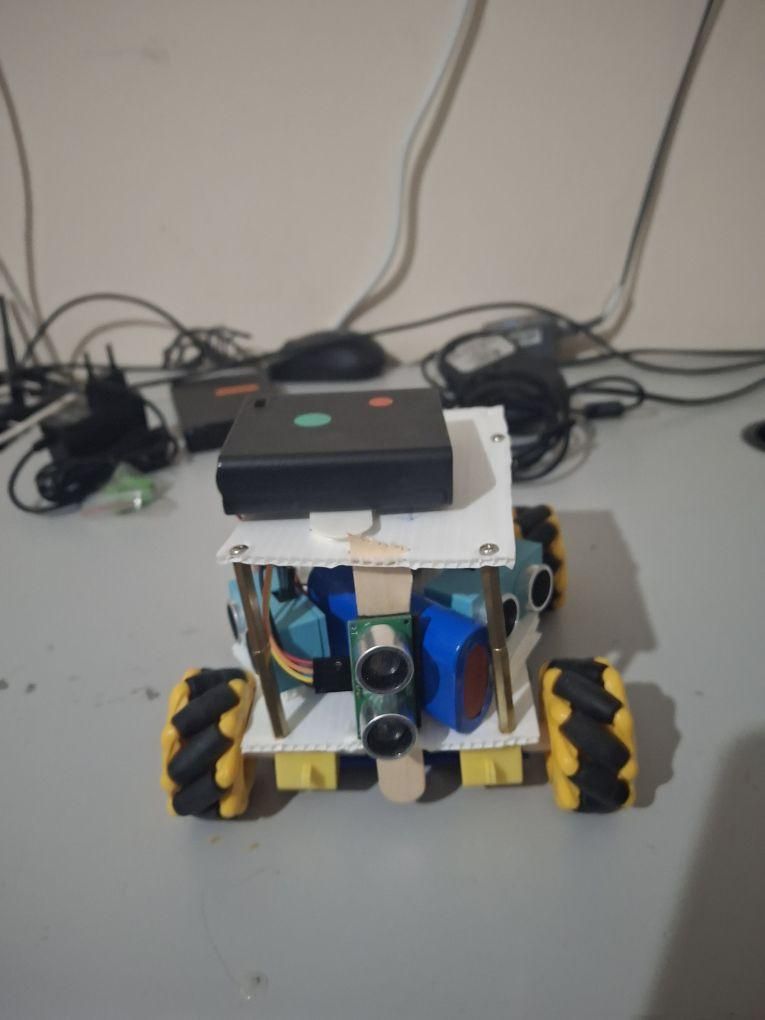
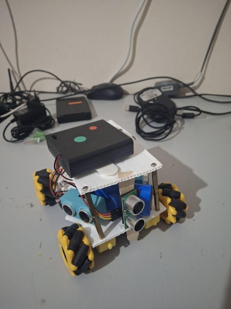
I made this robot in order to compete in the folkrace challenge of the "Robotex Cyprus" competition. Basically the robot must complete as many laps of the track as possible, while also avoiding walls, obstacles and other robots it may find in its way. I thought this was the perfect project to use some mecanum wheels I had lying around.
Turns out it avoids obstacles well enough and we won first place in that challenge, so I decided to share it so others can build upon this design.
The robot is named "Cerberus" due to its three heads, the three ultrasonic sensors, which look a little bit like the mythological dog with the same name.
Below I also have a link to the rules of the challenge. They are for the international version instead of the local one, but they are pretty much the same:
https://robotex.international/folkrace/
Basically there is a ~1 meter wide walled track in the form of a closed loop, usually also with some form of tunnel and bridge. Along the wall there are protruding obstacles that can easily trap a robot that follows the wall too closely, while in the middle of the track there are sometimes pillars that can also slow the robot down. The robot that completes the most laps in the time given is the winner.
In our case, our robot was slower in comparison to others, mostly because I set the speed to a little over the half to play it safe. However, its algorithm combined with the properties of the mecanum wheels enabled it to easily avoid obstacles that were more difficult for other robots, while also staying on the right path(not going in reverse to the trajectory of the track), resulting in its success.
The robot's logic:
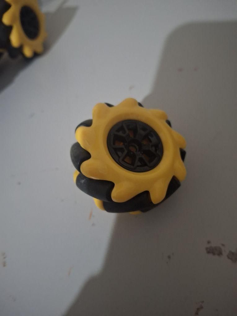
Mecanum wheels use rollers instead of tires to enable a robot to move in any possible direction.
- When an obstacle is detected some distance on the front: The robot avoids it by moving diagonally in the direction with the most space.
- When the robot gets dangerously close to an obstacle/hits on the front: The robot backwards a little and then rotates using its rear as the axis, only using its front wheels, in the direction with the most space.
- When the robot gets too close to a wall: The side sensors detect the wall and the robot stops one of its rear wheels in order to steer away from the wall
Supplies
- Adafruit Feather RP2040 (https://www.adafruit.com/product/4884), but theoretically any circuitpython compatible feather will work.
- Motor controller featherwing (https://www.adafruit.com/product/2927)
- 3 x Ultrasonic sensor RCWL-1601 (https://www.adafruit.com/product/4007). Completely compatible with the HC-SR04 but rated for both 5V and 3V, so works without the need for resistor. Theoretically, the HCSR04 could be used too, but with the necessary adjustments.
- Half-Size Breadboard (https://www.adafruit.com/product/64). A more permanent veroboard or protoboard can also be used, but I decided on a breadboard to make future adjustments easier.
- 4 x TT Gearbox DC Motors (https://www.adafruit.com/product/3777). I used four of them in order to have full freedom of movement.
- Mecanum Wheels (https://www.adafruit.com/product/4990). You will need 2 Left and 2 Right wheels for full movement.
- Li-Ion Battery Pack 4400 mAh(https://www.adafruit.com/product/354). Used to power the feather. Other similar rechargeables would probably work too.
- 4AA Battery Holder with switch(https://www.adafruit.com/product/830). Used to power the motors and their controller. Its switch is used as an on/off switch for the purposes of the competition.
Chassis
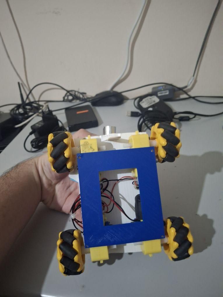
For the chassis you can use just about anything that can fit the 4 tt motors, the 3 sensors and the electronics.
In my case, I 3d printed a version of the chassis designed by earldaniph for the Mechamaven platform(https://www.instructables.com/MechaMaven-the-Educational-Robot-Explorer/), which I modified to fit the size restrictions of the competition. Of course, any other 3d printed chassis that fits 4 tt motors can be used.
In order to have a better space for the breadboard, controller and sensors, I added some coroplast on top of the 3d printed carriage.
The motors with the mecanum wheels were then screwed on the 3d printed chassis.
Sensor Wiring
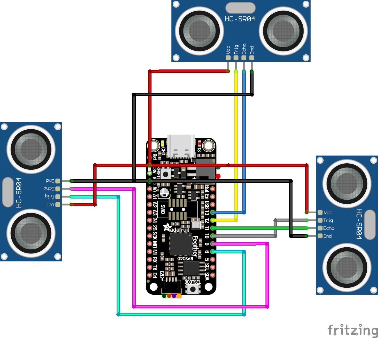
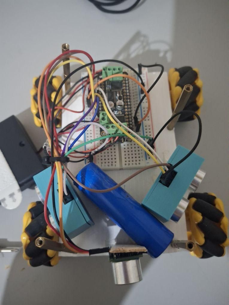
After we have a chassis we need to wire the 3 sensors. The two side sensors are mostly detecting the presence of walls, while the front sensors is used to avoid obstacles in the path.
As shown in the above fritzing sketch, the pins of each sensor are connected as detailed below:
Because the Feather's pins will be covered by the featherwing, I used longer headers with the "male" side attached to a breadboard and the "female" side attached to the featherwing. The sensors were connected to the feather through jumper wires to the breadboard.
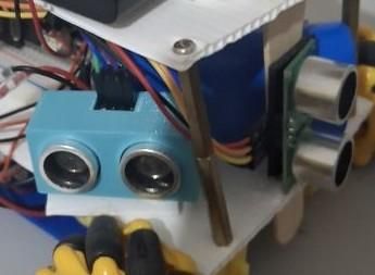
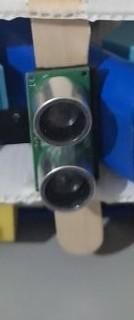
To fix the sensors to the chassis I used 3d printed RCWL mounts for the side sensors(https://www.thingiverse.com/thing:4749179), attached through double faced tape, while the front sensors was attached on a wooden stick I wedged through a cut on the coroplast. The front sensor was attached vertically instead of horizontally, enabling it to better detect thinner obstacles like pillars.
Motors
.jpg)
The motors are connected using the screw terminals of the featherwing. As for their numbering, the terminals are connected to the motors as shown below:
M1: Front left
M2: Front right
M3: Rear left
M4: Rear right
Powering the Motors and the Feather
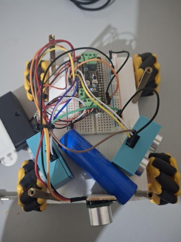
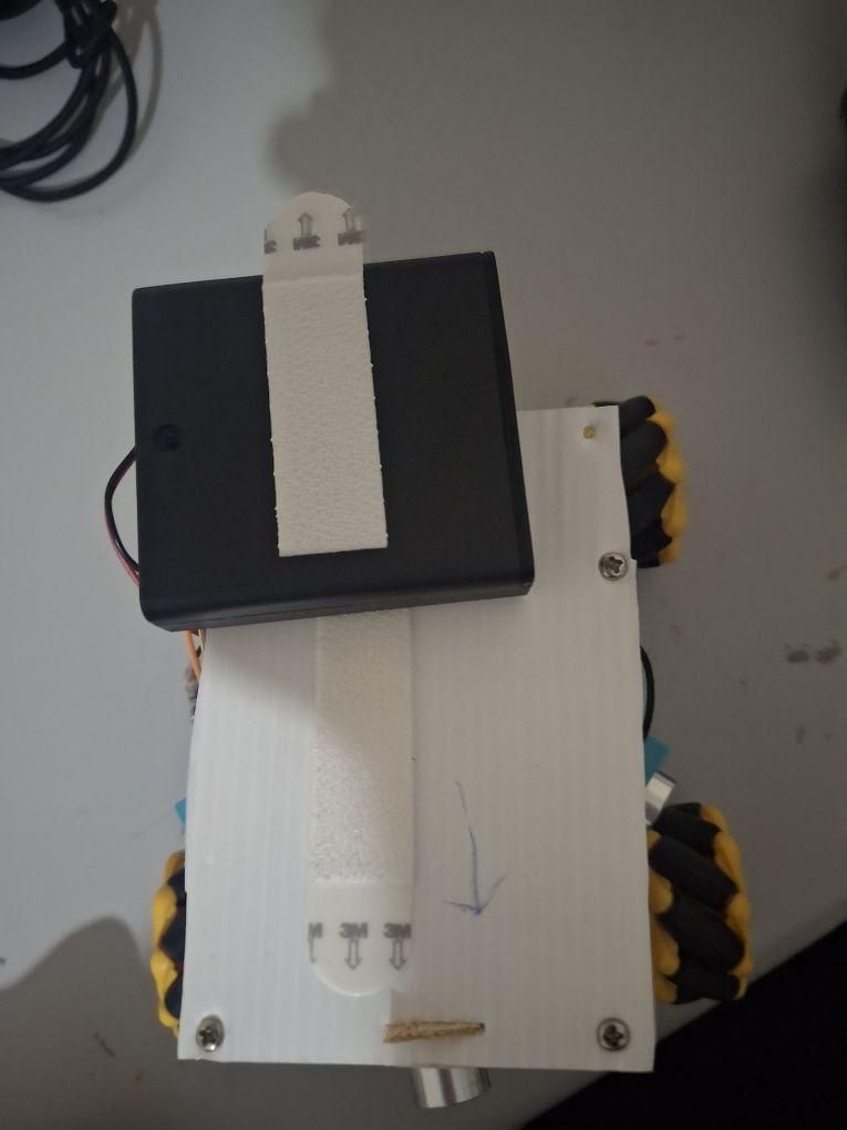
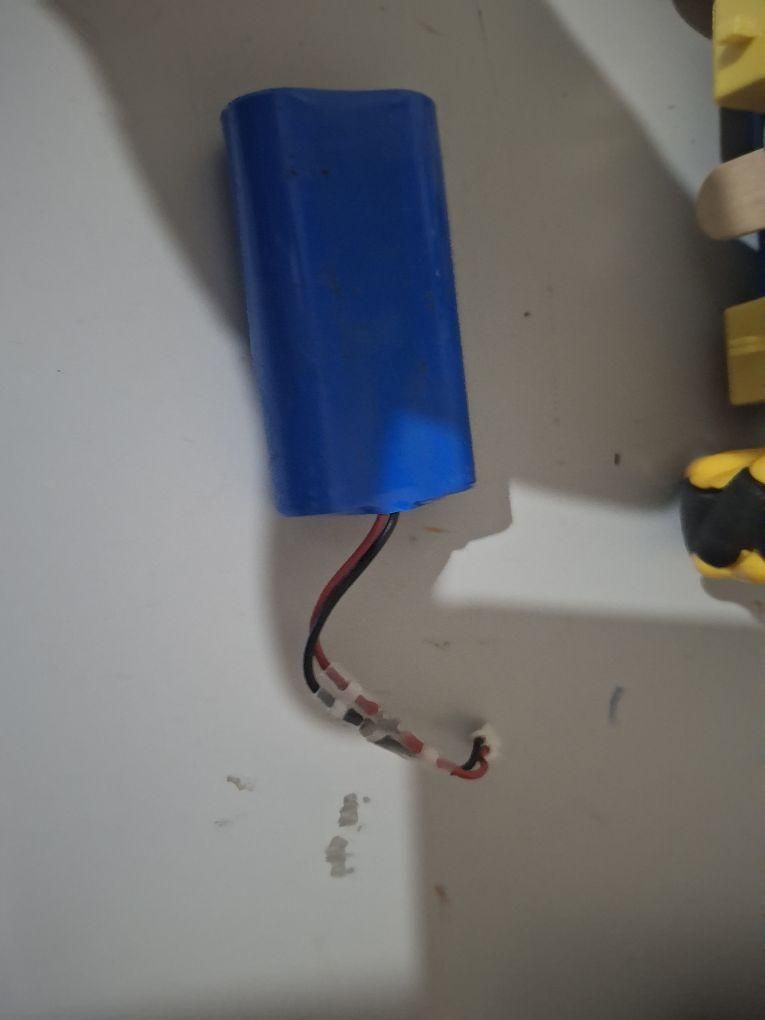
The robot uses two separate battery packs, one for the feather and one for the motors and their controller.
The feather is powered through the Li-Ion battery pack, connected through its JST connector. The feather board has its own charging circuit, so the type C port can be used to charge the battery connected to the JST connector. In my build, I placed the Li-Ion between the sensors and the breadboard, making sure the JST port is accesible in order to easily disconnect the battery.
As for the motors, they are powered through a 4AA battery pack connected through the featherwing's screw terminal. To attach the battery pack to the robot, I screwed another layer of coroplast on top of the robot using long metal spacers. The battery is attached on the top of the second layer using a "command strip", but some double faced tape can also be used.
The battery pack's built in switch acts as the on/off button of the robot during the competition. Basically, the Li-Ion stays always connected, enabling the feather to run the program, while the user turns the switch to "on" when the referee gives the signal, so that the motors power up and start responding to the loop.
Programming the Avoidance Algorithm
The robot's algorithm is written in circuitpython, a python derivative for microcontrollers (https://circuitpython.org/).
In order for the program to function, it also uses some libraries and dependencies from the circuitpython library bundle made by adafruit (https://github.com/adafruit/Adafruit_CircuitPython_Bundle). The libraries copied into the controller's "lib" folder are:
- adafruit_motor
- adafruit_register
- adafruit_hcsr04.mpy
- adafruit_motorkit.mpy
- adafruit_pca9685.mpy
Below is a breakdown of how the robot's programming works:
First we import the needed libraries. For the sensors, the hcsr04 library can be used, since the sensors are pin compatible with the hcsro04. The motorkit library is the library used for most motor controller add ons made by adafruit.
Then we set the names for the motors and sensors. The pins for each sensor are specified in this step. I also created a variable for the motor's speed, it can take any value from -1 to 1, so that I can more easily change it later.
Any possible moves the robot can make are defined in the above code. I have even included movement options for moves that aren't used in the main loop, just for possible future use.
More specifically, the robot can:
- Move forwards and backwards
- Strafe left or right (stleft/right)
- Move forward diagonally left or right (dgleft/right)
- Take a turn to the left or the right while moving, in order to avoid walls (turnleft/right)
- Rotate its body using its rear end as the axis of rotation (rotleft/right)
Now let's break down the main loop
If the front sensor detects an obstacle within the specified distance, the robot evades it by moving diagonally in the direction that has the most space available, as detected by the side sensors.
If the robot gets too close to an obstacle or wall in the front, it then goes backward a little to have more clearance, and the rotates depending again on which side has the most available space.
The above is used to help the robot stay centered on the track by avoiding getting too close to the wall. When the side sensors detect the wall in the given distance, the robot turns a little while still moving forward, by stopping one of its rear motors.
Should the robot get too close to either wall on its side, then it avoids it by moving diagonally in the opposite direction and then rotating a little due to the circular shape of the track.
The code, is open source under the GPL, and can be found in my git repository: https://git.theo-andreou.org/George_Andreou/Robotex-Folkrace
I have also included a program to test the sensors and print their values, and the fritzing wiring diagrams.
Finished!
After finishing the build and flashing the code, the robot is now ready to race and avoid obstacles.