Cereal Box Robot Using Cricut Explore to Cut Chassis and Wheels
by mrvigil in Circuits > Robots
3635 Views, 22 Favorites, 0 Comments
Cereal Box Robot Using Cricut Explore to Cut Chassis and Wheels

I am a middle school science teacher who also runs maker camps for kids in the summer. I am also the robotic club advisor for my school. We primarily use Lego NXT Mindstorm robots, but have been beginning to use arduinos for our robot competitions. In an effort to cut costs, I have been trying out different materials to make robot chassis and have decided to use a Cricut Explore to cut out wheels and chassis from cereal boxes. While wheels came out fine, the chassis was to flimsy, but this could be fixed by using more layers. (I used two.) I have also used foam board which I have had great success with, but just wanted to see what I could do with cereal boxes.
Create or Download Template for Cricut to Use to Cut Out Chassis

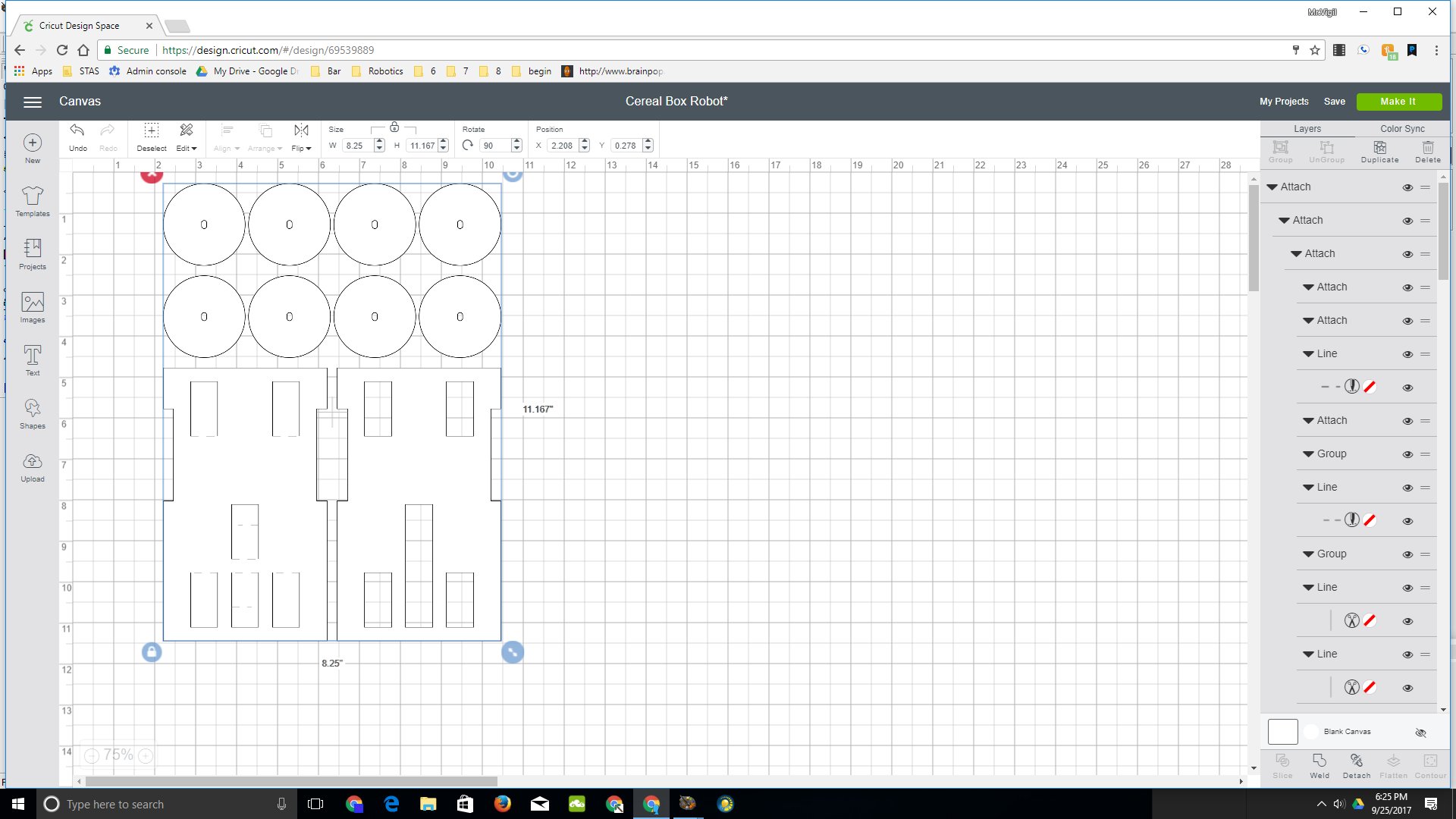

You can use this design by logging in to Cricut account:
Measure Box So That You Can Make Sure It Is Big Enough for Cricut Template.


Cut box into sections and then measure size of biggest section to make sure you have room on your cutting surface to cut your template.
You Might Have to Rearrange Your Pieces to Get Them to Fit.

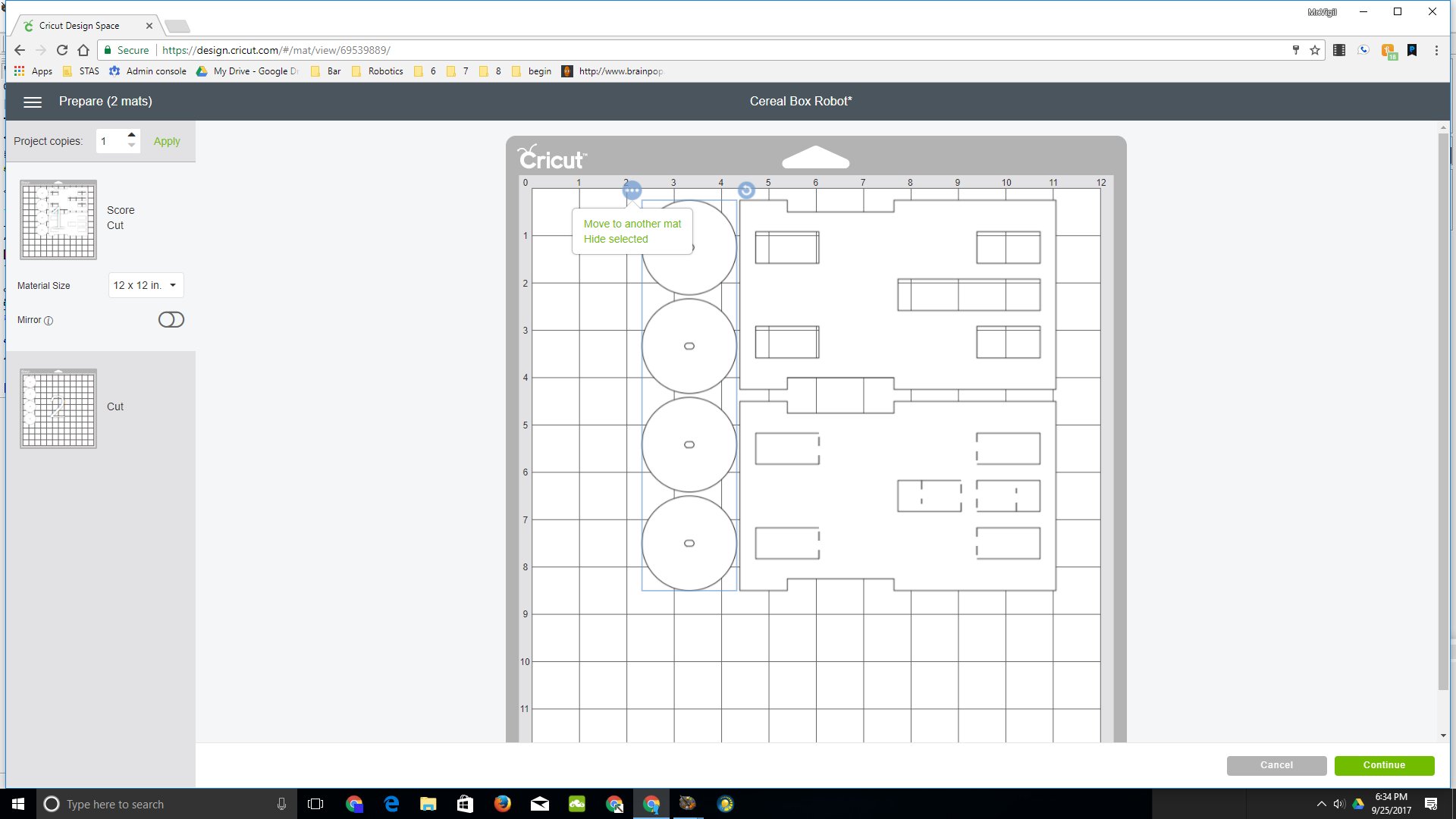

You can move pieces either on the mat preview or move them in program by detaching them and reattaching them in a different configuration.
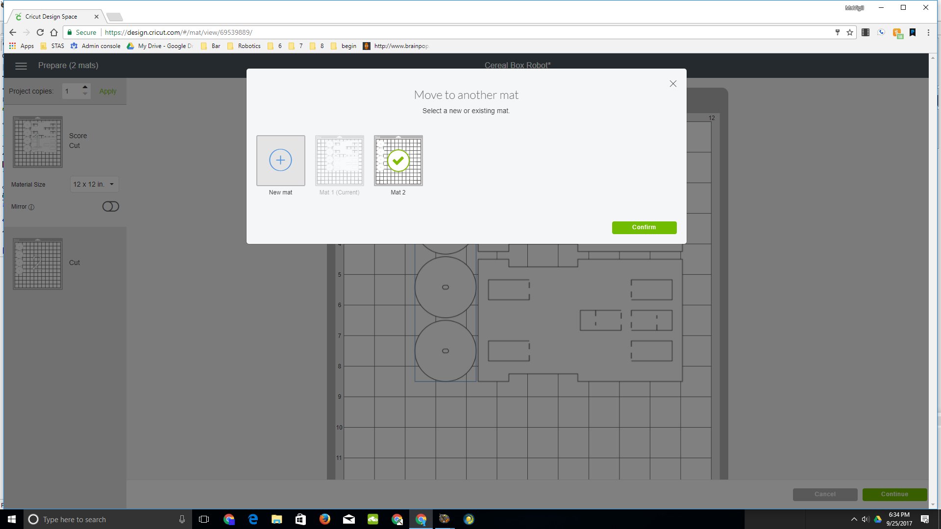
If You Can't Get Them to Fit, Then You Can Move Pieces to Another Mat.
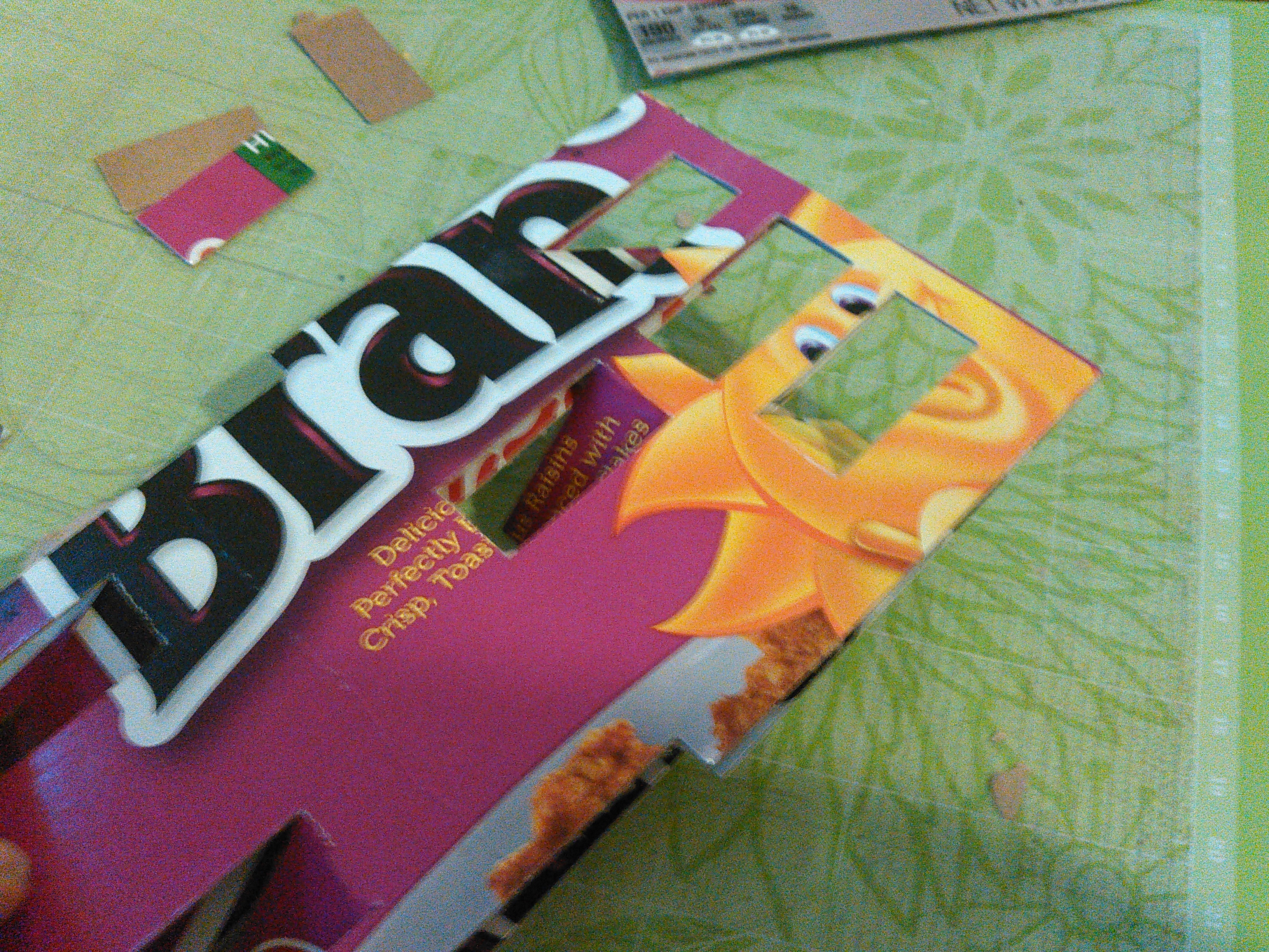
Once Done With Cutting, Remove Carefully From Cricut Mat.


Put Top and Bottom Pieces Together.


They should fit and tabs should line up. You may glue pieces together if you want.. this may help with rigidity.
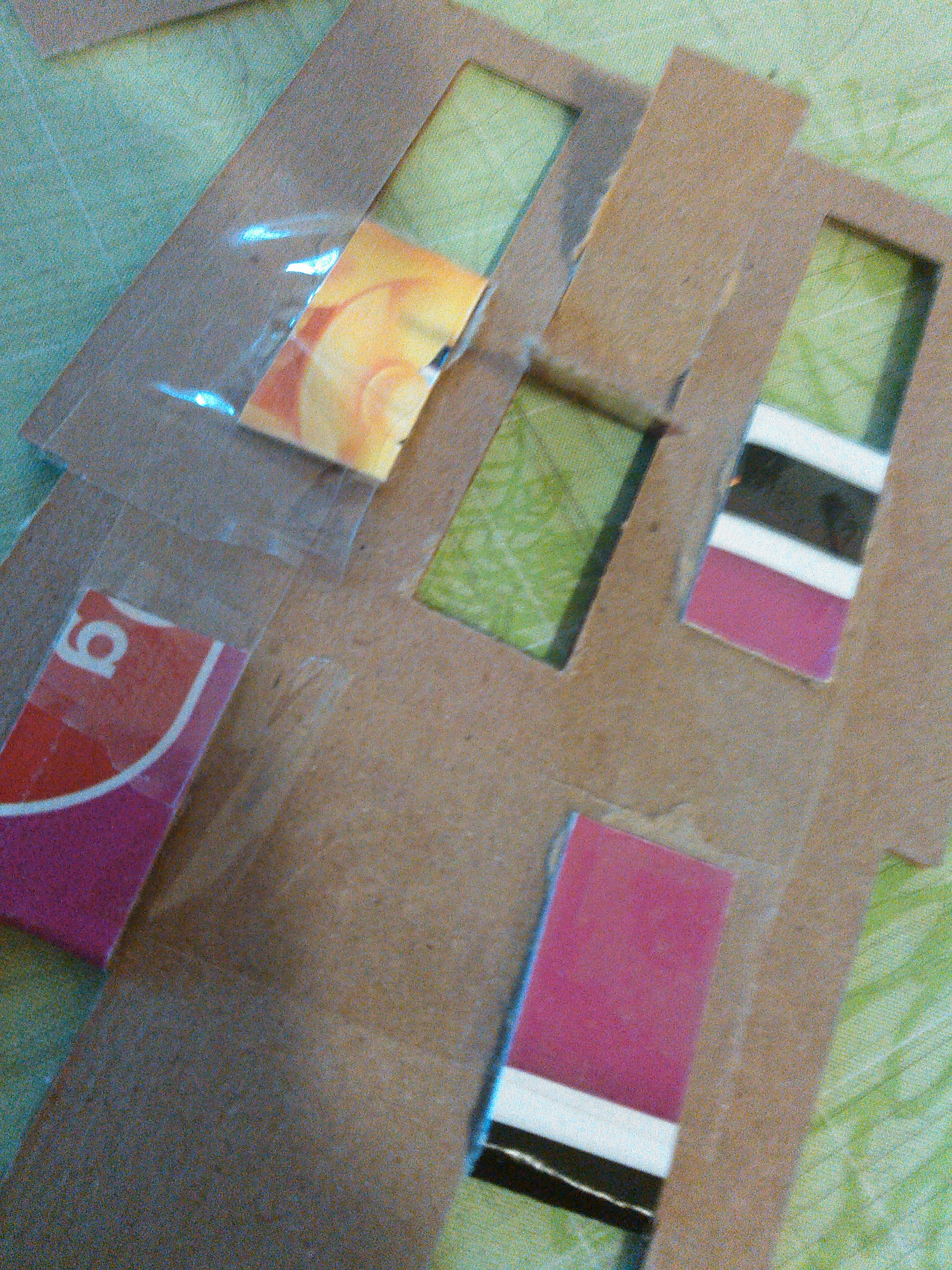

Tape or glue down flaps to complete chassis.
Complete Wheels and Attach.


I used 4 circles stacked up for each wheel and pieces cut out from an old bicycle inner tube. I aligned them on a the motor shaft, then I stretched a section of the inner tube over the wheels to hold them together. The wheels were then attached to the shaft and hot glued in place.
Solder Wires to Each Motor and Then Use Hot Glue to Prevent Shorts and Cable Strain.


Hot Glue Motors to Bottom of Chassis, Feeding Wires Up Through Cut Out Hole.


Connect Wire Leads to Motor Driver and Motor Driver to Arduino
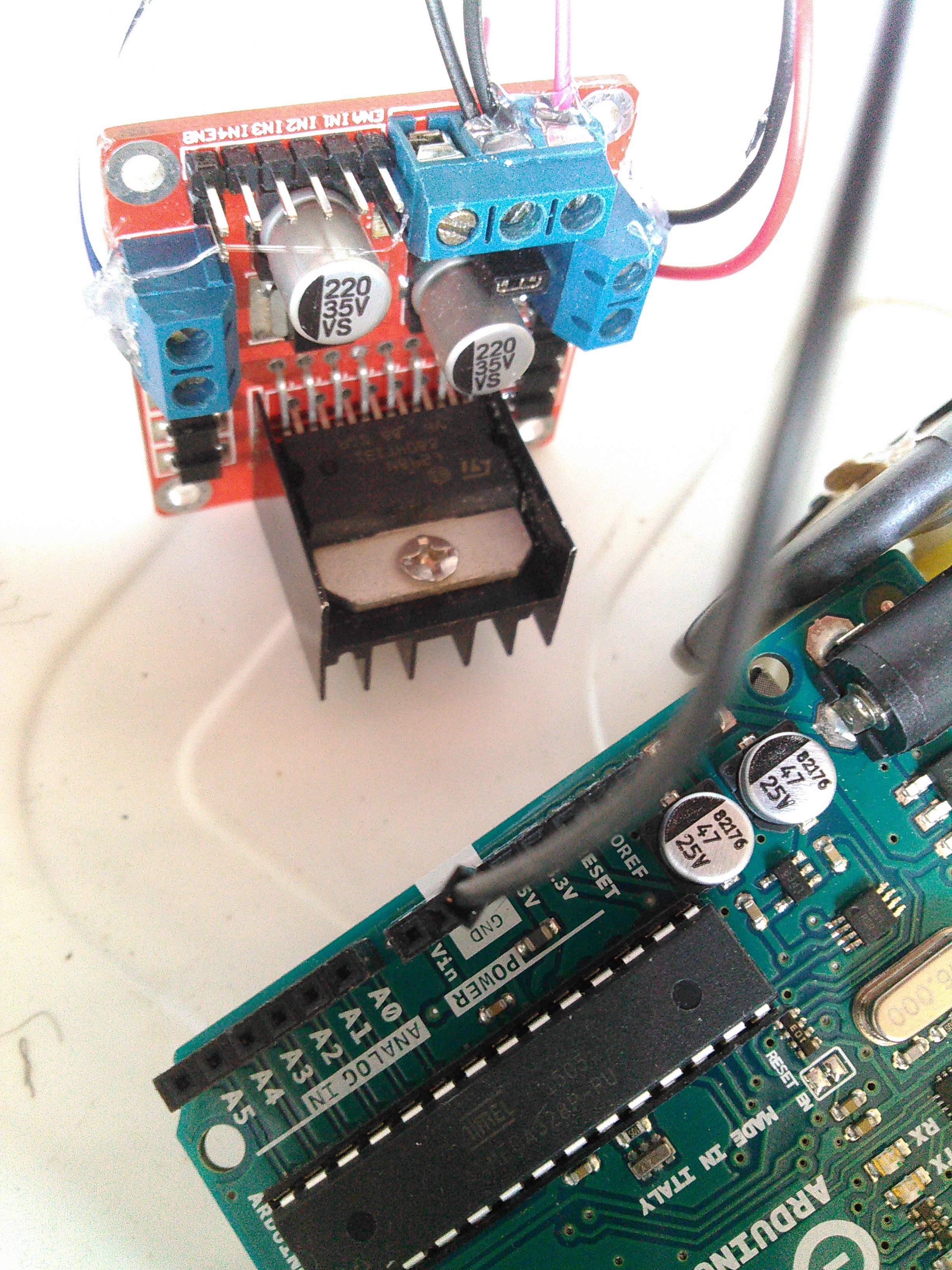


Don't forgot to use common ground for motor driver and arduino.
I used hot glue to help lesson cable strain and also prevent shorts.
Using Jumpers, Connect Motors to Driver Board


Connect Motor Wires to Motor Driver.

Connect Motor Driver to Arduino - I Used Pins 10,11,12,13

Upload Code to Arduino (need to Figure Out Which Motor Goes Which Way:
/* connect motor in1,in2,in3,in4 to arduino pins 10,11,12,13.
Connect ena, enb to pins 5 and 6
*/
int m1=10;
int m2=11;
int m3=12;
int m4=13;
int s1=5;
int s2=6;
void setup() {
 pinMode(m1,OUTPUT);
 pinMode(m2,OUTPUT);
 pinMode(m3,OUTPUT);
 pinMode(m4,OUTPUT);
 pinMode(s1,OUTPUT);
 pinMode(s2,OUTPUT);
 digitalWrite(s1,1);
 digitalWrite(s2,1);
}
void allStop(){
  digitalWrite(m1,1);
  digitalWrite(m2,0);
  digitalWrite(m3,0);
  digitalWrite(m4,0);
}
void loop() { digitalWrite(m1,1); digitalWrite(m2,0); digitalWrite(m3,0); digitalWrite(m4,0); delay(500);
allStop();
) }
Upload code and see what happens.. note what direct one motor moves.
If left motor moved forward, then make function for
void lf(void) {
digitalWrite(m1,1);
digitalWrite(m2,0);
}
void lr(void) {
digitalWrite(m1,0);
digitalWrite(m2,1);
}
if it moved back words, then swap lf with lr.
Then change command with m3 to 1
digitalWrite(m3,1);
digitalWrite(m4,0);
This should control other motor. Note the direction. and if it moved forward, then use it for function rf (right forward:
void rf(void){
digitalWrite(m3,1);
digitalWrite(m4,0);
}
void rr(void){
digitalWrite(m3,0);
digitalWrite(m4,1);
}
Once You Have It Motors Setup, Upload Test Code and See It in Action.
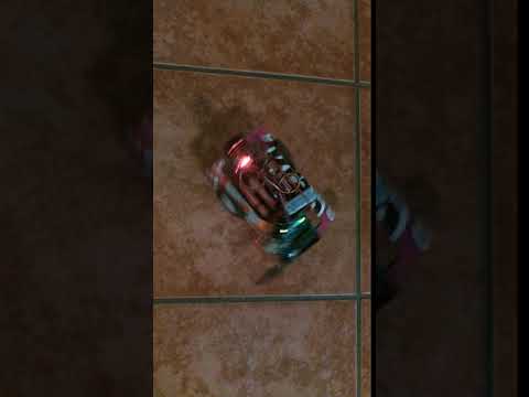
Note: Ultrasonic Sensor Is Not Set Up Yet... Will Do So in Part II.
Thank You!
I have been a member of instructables for many years, but this is my first instructable. I want to thank all those who have posted instructables before as I have used many. They are way harder to create than I thought!