ChafeSense - the Anti-Chafe Shirt
by feliciahmm in Circuits > Arduino
60 Views, 0 Favorites, 0 Comments
ChafeSense - the Anti-Chafe Shirt

Yunseo Chang, Tugce Naz Demir, Felicia Hamm
Have you ever run so fast, so long so breathtakingly …
That potentially your nipples started to hurt?
But what should you do? Grit your teeths, tape your nipples or worse: Quit???
First of all: You are not alone!
- A massive 92% of marathon runners experience chafing
- (research conducted by Vaseline)
- with 67% saying that it leads to bleeding (runners world- Rachel Boswell Apr.2026)
Reasons
- Repeated friction → contact + accelerated movement
- Sweat → humidity + salt
- Heat
So with this in mind we tried to fight this problem and Save the Nipples!
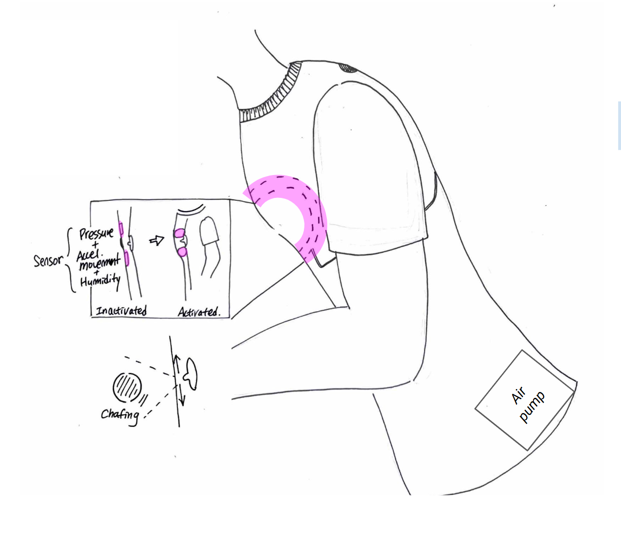
We tried to solve the problem with the inflating wearables.
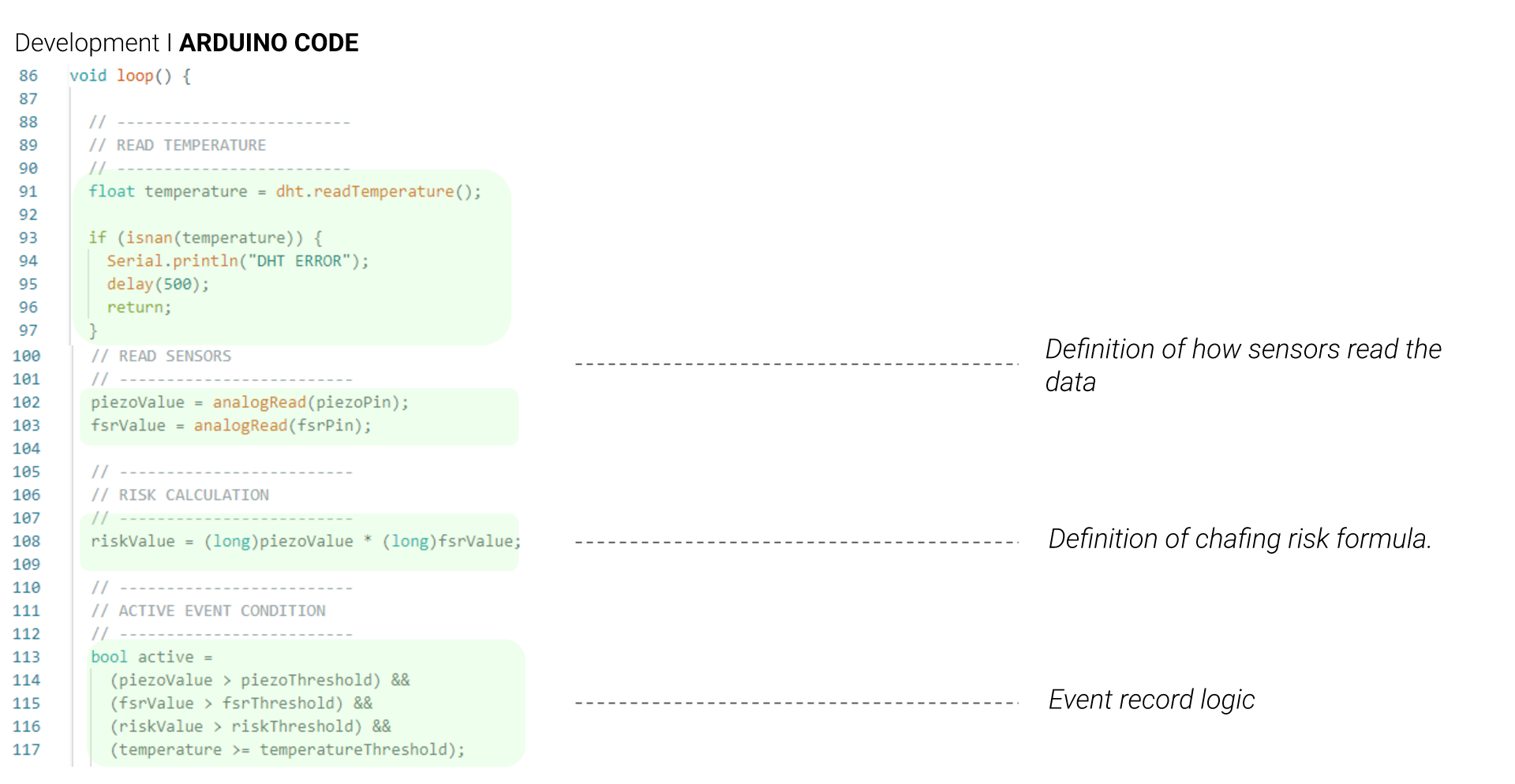
Since we wanted to get the friction value with the off the shelf sensors, we tried by combining three sensor inputs—pressure, movement, and moisture—to estimate chafing risk as a composite condition rather than a single factor.
When all three exceed a defined threshold simultaneously, the system interprets this as a high-risk state and turn the light on to alert, “You’re in Danger”.
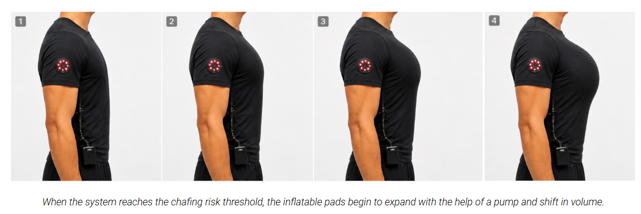
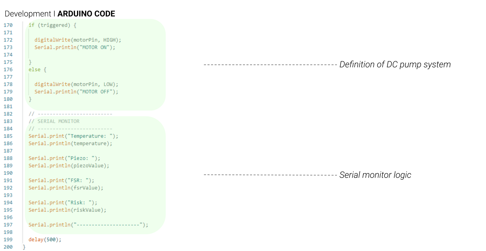
In response, the LED alerts the user that the air pump will activate to inflate a inflatable structure around the nipple, reducing friction and protecting the skin in real time.
Supplies
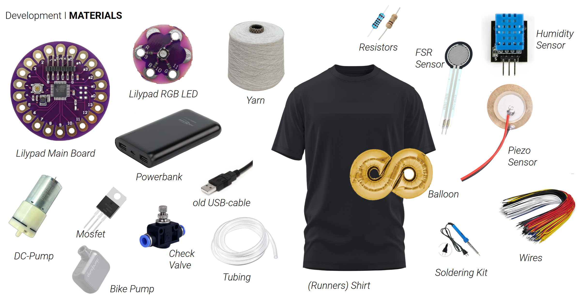
Sensors:
- FSR sensor (touch)
- piezo sensor (vibration)
- DHT11 (temperature and humidity)
- resistors (1k and 1M Ohm)
Control and circuit:
- Lilypad Main Board
- RGB LED (to check the sensors)
- wires
- soldering Kit
- Powerbank
- old USB-cable
Inflatables:
- balloon (donut or 8-shaped)
- tubing
- DC-pump
- energy supply for the pump
- Check Valve
- Mosfet
- resistor (1k)
Shirt
- old shirt
- yarn
- tape
Overview
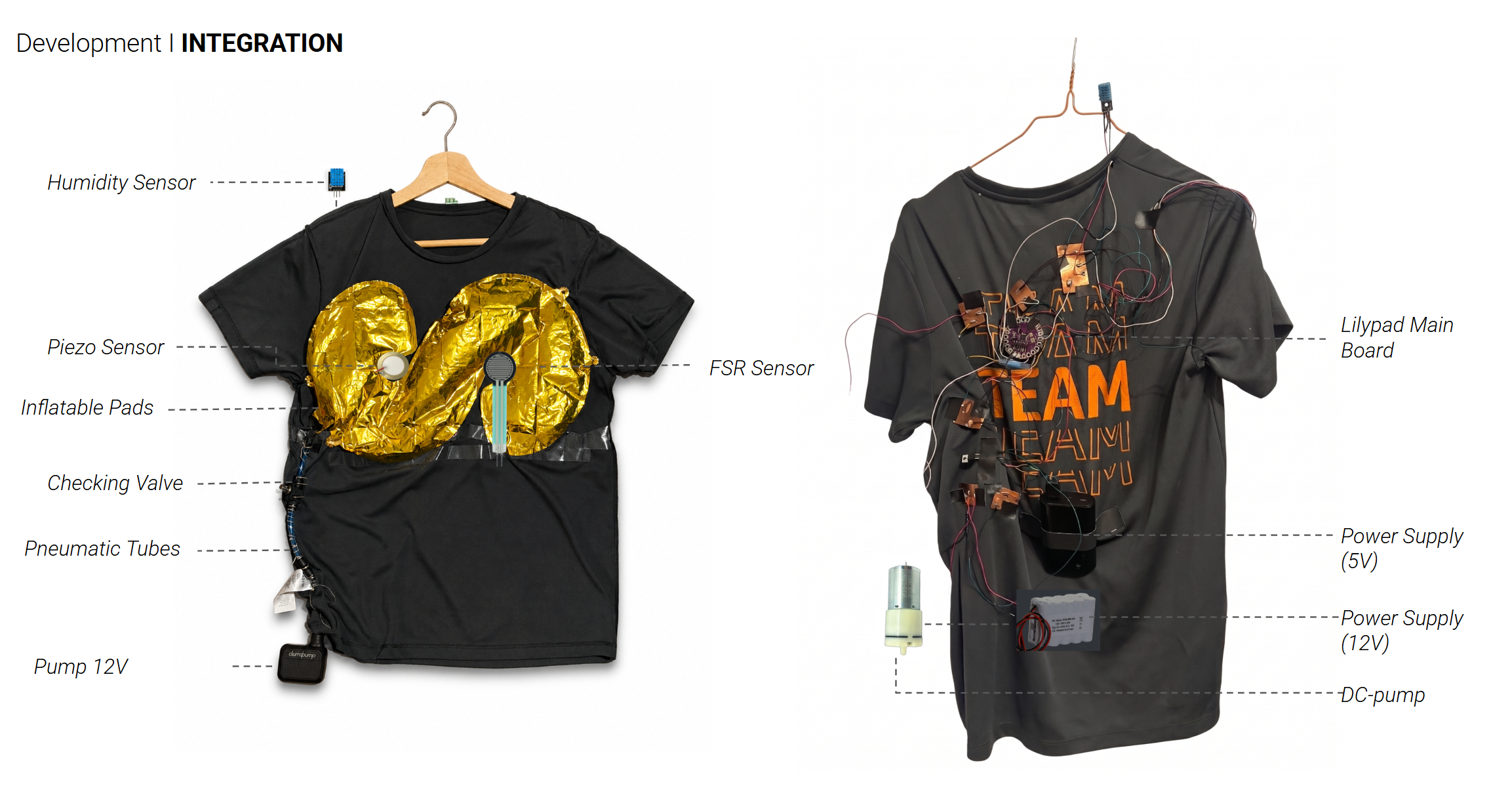
In the first picture, we can see an overview of both systems integrated into the shirt, the pneumatic system and the electronic components. The pneumatic elements are sewn into the inner layer of the t-shirt, the sensors are positioned around the nipple line to capture pressure and movement effectively.
The microcontroller and power supply are placed on the back. This placement helps distribute the weight more comfortably, keeps the front area flexible and unobstructed, and reduces interference with the sensors, making the system more stable and wearable.
Pneumatic System
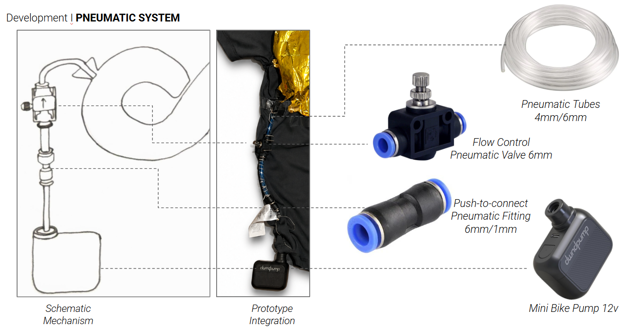
For the pneumatic system, we followed the seam lines of the t-shirt, using the thickness of the seams as a natural pathway for integrating the components.
To control the airflow going into the balloon, we used a passive pneumatic control valve. This allowed us to guide the air in a single direction and ensure a smoother, more controlled flow.
We also used push-to-connect pneumatic fittings to connect a tube that matches the outlet size of the DC-pump. Since the pump delivers air at a relatively low rate, it is necessary to connect the DC-pump to an external power supply with 12V.
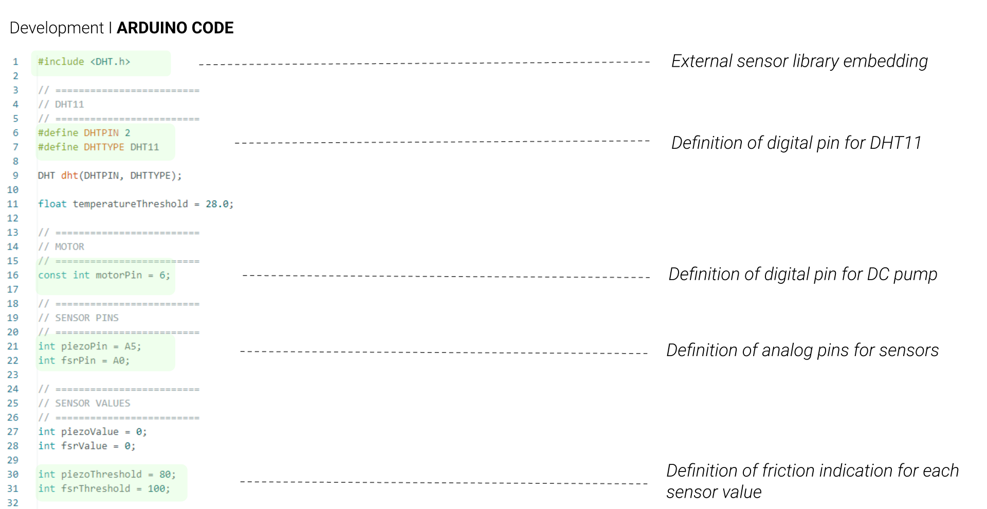
To control the DC-pump you need to connect the pump to the Mosfet and the digital pin 6 of the Lillipad main board as shown in the circuit diagram.
Sensor System
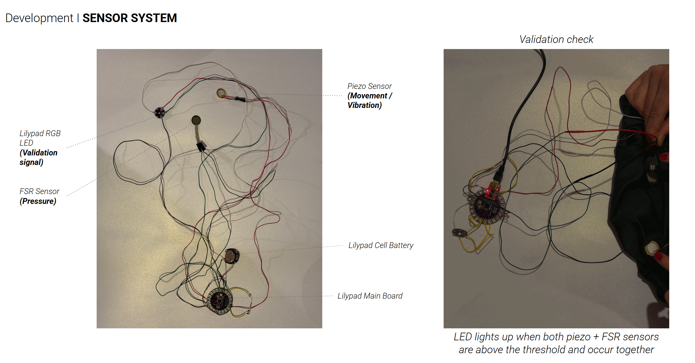
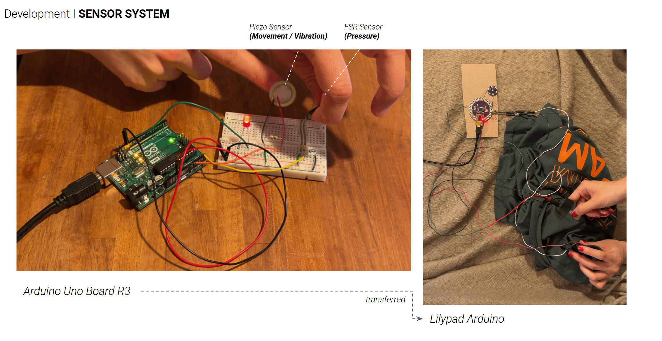
[Check circuit before sewing it in:]
1.
We firstly tried with the arduino uno board R3 to test whether the sensors are working correctly and transfer the circuit into the The LilyPad Arduino (which is designed for e-textiles and wearables projects) We tried to connect with the conductive yarns and tapes, however, we detected noises and imprecise values, we went with the alternatives by soldering the jumper wires (picture 3).
2.
For our validation check, we tried with piezo and FSR sensors to get the movement and pressure and RGB LED, which you can see in picture 2.
Circuit
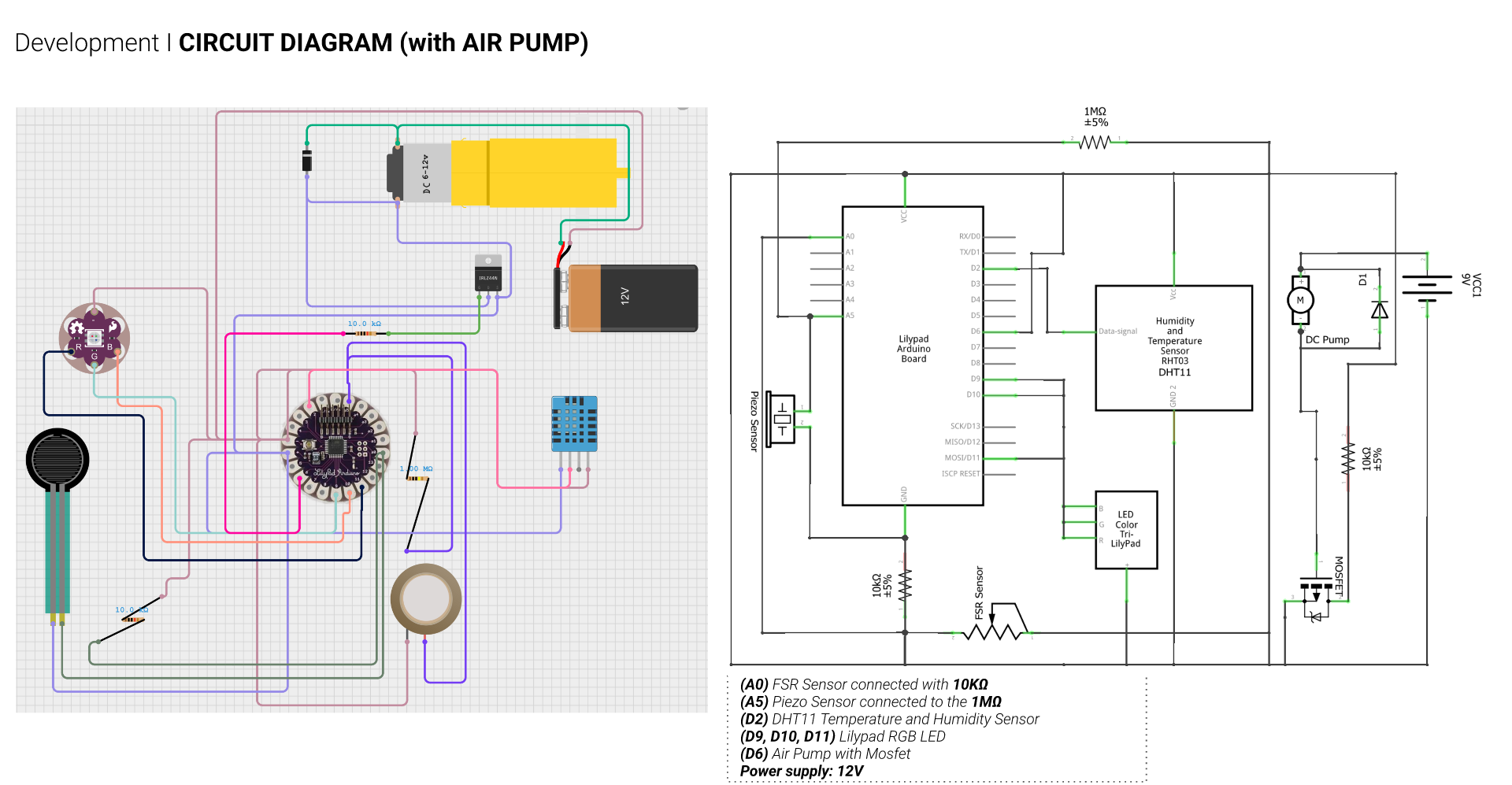
Here you can see the circuit diagram with an air pump controlled through using a MOSFET as a switch to safely control the 12V air pump with the low-voltage signal from the LilyPad and multiple sensors as well as an LED.
The MOSFET allows us to separate the high-power circuit from the microcontroller while still controlling it, so MOSFET turns pump ON/OFF and within the code, we’re thinking to modulate the air flow.
The gate resistor helps stabilize the signal, while the diode protects the circuit from voltage spikes produced when the motor turns off. In this way, the sensor logic from the LilyPad can safely trigger inflation.
The sensors are seperately connected to the Lillipad:
The FSR-sensor is conncted from VCC to A0 and parallely over a 10 000 Ohm (10k Ohm) resistor to ground. This is a voltage divider. The voltage difference between the A0 pin and GND is measured and results in touch signals.
The piezo-sensor which detects the vibration, is connected to A5 to ground (GND). From A5 to ground there is a parrallel connection via a 1 mega-ohm (1M Ohm) resistor. (That is called a pull-down-resistor to clear the A5 pin from remaining voltage after a piezo signal.)
The humidity sensor is connected to + (left pin) GND (right pin) and the digital pin 2 (middle pin). This version contains already an inbuilt resistor.
An RGB-Lillipad-LED is connected to the digital pins 9, 10 and 11 to test if the sensors are working.
Code



Downloads
Final Video

This is our final video to see the full potential of ChafeSense- our anti chafe shirt!