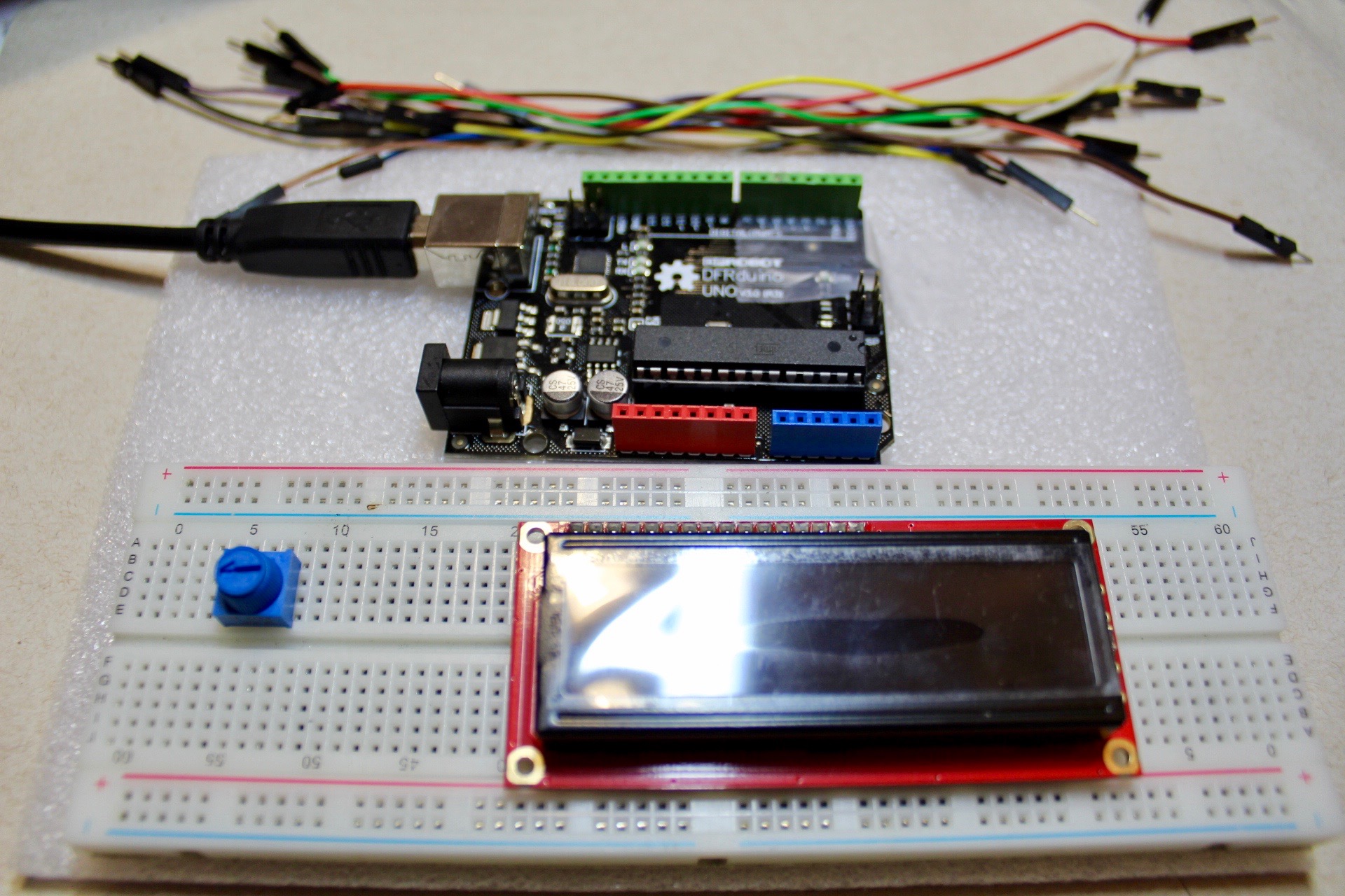
Cheap Digital Thermostat Display
by JeanC117 in Circuits > Arduino
1089 Views, 13 Favorites, 0 Comments
Cheap Digital Thermostat Display


This is a cheap but effective temperature monitor which displays the current temperature indoors onto a screen. It uses a TMP36 chip which read the temperature and a 16x2 LCD to display it. Overall it only costs about $18, depending on where you supply these items.
For this project, my goal is to monitor the temperature of my room, so I know when to properly ventilate it, especially with a few computers running full-time in the background, along with the stinking hot summer weather. I normally, have a high heat tolerance and don't notice the gradual changes even if it's around 28 degrees, so this device gives me an objective perspective.
In the future, I plan on mounting the IC outdoors, so I can monitor the weather and figure out what appropriate clothing to wear, especially helpful in hot summer days and cold winter days!
Bill of Materials (BoM)

- Arduino Uno - $7
- Temperature Sensor - TMP36 - $2
- 16x2 LCD Screen - $7
- Jumper Cables - $1
- Potentiometer - $1
LCD Screen Hookup


Distribute power in parallel using the breadboard's longest rails.
- Red Rail: Connect 3.3V pin of the Arduino to this rail.
- Black Rail: Connect any GND pin of the Arduino to this rail.
Connect the LCD to power
- Black, white, and brown wires: Connect pin 1, 5, and 16 of the LCD screen to the blue rail on the breadboard
- Yellow wires: connect pin 2 and 15 of the LCD screen to the red rail on the breadboard
Connect the LCD signals to the Arduino
- Purple, White (x2), Grey wires: Connect pins 14, 13, 12, and 11 on the LCD to pins 2, 3, 4, and 5 on the Arduino, respectively.
- Blue and Green wires: Connect pins 4 and 6 on the LCD to pins 11 and 12 on the Arduino.
Wiring the Temperature Sensor


Be careful about the polarity of the temperature sensor when plugging it in, because reversing it will cause ti to overheat and may burn you.
I find it easiest to hold it with the flat edge facing my right, then I know the order is ground, signal, then VCC, all in order from top to bottom.
- Green wire: This is the ground pin, connect it to GND on the Arduino.
- Orange middle wire: This is the signal pin, connect it to pin A0 on the Arduino
- Orange outer wire: This is the VCC pin, connect it to 3.3V on the Arduino.
Potentiometer hookup (from picture)
- Brown wire: Connect pin 3 on the LCD to the potentiometer's middle signal pin. Then connect the outer pins of this potentiometer to the power rail, in any order, there is no polarity requirements.
Coding

// Load the LiquidCrystal library
#include  <LiquidCrystal.h>
<liquidcrystal.h>// Initialize the library with the pins we're using.
LiquidCrystal lcd(12,11,5,4,3,2);
//temperature analog input pin constant </liquidcrystal.h>
const int tempPin = 0;
//raw reading variable
int tempVal;
//voltage variable
float volts;
//final temperature variables
float tempC;
void setup()
{
  // begin lcd of this particular size
  lcd.begin(16, 2);
  // Data sent to the display will stay there until it's
  // overwritten or power is removed.
  lcd.clear();
  // Now we'll display a message on the LCD!
  lcd.print("Current Temp:  ");
}
void loop()
{
//read the temp sensor and store it in tempVal
tempVal = analogRead(tempPin);
//converting that reading to voltage by multiplying the reading by 3.3V (voltage of //the 101 board)
volts = tempVal * 5.0;
volts /= 1023.0;
tempC = (volts - 0.5) * 100 ;
lcd.setCursor(0,1);
lcd.print(tempC);
//wait a bit before taking another reading
delay(1000);
}