Circuit With One LED & Potentiometer
by tejbho305 in Circuits > Arduino
288 Views, 1 Favorites, 0 Comments
Circuit With One LED & Potentiometer

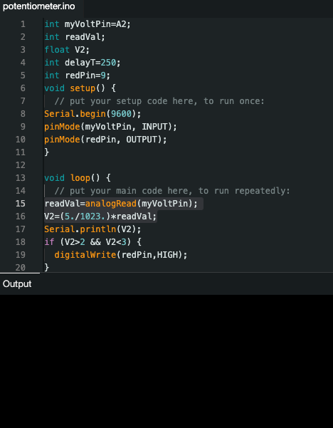
The LED will turn on when the potentiometer is between 2 values. It will turn off otherwise. The Serial monitor in the Arduino IDE app will continuously print the value of the potentiometer.
Supplies
The circuit uses:
- 1 LED
- 1 potentiometer
- 1 330 ohm resistor
- Elegoo UNO R3 microcontroller board
- Breadboard
- Laptop
- USB cord
Install Arduino IDE

Go to https://www.arduino.cc/en/software
Connect the Microcontroller Board to Laptop

Use a USB cord to attach the Elegoo board to your device.
Attach the LED

Connect one wire from pin 9 to the resistor, then connect the resistor to the LED. Then use another wire to connect the LED to ground.
Attach the Potentiometer

Put the potentiometer on the breadboard. The left wire goes to power (5V). The right wire goes to ground.
Add the Knob to the Potentiometer

Use another wire to connect the bottom of the potentiometer to A2. Finally, add the the knob to the potentiometer.
Write the Program

https://github.com/tejbho/ArduinoProjects/blob/main/potentiometer/potentiometer.ino
Downloads
Test the Circuit


Turn the knob on the potentiometer until the LED light turns on. The light should turn on when the value is between 2 and 3. Then turn the knob back to see that it turns off.