ColourScope: a True Portable RGB Color Prototyping Lab
by SUCHI2004 in Circuits > Arduino
108 Views, 1 Favorites, 0 Comments
ColourScope: a True Portable RGB Color Prototyping Lab
.jpeg)
Color is everywhere—from breathtaking sunsets and vibrant rainbows to the screens we use every day. But have you ever wondered how your phone, TV, or computer monitor can create millions of colors using only Red, Green, and Blue (RGB) light?
The answer lies in additive color mixing. Unlike paints, where mixing colors usually creates darker shades, light behaves differently. By adjusting the intensity of Red, Green, and Blue light, we can produce almost every color visible to the human eye. This simple yet fascinating principle powers modern displays, projectors, LED lighting, and many of the technologies we use every day.
Although RGB color theory and the visible light spectrum are taught in schools, they're usually explained through diagrams rather than real-world demonstrations. At the same time, artists, designers, and makers often experiment with colors before starting a project, but most digital color pickers only display colors on a screen instead of letting you experience them as real light.
That's what inspired me to create ColourScope.
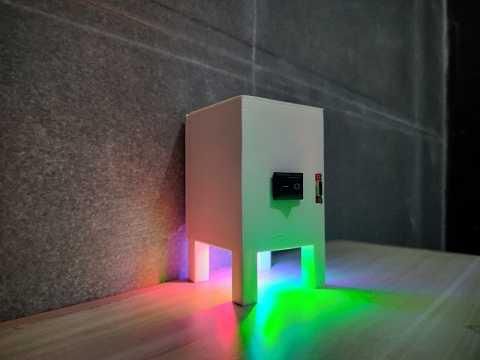
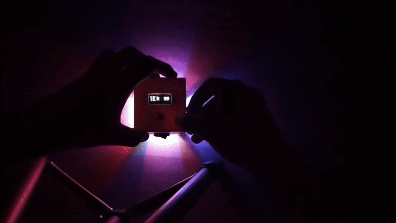
ColourScope is a portable RGB Color Prototyping Lab that combines science and creativity into one compact device. It lets you physically mix Red, Green, and Blue light, project the resulting color onto a wall or canvas, and instantly see how each adjustment changes the final color. Whether you're an artist exploring new color combinations, a student learning the science of light, or a teacher demonstrating additive color mixing, ColourScope transforms color theory into an interactive, hands-on experience.
Let's build ColourScope and discover how just three colors of light can create an entire world of color! 🌈
Supplies

.jpeg)
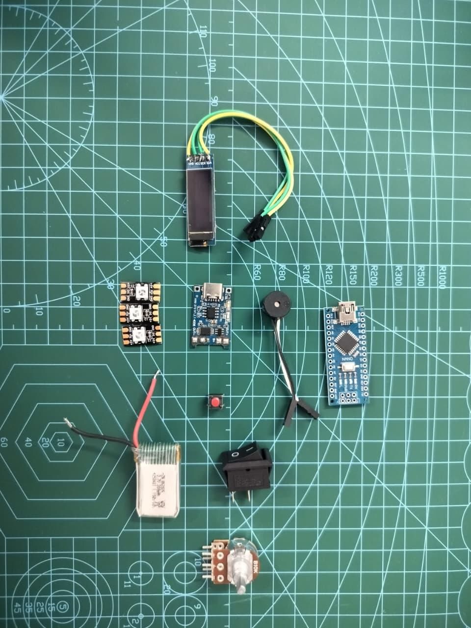
Electronics
- 1 × Arduino Nano
- 1 × 0.96" I2C OLED Display (SSD1306)
- 3 × WS2812B NeoPixel LEDs
- 1 × 10kΩ Potentiometer
- 1 × Tactile Push Button
- 1 × Active Buzzer
- 1 × TP4056 Li-ion Charging Module
- 1 × Slide ON/OFF Switch
- Jumper Wires / Hook-up Wire
Power
- 1 × 3.7V Li-ion Battery (18650 or similar)
3D Printed Parts
- 1 × Main Enclosure
- 1 × Top Lid
- 1 × Bottom Cover
(STL files are attached in this Instructable.)
Tools Required
- Soldering Iron
- Solder Wire
- Hot Glue Gun (Optional)
- Wire Stripper
- Side Cutter
- Tweezers (Optional)
- USB Cable for Arduino Nano
- Computer with Arduino IDE
Software
- Arduino IDE
- Adafruit NeoPixel Library
- Adafruit SSD1306 Library
- Adafruit GFX Library
Understanding How Colors Combine
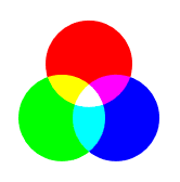
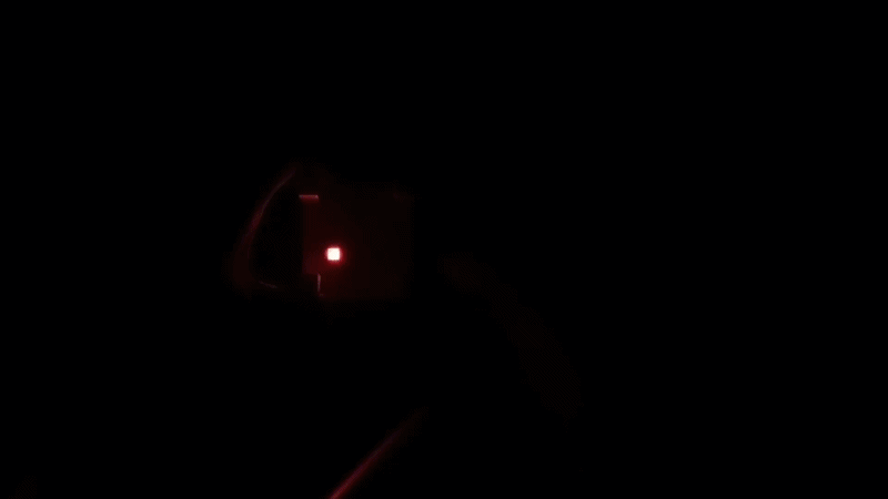
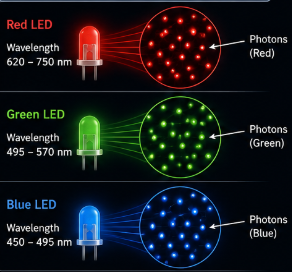
Before we start building ColourScope, let's understand the science behind it.
Unlike paints or inks, which use subtractive color mixing, light follows the principle of additive color mixing. In additive mixing, different colored lights are combined to create new colors. As more light is added, the resulting color becomes brighter. This is why combining all three primary colors of light produces white, while the absence of light appears black.
The three primary colors of light are:
- 🔴 Red
- 🟢 Green
- 🔵 Blue
When these colors overlap, they create secondary colors:
- 🔴 Red + 🟢 Green = 🟡 Yellow
- 🟢 Green + 🔵 Blue = 🔵 Cyan
- 🔴 Red + 🔵 Blue = 🟣 Magenta
- 🔴 Red + 🟢 Green + 🔵 Blue = ⚪ White
Our eyes perceive color using specialized cells called cone cells, which are sensitive to red, green, and blue wavelengths of light. The brain combines the information from these cone cells to recognize millions of different colors. By simply changing the brightness of each RGB light source, we can recreate almost any color visible to the human eye.
This same principle is used in televisions, computer monitors, smartphones, projectors, LED displays, stage lighting, and digital cameras, where every color on the screen is created by adjusting the intensity of red, green, and blue light.
ColourScope demonstrates this process in real time. As you adjust the Red, Green, and Blue values, you can instantly observe how different colors are produced, making it an interactive way to learn the fundamentals of light and color.
The diagram below illustrates how additive RGB color mixing works.
3D Print the Enclosure
.gif)
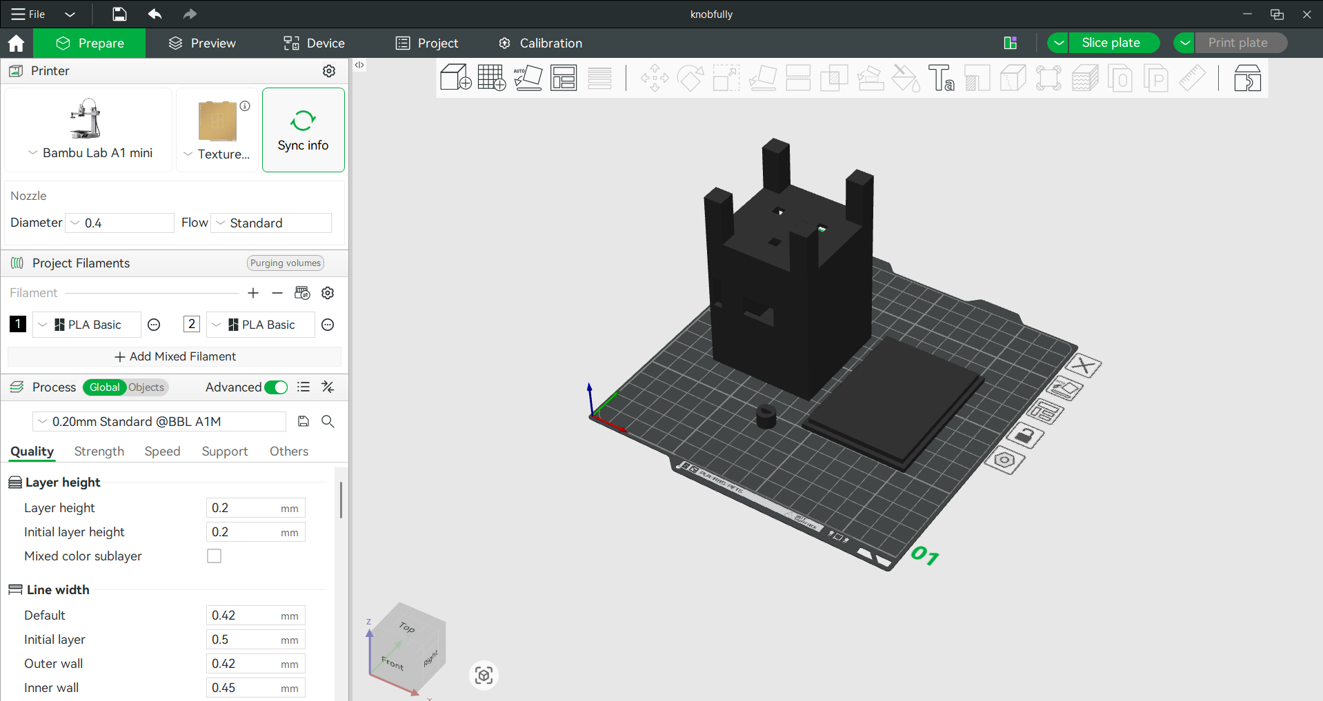
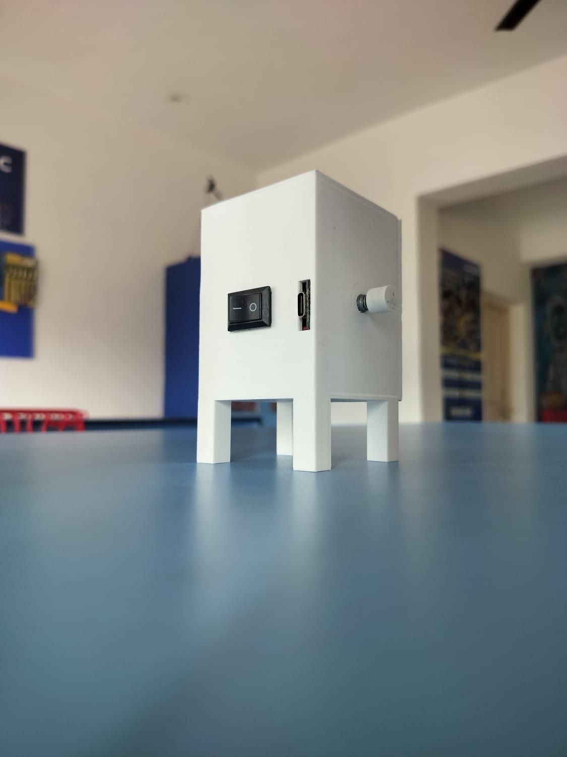
Now it's time to print the enclosure that houses all the electronics. I designed a compact case that keeps every component securely in place while allowing the RGB light to project freely. The enclosure is made of three parts: the main body, the top cover, and the bottom cover.
I printed all the parts using white PLA filament. White not only gives the device a clean, professional look but also reflects light better, helping the projected colors appear brighter and more vibrant.
Recommended Print Settings
- Material: PLA
- Layer Height: 0.2 mm
- Infill: 15–20%
- Wall Count: 3
- Supports: Only where required
- Print Speed: 50–60 mm/s
- Nozzle Temperature: 200–210°C (depending on your filament)
- Bed Temperature: 60°C
Once the prints are complete, remove any supports and lightly sand the edges if needed for a cleaner finish. Before assembling everything, test-fit the Arduino Nano, OLED display, switch, potentiometer, push button, battery, and NeoPixel LEDs to ensure all cutouts align correctly.
The enclosure is now ready for the electronics assembly in the next step.
Upload the Code to the Arduino Nano
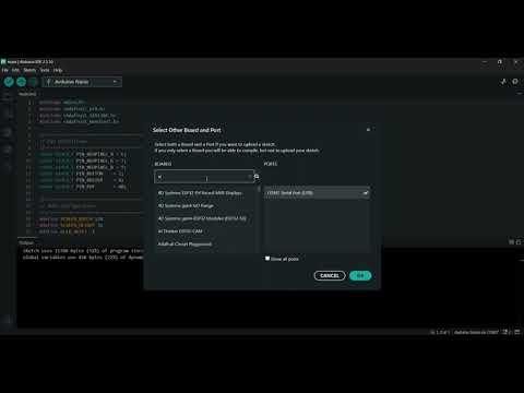
Now it's time to bring ColourScope to life by uploading the firmware to the Arduino Nano.
If you're new to Arduino, don't worry—this process only takes a few minutes.
What You'll Need
- Arduino Nano
- USB Mini-B Cable
- Arduino IDE installed on your computer
- ColourScope source code (attached below)
Install the Required Libraries
Before uploading the code, install the following libraries from the Arduino Library Manager.
- Open Arduino IDE.
- Go to Sketch → Include Library → Manage Libraries...
- Search for and install these libraries:
- Adafruit NeoPixel by Adafruit
- Adafruit SSD1306 by Adafruit
- Adafruit GFX Library by Adafruit
Once all three libraries are installed, you're ready to upload the code.
Upload the Code
- Connect the Arduino Nano to your computer using a USB Mini-B cable.
- Open the ColourScope sketch provided with this project.
- Go to Tools → Board and select Arduino Nano.
- Under Tools → Processor, select the correct processor for your board:
- ATmega328P (Old Bootloader) (Most Nano clone boards)
- ATmega328P (Official Arduino Nano)
- Select the correct COM Port from Tools → Port.
- Click the Upload (→) button and wait for the upload to finish.
If everything is configured correctly, the Arduino IDE will display:
Done Uploading!
Your Arduino Nano is now programmed and ready for the next step.
Tip: If you receive an stk500_recv(), programmer is not responding, or another upload error, try selecting ATmega328P (Old Bootloader) from the Processor menu, as many Arduino Nano clone boards use the older bootloader. Also, ensure the correct COM port is selected and the USB cable supports data transfer (not just charging).
Downloads
Prepare the Electronics
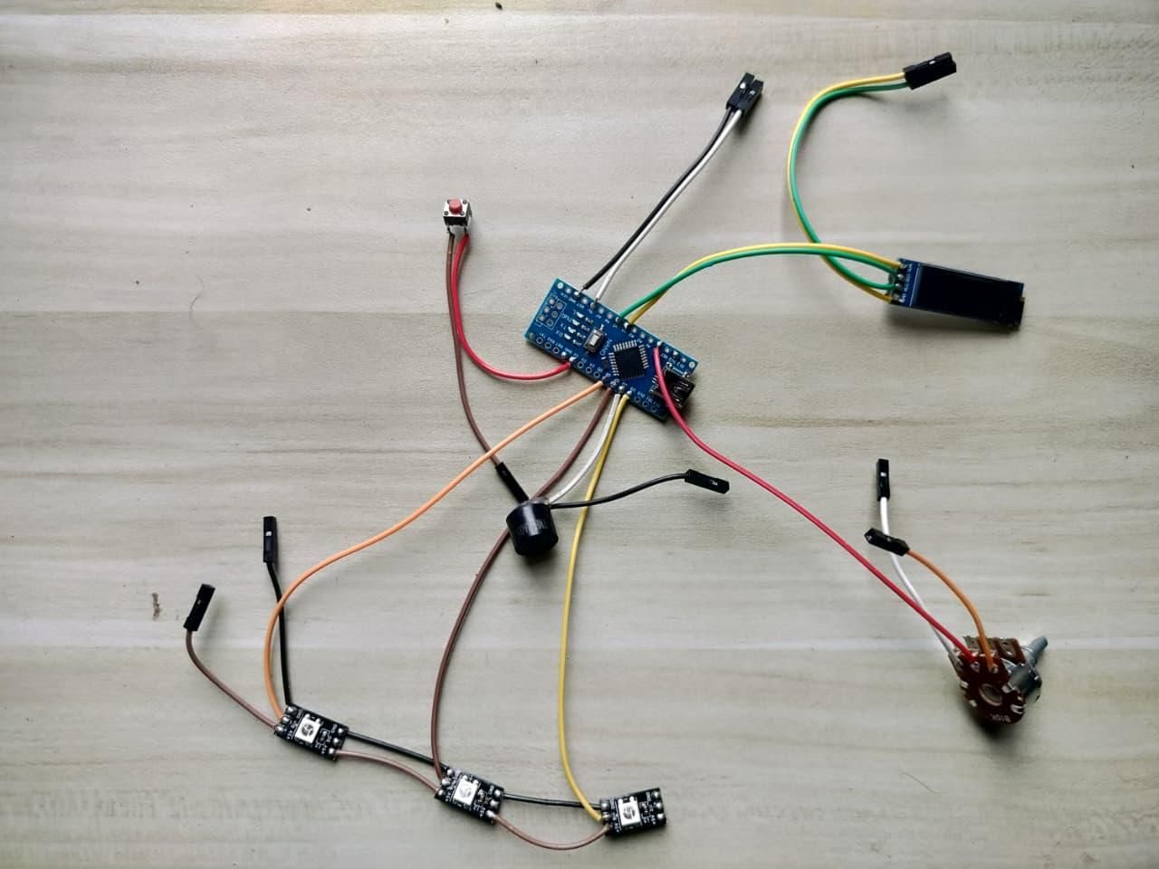
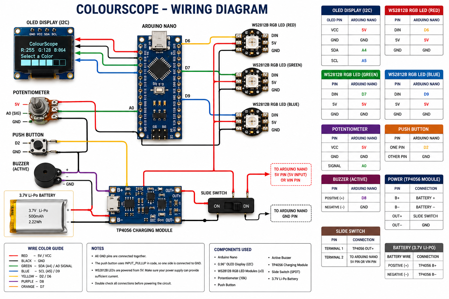
With all the parts printed, it's time to prepare the electronics. Solder the wires to each component and connect everything according to the wiring diagram below. Double-check every connection before powering on the circuit.
OLED Display (I2C)
- VCC → 5V
- GND → GND
- SDA → A4
- SCL → A5
Red NeoPixel LED
- DIN → D6
- VCC → 5V
- GND → GND
Green NeoPixel LED
- DIN → D7
- VCC → 5V
- GND → GND
Blue NeoPixel LED
- DIN → D9
- VCC → 5V
- GND → GND
Potentiometer
- VCC → 5V
- GND → GND
- Signal → A0
Push Button
- One Terminal → D2
- Other Terminal → GND
Active Buzzer
- Positive (+) → D8
- Negative (−) → GND
TP4056 Charging Module
- B+ → Battery Positive (+)
- B− → Battery Negative (−)
- OUT+ → Slide Switch
- OUT− → Arduino Nano GND
Slide Switch
- Terminal 1 → TP4056 OUT+
- Terminal 2 → Arduino Nano 5V (or VIN if using a higher input voltage)
3.7V Li-ion Battery
- Positive (+) → TP4056 B+
- Negative (−) → TP4056 B−
Tip: Use different wire colors for 5V, GND, and signal wires to make troubleshooting easier. Before moving on to the next step, compare your circuit with the wiring diagram and ensure all solder joints are secure. This will save time during the final assembly.
Assemble the Enclosure
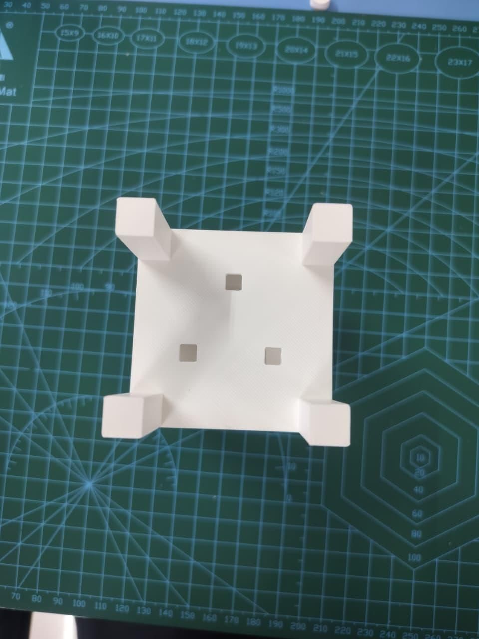
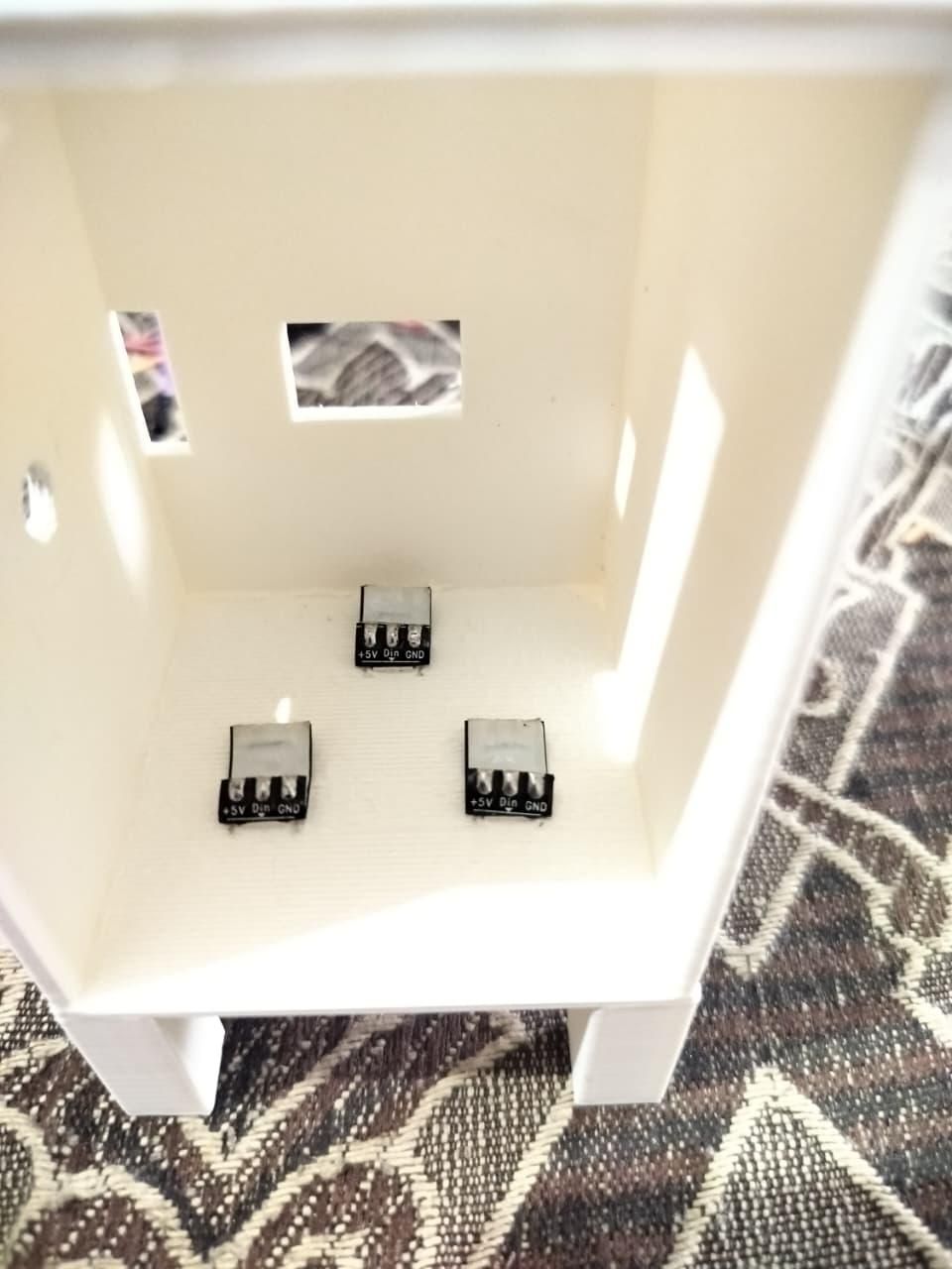
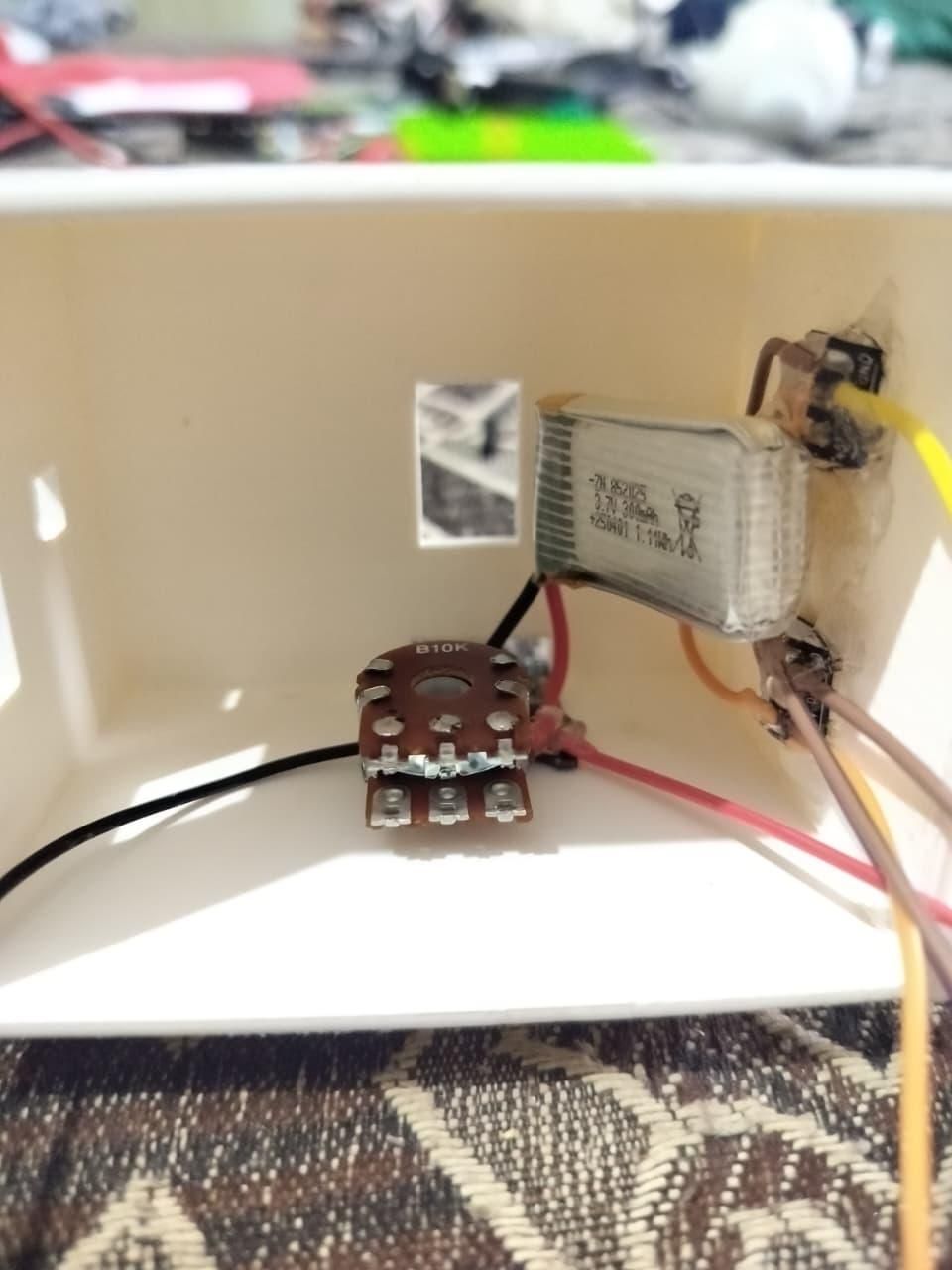
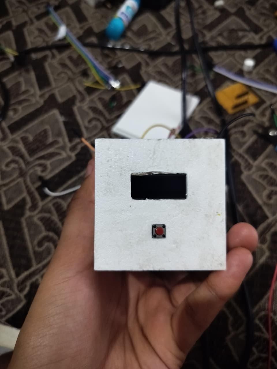
.jpeg)
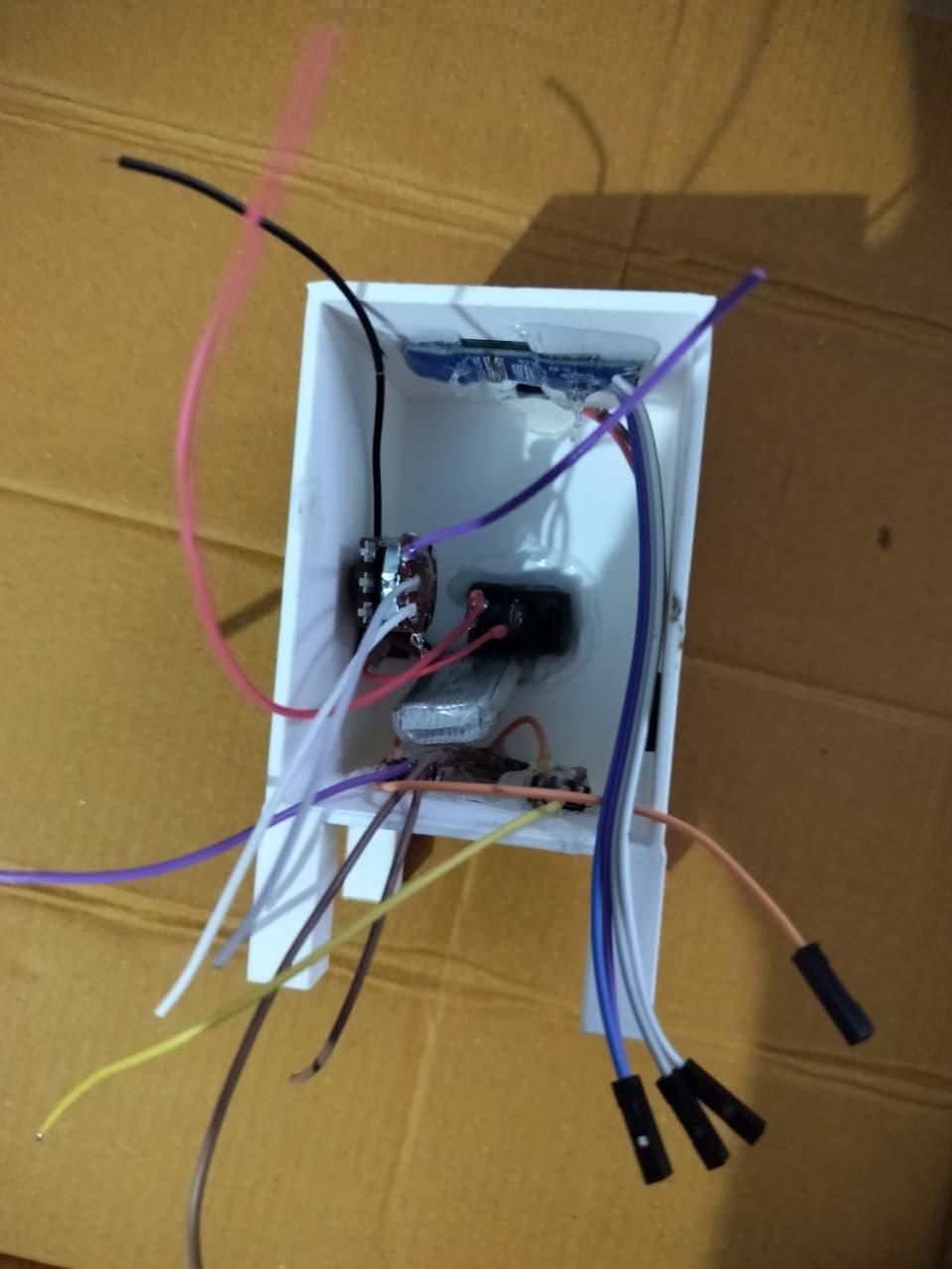
Now that all the electronics have been wired and tested, it's time to assemble ColourScope inside the 3D-printed enclosure.
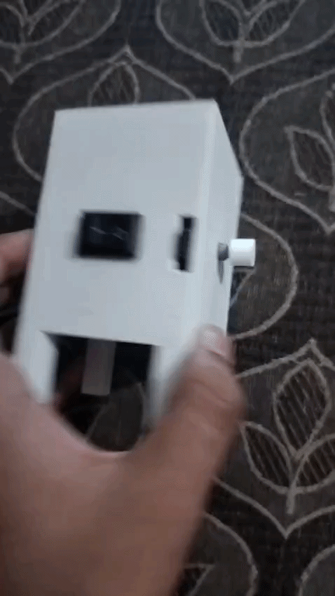
Begin by mounting the OLED display, potentiometer, push button, and slide switch into their respective cutouts on the front panel. Next, place the Arduino Nano, TP4056 charging module, and buzzer into their designated positions inside the enclosure. Finally, install the three NeoPixel LEDs and 3.7V Li-ion battery in their dedicated slots.
Carefully arrange the wiring to keep the interior neat and prevent any wires from being pinched or pulled during assembly. If needed, use a small amount of hot glue or double-sided tape to secure the components and keep them from moving.
As shown in the figure below, all the components should fit neatly inside the enclosure with enough room for proper cable management.
Once everything is positioned correctly, carefully align the lid with the main body of the enclosure and gently press it into place until it fits securely. Ensure that no wires are trapped between the two halves and that the lid sits flush with the enclosure.
Tip: Before closing the enclosure completely, power on the device to verify that the OLED display, NeoPixel LEDs, push button, potentiometer, and buzzer are all functioning correctly. Once everything has been tested, close the lid securely and your ColourScope is ready for the final testing step. 🌈
Testing ColourScope
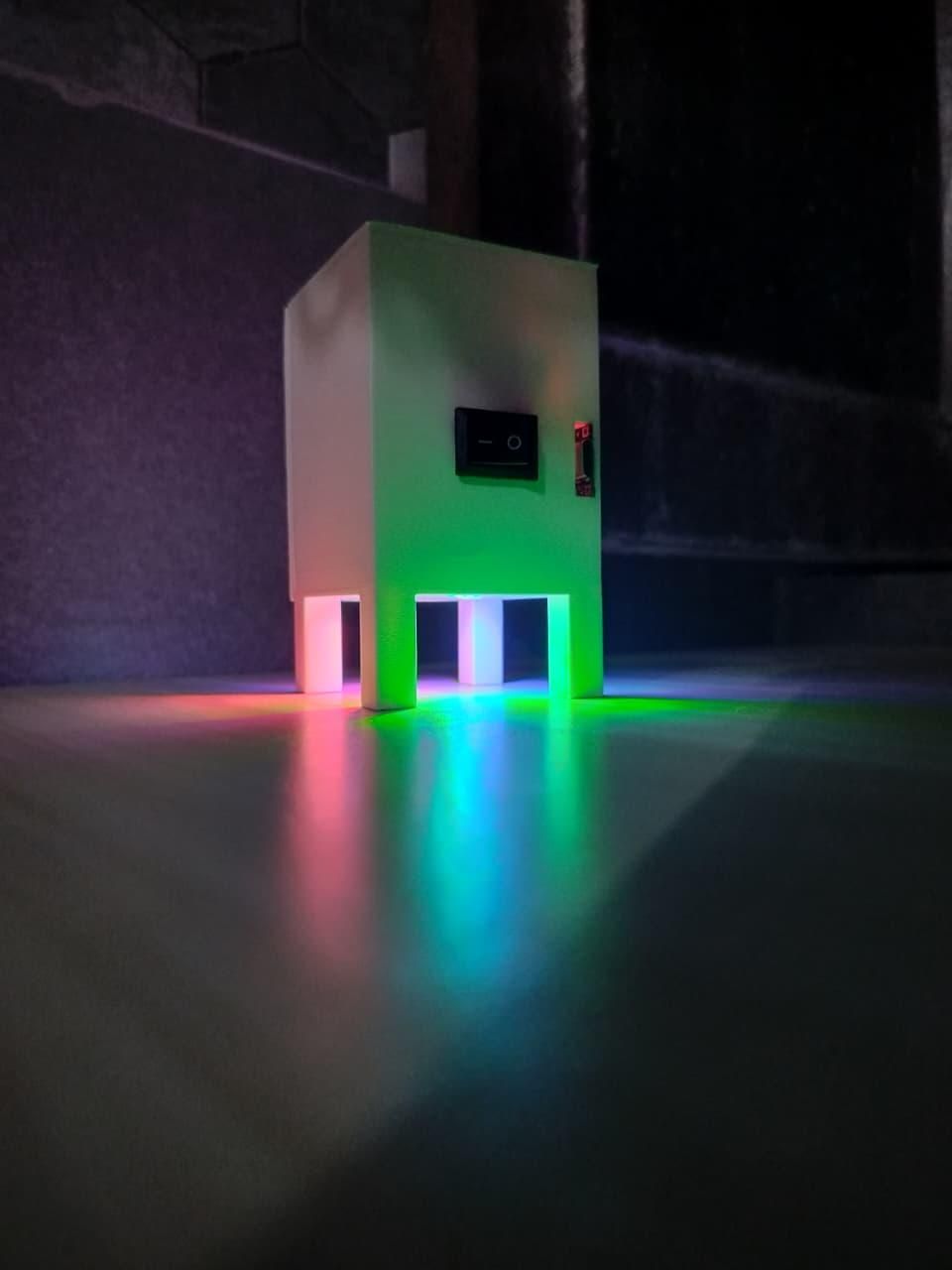
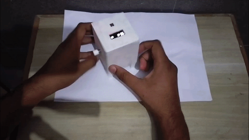
With the assembly complete, it's time to test your ColourScope.
Slide the ON/OFF switch to the ON position. The OLED display should light up, indicating that the device has powered on successfully. Use the push button to switch between the Red, Green, and Blue channels, then rotate the potentiometer to adjust the brightness of the selected color.
As you change the RGB values, watch the three NeoPixel LEDs combine to create different colors such as Yellow, Cyan, Magenta, White, and countless other shades.
Verify the following:
- ✅ ON/OFF switch powers the device correctly.
- ✅ OLED display starts and updates properly.
- ✅ Push button changes the selected RGB channel.
- ✅ Potentiometer adjusts the brightness of the selected color.
- ✅ NeoPixel LEDs respond smoothly to every adjustment.
- ✅ Buzzer provides feedback (if enabled).
- ✅ Battery powers the device reliably.
If all of these tests pass, your ColourScope is ready to demonstrate the fascinating science of additive RGB color mixing.
How to Use ColourScope
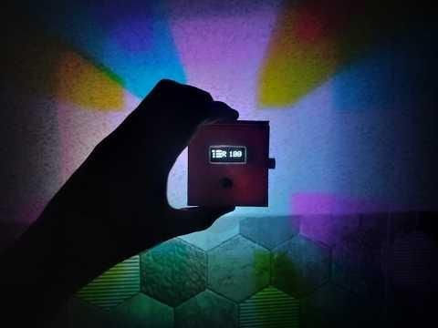
Now that your ColourScope is assembled, it's time to start exploring the fascinating world of RGB color mixing.
Slide the ON/OFF switch to the ON position to power the device. After a few seconds, the OLED display will turn on and show the currently selected color channel and its intensity.
Adjust the Light Intensity
Use the potentiometer to change the brightness of the currently selected color. Rotating the knob clockwise increases the intensity, while rotating it counter-clockwise decreases it.
Switch Between RGB Channels
Press the push button to cycle through the three color channels:
- 🔴 Red
- 🟢 Green
- 🔵 Blue
The OLED display indicates which channel is currently selected. After selecting a channel, use the potentiometer to adjust its brightness. By repeating this process for all three channels, you can create countless color combinations.
Experiment with Colors
Try creating some common colors by adjusting the RGB intensities:
- 🟡 Yellow (Red + Green)
- 🔵 Cyan (Green + Blue)
- 🟣 Magenta (Red + Blue)
- ⚪ White (Red + Green + Blue)
- ❤️ Different shades by varying the brightness of each color
This hands-on interaction makes it easy to understand how additive RGB color mixing works.
Charging the Battery
ColourScope includes a built-in TP4056 charging module, making it easy to recharge the battery.
Simply connect a USB cable to the charging module whenever the battery runs low. The charging indicator LEDs on the TP4056 will show the charging status, and once fully charged, the device is ready to use again.
Tip: Switch the device OFF while charging or when it is not in use to maximize battery life and ensure safe operation.
What We Learned & Conclusion
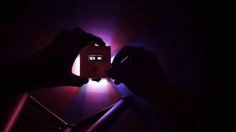
Building ColourScope is more than just assembling an electronic project—it's an opportunity to explore the fascinating science behind light and color. Throughout this project, we learned how additive RGB color mixing works and how combining different intensities of Red, Green, and Blue light can produce millions of unique colors.
We also gained hands-on experience with:
- RGB color theory and additive color mixing
- Arduino Nano programming
- Controlling NeoPixel LEDs
- Using PWM to adjust LED brightness
- Interfacing an OLED display
- Reading analog input with a potentiometer
- Using a push button for user interaction
- Battery-powered electronics with a TP4056 charging module
- Designing and assembling a 3D-printed enclosure
By building and experimenting with ColourScope, you can see in real time how the same RGB technology is used in televisions, smartphones, computer monitors, LED displays, projectors, and stage lighting. It transforms an abstract concept into something interactive, making it easier to understand and much more engaging to explore.
I hope this project has helped you better understand the science of light while inspiring you to create your own interactive educational gadgets. If you enjoyed this build, I'd really appreciate your vote in the Colors of the Rainbow Contest. Your support encourages me to continue designing and sharing open-source STEM projects for makers, students, and educators around the world.
Happy Making! 🌈