Computer Stand in Solidworks
by twphill3 in Design > Digital Graphics
236 Views, 0 Favorites, 0 Comments
Computer Stand in Solidworks

This project is made to give practice for TDE students in courses such as GC 120 and GC 350. It provides experience not only working on parts files but also working with an assembly of the parts that are made. This is a project that is meant to have functional use and is able to be 3D printed as four individual segments. Getting to use and interact with a project you create can help motivate students to want to further develop their technical skills in Solidworks.
By the end of this instructable, students will be able to:
Sketch and Extrude objects
Maintain accuracy of dimensions and constraints
Generate an assembly of the parts they created
STELs:
- Design in Technology and Engineering Education
- Integration of Knowledge, Technologies, and Practices
- Applying, Maintaining, and Assessing Technological Products and Systems
Supplies
Computer
- Any laptop or desktop computer capable of running Solidworks with multiple files open in a given instance.
Solidworks License
- This project is done entirely in Solidworks which is not a free to use application. A license is required to operate it whether it be through a school, business or personal purchase.
- Solidworks Licenses - https://www.solidworks.com/how-to-buy/solidworks-plans-pricing
Mouse (Highly Recommended)
- Solidworks can be extremely tedious to operate with a trackpad. Any mouse, wired or wireless, is recommended to make the process more seamless.
Create a Part File
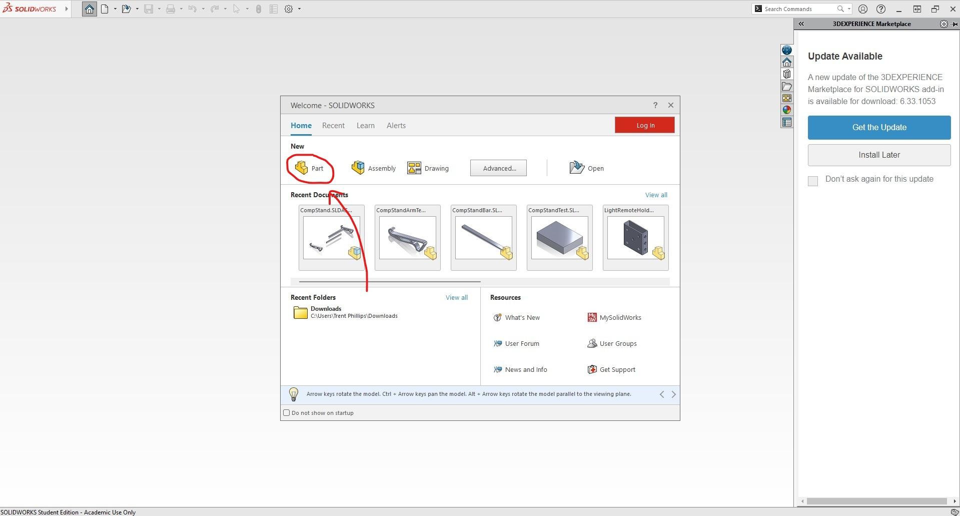
Start by launching Solidworks on your computer. A prompt should pop up asking if you want to make a part, assembly or drawing file. For now, just select Part to get started.
Once you are in the workspace you will need to confirm that you are operating under IPS (Inches, pounds, seconds). The tab in the bottom right of the page will allow you to set this as it will be important for recreating dimensions later on.
Sketch and Extrude Stand Bar
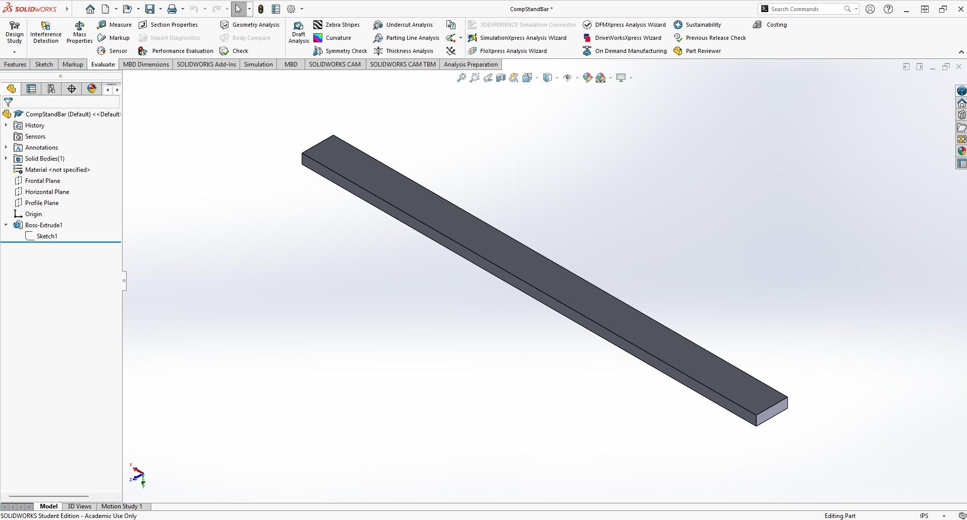

The first part that we will be making is the stand bar which will serve as a connector between the two arms. We will need two of these for our final assembly but fortunately we only need to create it one time.
Start by selecting the horizontal plane and then starting a new sketch on this plane. Once you have created a new sketch you will want to find the Rectangle Tool. Any variation of this tool will work as the dimensions we create will define this sketch. Sketch a rectangle.
Next, select the Smart Dimension Tool which is located next to the Sketch Tool. Use this tool to create the dimensions shown in the image above. 10.4in x 0.72in.
Navigate to the Features tab and select Extrude Boss/Base. The highlighted number on the side panel is your depth. Set this number to 0.22 inches and click the green check mark ✓.
Save this as a part file under a name that you will recognize later.
Sketch and Extrude Stand Arm
Create another part file and this time we will be sketching on the right plane.
Body Sketch
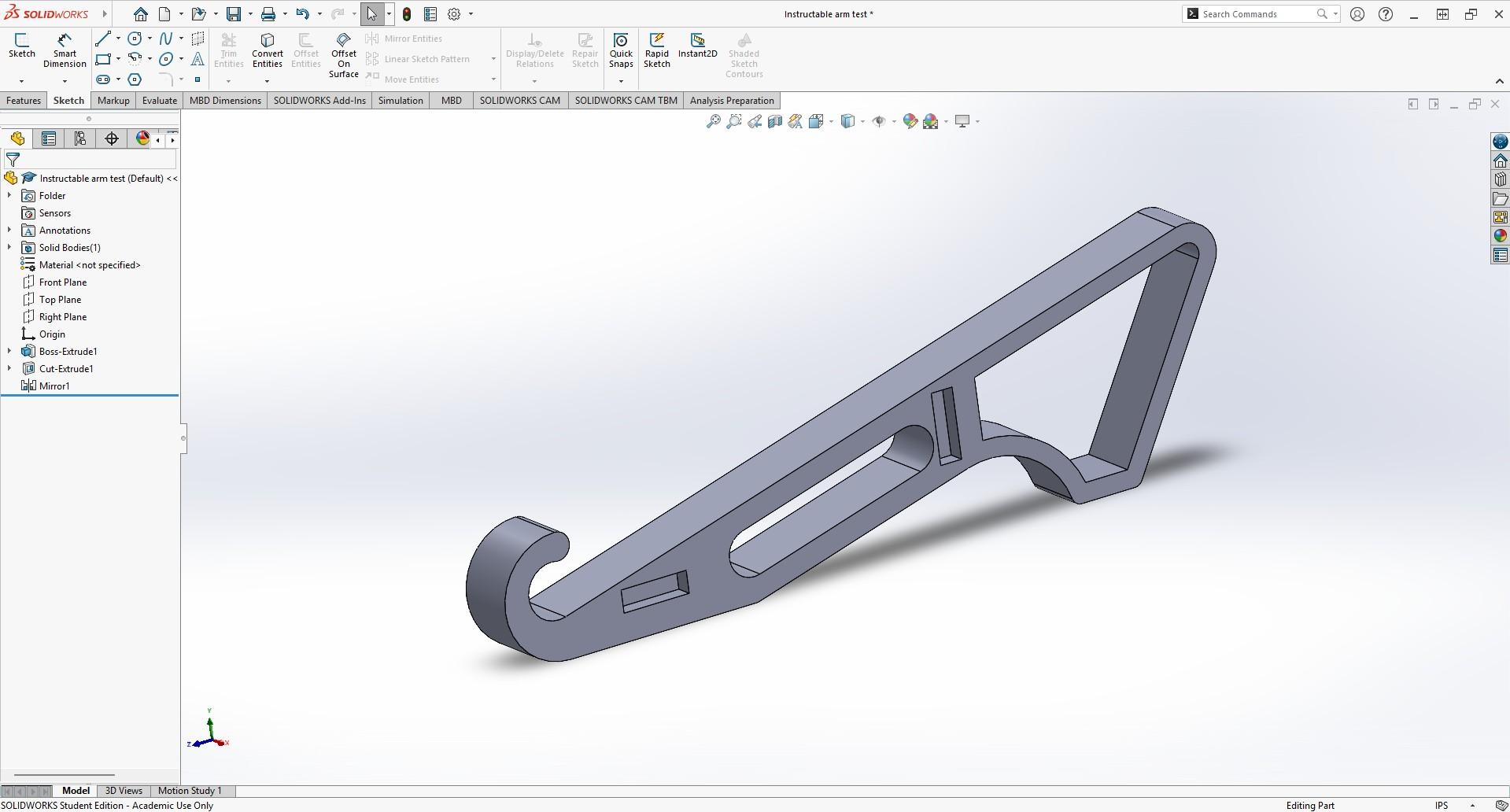
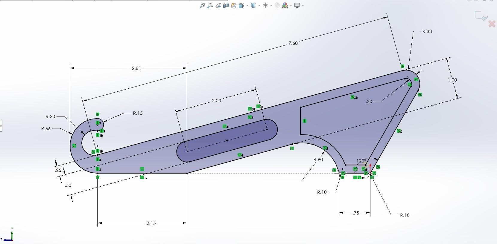
Begin sketching on the right plane using the Line tool. In order to get the curves from the reference image above, press the a key. The initial drawing will likely not look correct to the image but dimensions and relations will make it take shape.
Tips
- A large part of what defines this sketch are the green relations icons. If you have inconsistencies with the sketch make sure these line up.
- The dotted line at the bottom is a collinear relation between the two bottom lines. This is important to make sure that the part sits flush on the ground.
Straight Slot: The hole in the center of the arm is made using the Straight Slot tool found below the Line tool. Create a slot in the general area as shown and use the provided dimensions to define it.
Offset Entities: The hole found towards the back of the arm is created using the Offset Entities command found in the toolbar of the sketch tab.
- Before offsetting, create a vertical line to the right of the slot you created. This will assure that the entire component is not offset.
- Now select Offset Entities.
- Set the parameters to 0.2 inches and check the box for reverse.
- After selcting your desired lines (including the one you just drew), trim up any excess lines that were created in your offset.
- Click the green check mark ✓.
Sketch Fillet: Use the Sketch Fillet tool to create the curved edges at the bottom of the part. Choose a radius of 0.1 inches.
Extrude Boss/Base: 0.75 inches, midplane
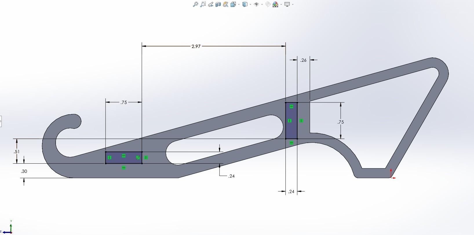
Socket Sketch
Open a new sketch and select the side of the part. This will allow you to create a new sketch onto it.
Using the Rectangle tool you will create two rectangles and dimension them as shown in the image provided above. These rectangles should not intersect with the holes created in the first sketch.
Extruded Cut: Look under the features tab and find the Extruded Cut feature. Set the Depth to 0.2 inches and make sure that the direction is set to blind. Click the green check mark ✓.
Mirror Sockets
Under the Features tab, find and select the drop down for Linear Pattern.
Select Mirror.
Choose the right plane as the object that you want to mirror. This should make a duplicate set of sockets on the other side of the part.
Click the green check mark ✓.
Save this as a part file under a name that you will recognize later.
Create Assembly File
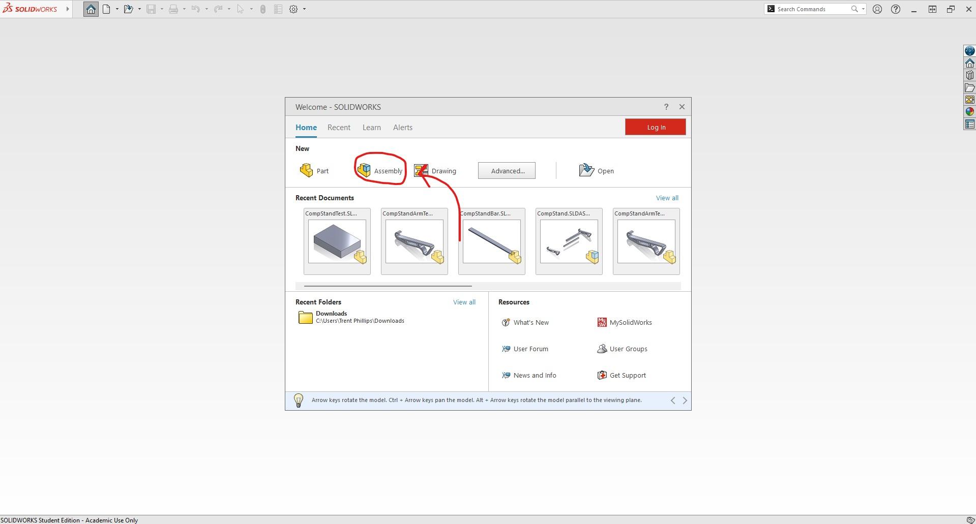
Return to the home page using the house icon on the top left of the page. This should bring you to the page you used to create a part file.
Instead of selecting Part, select Assembly.
Once the workspace opens your files should open displaying recently accessed files. Select the Stand Arm to place it into the assembly.
To add your other parts, navigate to the assembly tab and select Insert Components. This time when your files appear select the Stand Bar.
Repeat this once more for each part until you have two of each placed into your workspace.
Adding Mates
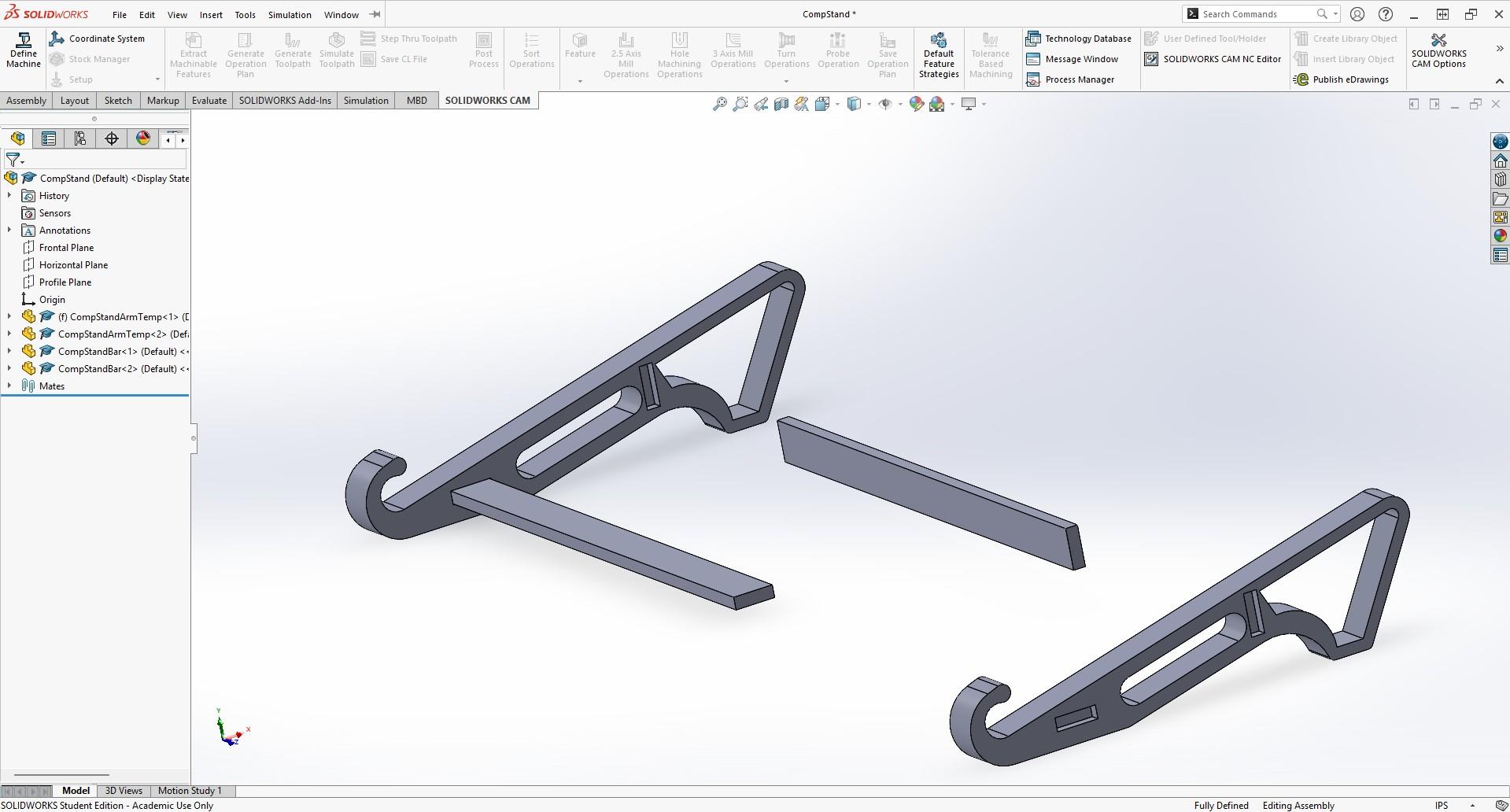
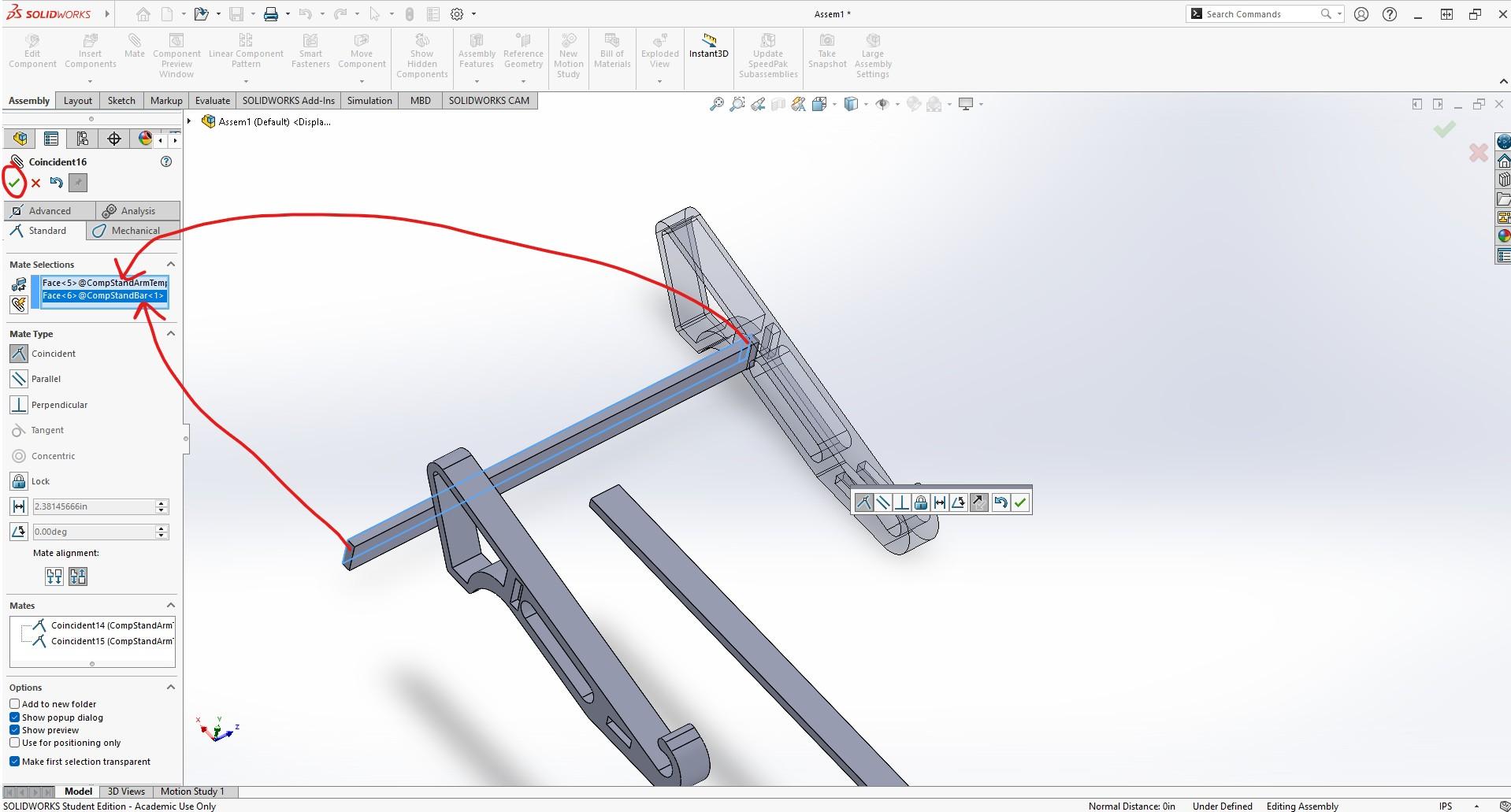
Mating two components creates a geometric relationship between them. To begin adding mates navigate to the Mate button next to Insert Components.
Once this tab has been selected, click on a face from both the Stand Bar and Stand Arm that you wish to have connected to one another. For this assembly you will need each end to be inserted into the sockets cut into the arms.
It is important to note that the first component you place down will be fixed in place. Because of this, it will be much easier to begin creating mates off of this component.
Each time you create a mate make sure to click the green check mark ✓ to save it. Eventually the stand will begin to take shape and each piece shouldnt be able to be moved by your mouse. If parts still move this means you are missing a mate somewhere.
Disclaimer: There will be a bit of open space within the sockets and this is intentional. I found that a bit of space was needed due to the parts not fitting once they were 3D printed. If you do not plan on printing it, editing the components to fit flush will be very simple.
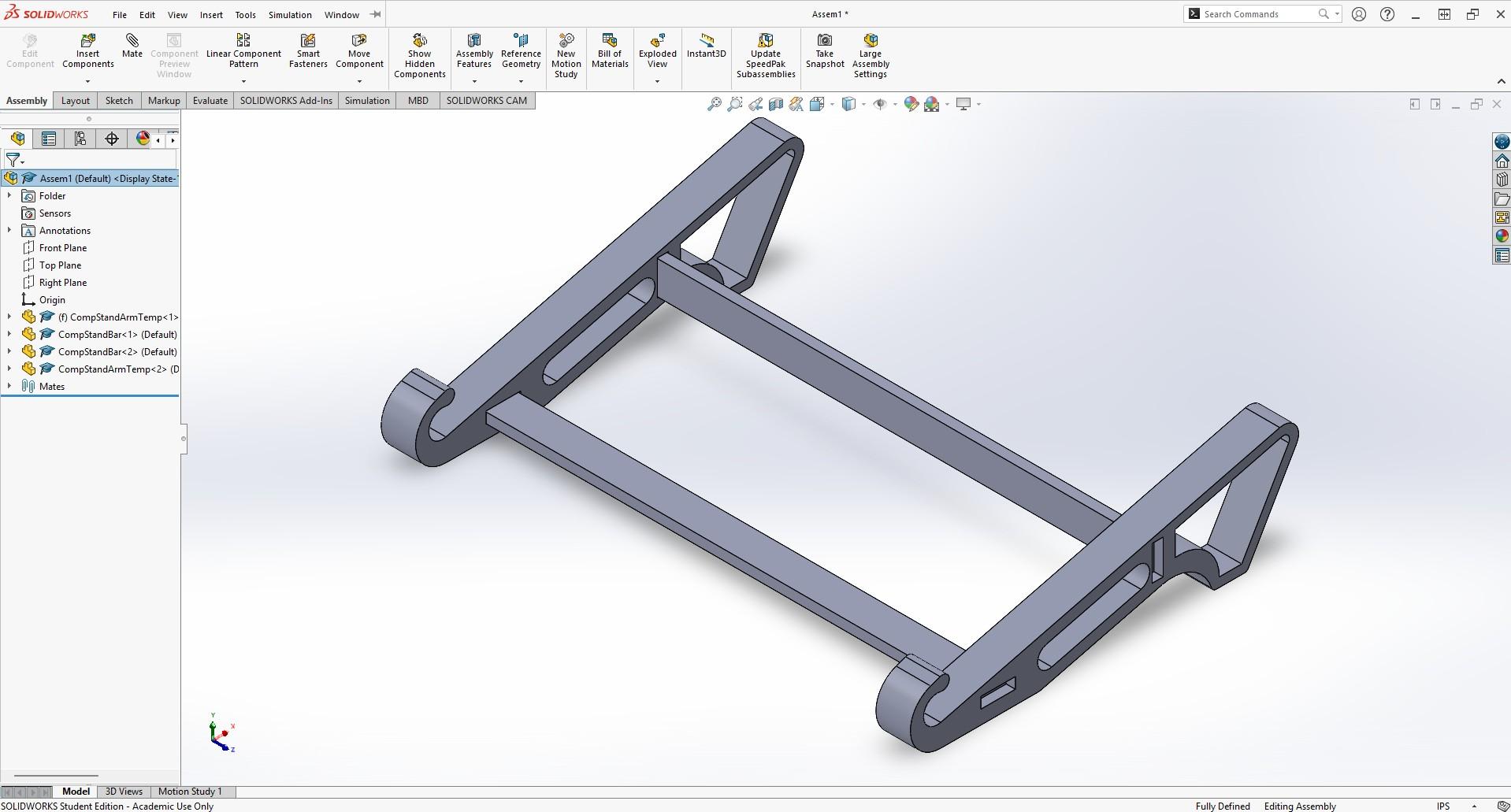
Final View