Control Your Home With Arduino
by Jochefor in Circuits > Arduino
32029 Views, 194 Favorites, 0 Comments
Control Your Home With Arduino

Arduino is a great tool to control and sense thing, this is why most of the people use it, but there is a big catch. Arduino can only handle really small currents. (No more than 40mA). This is ok for some electronic projects, but how do we control big things like a fridge, lights, the coffeemaker, TVs or Computers. This is how:
P.D. From this instructable, you will learn how to control everything in your home that uses below 10A at 125V AC. You don't need to use an Arduino. You can use any Microcontroller you want, from an Arduino Mega to a TI Launchpad, or a breadboard Microcontroller. You can also use a parallel connector directly to a computer to make it work.
If you like this project please visit my blog: https://bioespin.com/
The Basics


- As I said before Arduino only can manage about 40mA. So how we step up the current to manage more current? A good way is to use a relay.
But relays normally use more than 40mA to activate, so we need to use also also a small transistor.
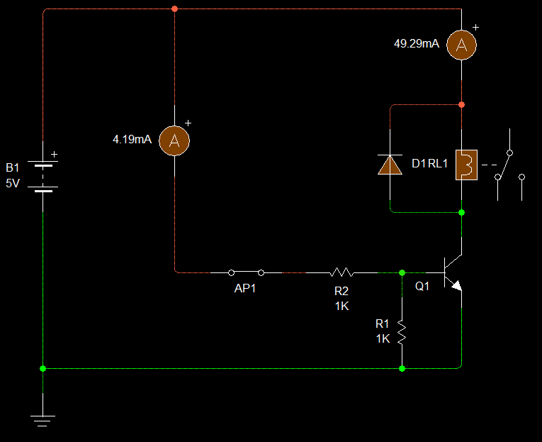
How this circuit work:
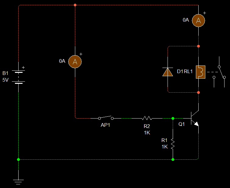
(I simulate the arcuino pin with the AP1 switch.)
- When the arduino pin is LOW the transistor if off, so the relay stays off.
- When the arduino pin is HIGH a small current of 4.19mA flow from the Base to the Emitter of the transistor.
- This activates the transistor and allow a higher current to flow from the Collector to the Emitter, allowing the relay to activate.
- Now a current of 42.29mA can flow directly from a 5V source all the way to Ground.
- And now the relay is activated. So you can control 10A of current at 125V AC.
Relays:
Relays work like a switch that you can activate or deactivate using a electronic signal. If you buy a SPDT relay it's normally going to have 5 pins:
- Common
- NC (Normally Closed)
- NO (Normally Open)
- positive
- negative
- Positive and Negative are the ones that activate and deactivate the relay.
- The common pin is the part of the switch (Relay) that goes to the power source.
- The NC and the NO are the "Outputs". (this is not correct to say but is a lot easier to think in them like that).
- When the Relay is deactivated: the NC pin is closed and anything attached to it its going to be ON. the NO pin is open so anything attached to it its going to be OFF.
- When the Relay is activated: the NC pin is open, anything attached to it its going to be OFF. the NO pin is closed so anything attached to it its going to be ON.
*You can see this in the led images.
The Possibilities Are Endless!!!


Now you can control all you want, from light to a water pump! I ones used this configuration to ignite a rocket and control the rocket's stages, so you can imagine the potential in this circuit. :)
PCB


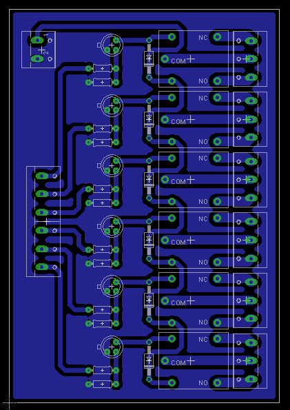
I made a circuit so you can control 6 devices. You can add more relays or make more circuits to control more things. You can download the eagle files below.
Bill of Materials:
6- SPDT relays
6- 2n2222a transistors
6- 1n4004 diodes
6- 1K ohm Resistors
6- 10K ohm Resistors
6- 3 pin Terminal Blocks
1- 6 pin Terminal Block
1- 2 pin Terminal Block
1- 5V Power Source
You can get all components from www.sparkfun.com , http://www.adafruit.com/ or http://www.digikey.com/
Downloads
Conections and Code

Connections:
Just connect arduino from pin 2 to pin 8. Then connect a 5V voltage to the board and that's it.
*Make sure you connect the Power Source Ground to Arduino's Ground.
The Code:
//To make sure our pcb is working well we can use this code. Next you can modify it to you needs.
/********************************************************************/
/*************************Home Control****************************/
int Relay1 = 2;
int Relay2 = 3;
int Relay3 = 4;
int Relay4 = 5;
int Relay5 = 6;
int Relay6 = 7;
/********************************************************************/
// the setup routine runs once when you press reset:
void setup() {
// initialize the digital pin as an output.
pinMode(Relay1, OUTPUT);
pinMode(Relay2, OUTPUT);
pinMode(Relay3, OUTPUT);
pinMode(Relay4, OUTPUT);
pinMode(Relay5, OUTPUT);
pinMode(Relay6, OUTPUT);
}
/********************************************************************/
// the loop routine runs over and over again forever:
//Every Relay its going to activate one second and deactivate one second
void loop() {
digitalWrite(Relay1, HIGH); // turn the Relay on (HIGH is the voltage level)
delay(1000); // wait for a second
digitalWrite(Relay1, LOW); // turn the Relay off by making the voltage LOW
delay(1000); // wait for a second
digitalWrite(Relay2, HIGH); // turn the Relay on (HIGH is the voltage level)
delay(1000); // wait for a second
digitalWrite(Relay2, LOW); // turn the Relay off by making the voltage LOW
delay(1000); // wait for a second
digitalWrite(Relay3, HIGH); // turn the Relay on (HIGH is the voltage level)
delay(1000); // wait for a second
digitalWrite(Relay3, LOW); // turn the Relay off by making the voltage LOW
delay(1000); // wait for a second
digitalWrite(Relay4, HIGH); // turn the Relay on (HIGH is the voltage level)
delay(1000); // wait for a second
digitalWrite(Relay4, LOW); // turn the Relay off by making the voltage LOW
delay(1000); // wait for a second
digitalWrite(Relay5, HIGH); // turn the Relay on (HIGH is the voltage level)
delay(1000); // wait for a second
digitalWrite(Relay5, LOW); // turn the Relay off by making the voltage LOW
delay(1000); // wait for a second
digitalWrite(Relay6, HIGH); // turn the Relay on (HIGH is the voltage level)
delay(1000); // wait for a second
digitalWrite(Relay6, LOW); // turn the Relay off by making the voltage LOW
delay(1000); // wait for a second
}
/**********************************************************************/
Downloads
Ready to Go!

Just add a couple of motion sensors, temperature sensors, door/window sensors, water sensors, etc. and you get a fully automated smart home. I will be uploading how to use this sensor to here and to my website.
If you like this project please enter to my website, I will thank you a lot. https://bioespin.com/ I'm trying to get it running to be able to upload the more open source to the internet.