Controlling LED Blink Speed With Ultrasonic
by Ilan-Haris-Ummath in Circuits > Arduino
1373 Views, 2 Favorites, 0 Comments
Controlling LED Blink Speed With Ultrasonic

This circuit uses Ultrasonic Sensor to measure distance from a nearby object and blinks an LED accordingly. That is, the led will blink more rapidly when the object is closer.
More far the object is, more frequently the LED will blink. More close the LED is, less frequently the LED will blink.
P.S. TinkerCAD simulation below
Supplies

Arduino UNO
Ultrasonic Sensor
LED
Resistor (optional)
Planning Out the Circuit


The circuit is relatively simple.
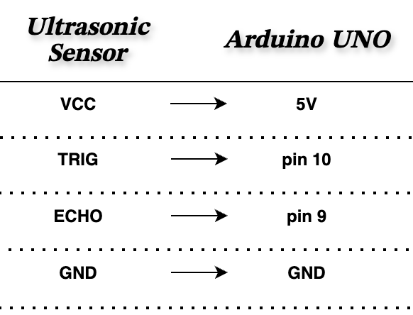
𝐔𝐥𝐭𝐫𝐚𝐬𝐨𝐧𝐢𝐜 𝐒𝐞𝐧𝐬𝐨𝐫
- Positive and negative pins connected to 5v and GND respectively.
- 'trig' and 'echo' pins connected to Digital pins.
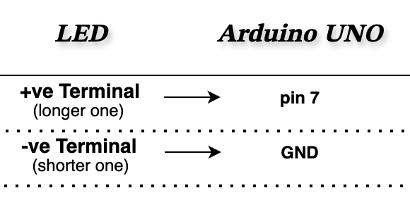
𝐋𝐄𝐃
- Negative pin connected to GND.
- Positive pin connected to digital pin (via resistor, if needed)
Making the Circuit
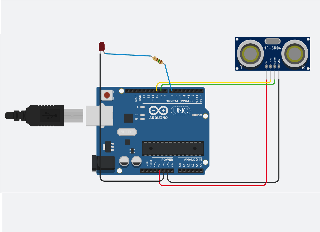
Connect the parts using jumper wires.
Here is the circuit in TinkerCAD:
Programming
Now that we have finished the physical setup of the build, now its time for the code.
This is the main part of the project. This is where we control the LED.
First we need to note down what all our program should do:-
- Read the distance value from Ultrasonic sensor
- Map the distance value with LED blink rate
- Blink the LED
Now let's start writing (or you can use ChatGPT 😁).
This code is pretty straight forward.
𝙲𝚘𝚍𝚎 𝙴𝚡𝚙𝚕𝚊𝚗𝚊𝚝𝚒𝚘𝚗
- First we define some pins and variables.
- In void setup(); we set the pin modes as input/output and initialised serial communication.
- In void loop();
- In the first part, we get distance value from Ultrasonic sensor and prints it on serial monitor.
- Then using an if loop, we set blink interval to be 1800 if distance is greater than 100 cm
- If distance is less than 100cm, we use map(); to map distance value to LED blink rate.
Here 2 to 100 is the range of distance. And 200 to 1500 is the range of blinking. We map the distance from its range to LED's blinking range.
- Then in the last part, we set LED pin to HIGH and waits for a time half the value of blink interval. And then sets LED pin low and again waits half the value of blink interval.
This is done so that within the blink interval, the LED would have turned ON and then OFF, thus completing one full blink.
Testing
Now we test and test and test.
You may want to change the range in
map();
according to your need.
And also the value (100) in this condition:
if (distance > 100){
...
}
Future Integrations
To upgrade this small project, you can change the sensor or even the LED to some other output device(screens, motors, buzzers).
Here's an simulation where I replaced the LED with a Buzzer to create a Vehicle Reverse Alarm System.
This is a prototype of how your car or other vehicles, when in reverse gear, make beep sounds when you're close to hit something.