Convert and Display Color Images on an Arduino TFT Screen
by dziubym in Circuits > Arduino
3613 Views, 6 Favorites, 0 Comments
Convert and Display Color Images on an Arduino TFT Screen


This project demonstrates how to display colorful bitmaps on a TFT screen using an ESP microcontroller. It involves converting images to RGB565 format and transmitting them via serial communication from a PC to the microcontroller, , which then displays them pixel by pixel.
Supplies


We need following two components:
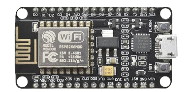
- ESP2866 microcontroller
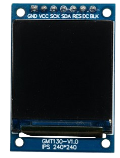
- TFT 240x240 pixels display with ST7789 driver
- PC with Coolterm application and Arduino IDE installed
Sending Bitmap From PC to Microcontroller (Serial Communication)

Here is the brief overview of how his method would work:
- We are having an image on a PC in the RGB565 forma and sending it to the microcontroller via the serial interface (using Coolterm application)
- The microcontroller sketch detects incoming data, reads it two bytes at a time as each pixel is represented by two bytes in RGB 565 format
- Microcontroller outputs the pixel represented by two read bytes to the appropriate place on the display
- The process continous until the whole image is displayed
Connecting Components

We are connecting:
- GND (ESP8266) to GND (TFT)
- VCC (ESP8266) to VCC (TFT)
- GPIO14 (D5 on ESP8266) to SCK (TFT)
- GPIO13 (D2 on ESP8266) to SDA (TFT)
- GPIO12 (D6 on ESP8266) to RES (TFT)
- GPIO15 (D1 on ESP8266) to DC (TFT)
- VCC (ESP8266) to BLK (TFT)
Installing and Setting Coolterm Application


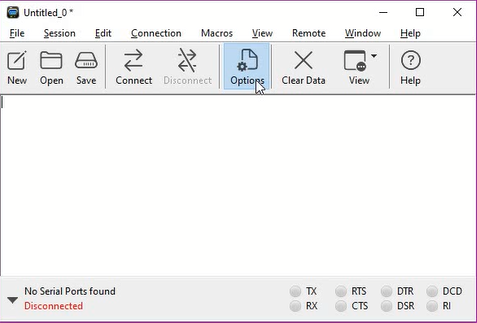
Coolterm application can be easily found in Google. Installation is straight forward.
You can see the configuration setting. It is crucial to use the same baud rate here and in Arduin sketch.
After this setup is completed and microcinbtroller is connected to the PC you can connect the application to ESP2866
Preparing the Image to Display


Here are the steps to prepare the image that can be sent to TFT display:
- Crop and scale down and crop the image so it is 240x240 pixels in size
- Save this image in 24bit color format
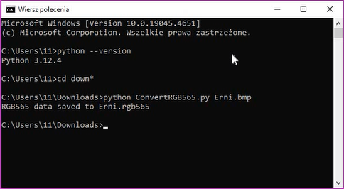
- Run the Python conversion program to convert your image to RGB 565 format
Here is the conversion program:
import argparse
from PIL import Image

def convert_to_rgb565(image_path):
    try:
        # Open the bitmap image
        bitmap = Image.open(image_path)

        # Convert image to RGB mode (in case it's in a different mode)
        bitmap = bitmap.convert("RGB")

        # Get image dimensions
        width, height = bitmap.size

        # Open a file to write RGB565 data
        output_file = image_path.rsplit('.', 1)[0] + '.rgb565'
        with open(output_file, 'wb') as f:
            for y in range(height):
                for x in range(width):
                    # Get RGB color tuple at pixel (x, y)
                    r, g, b = bitmap.getpixel((x, y))

                    # Convert RGB to RGB565
                    rgb565 = ((r & 0xF8) << 8) | ((g & 0xFC) << 3) | (b >> 3)

                    # Write the RGB565 value as 2 bytes (big-endian)
                    f.write(rgb565.to_bytes(2, byteorder='big'))

        print(f"RGB565 data saved to {output_file}")

    except Exception as e:
        print(f"Error: {e}")

if __name__ == '__main__':
    parser = argparse.ArgumentParser(description='Convert a bitmap image to RGB565 format.')
    parser.add_argument('image_path', type=str, help='Path to the bitmap image')
Writing Arduino Sketch to Receive Serial Data
Declaration section:
- we declare the necessary libraries to interface with the display. Then, specify the connected pins and initialize the module.
- we set the display dimensions.
#include <Adafruit_GFX.h>

#include <Adafruit_ST7789.h>

#include <SPI.h>

#define TFT_DC    D1     // TFT DC pin

#define TFT_RST   D2     // TFT RST pin

#define TFT_CS    D8     // TFT CS pin

// Initialize ST7789 TFT module

Adafruit_ST7789 tft=Adafruit_ST7789(TFT_CS,TFT_DC,TFT_RST);

// Constants for bitmap dimensions

const int IMAGE_WIDTH = 240;

const int IMAGE_HEIGHT = 240;
Setup function
- we initialize serial communication with the same baud rate as used in the terminal application.
- we Initialize the display, set the rotation, and clear it.
- we check for any pending data on the serial interface to ensure the image transfer starts with no preceding data.
void setup() {

  Serial.begin(115200);

  delay(1000);


  // Initialize the display

  tft.init(240, 240, SPI_MODE2);

  tft.setRotation(0);

  tft.fillScreen(ST77XX_BLACK); // Clear screen


  while (Serial.available() > 0) {

    // Read incoming byte

    char incomingByte = Serial.read();

    // Do nothing with the incoming data

  }

}
Loop function
- we continuously check for at least 2 bytes available on the serial interface. If available, we read these two bytes (high and low)
- we form a 16-bit color value in RGB565 format out of those two bytes
- we draw this color as a pixel at the current (x, y) position on the TFT display. then we Increment the x position. to move to the next pixel in the current row.
- if the end of a row is reached, we reset x back to 0 and increment y for the next line of pixels. If the end of the image is reached, we wait for 10 seconds and then reset the y position to 0, clear the screen, and we are ready to send and display another image.
void loop() {

  static int currentX = 0;  // Current x position

  static int currentY = 0;  // Current y position

  // Check if there are at least 2 bytes available

if (Serial.available() >= 2) {

      uint8_t highByte = Serial.read(); // read high byte

      uint8_t lowByte = Serial.read();  //read low byte

      // Combine both bytes to form the 16-bit color value

      uint16_t color = (highByte << 8) | lowByte;

      tft.drawPixel(currentX, currentY, color);// draw pixel

      currentX++; // Move to the next pixel

      // If end of the row is reached, move to the next row

      if (currentX >= IMAGE_WIDTH) {

        currentX = 0;

        currentY++;

      }

      // If end of the image is reached, reset for next pic

      if (currentY >= IMAGE_HEIGHT) {

            delay(10000);

            currentY = 0;

            tft.fillScreen(ST77XX_BLACK);

      }

    }

}
Displaying Your Bitmap on the TFT Display

Few final steps to execute:
- load the sketch to microcontroller
- connect the Coolterm application to Microcontroller
- drag and drop the converted image to Coolterm
You will see the progress bar in Coolterm and on TFT you will see the image being displayed line by line.
Conclusion
Hope you find this tutorial useful:)
If you find any info above confusing check the comprehensive video tutorial for this project.
You can find it here: