Converting the Logitech MXERGO Trackball Mouse to USB C
by Solderking in Circuits > USB
3883 Views, 20 Favorites, 0 Comments
Converting the Logitech MXERGO Trackball Mouse to USB C

The MX Ergo is a trackball mouse released by Logitech. I personally love this mouse and plan on using it well into the future.
Unfortunately, this mouse uses a micro-USB port to charge its internal battery, and this is something I don't want to take into the future with me. So, I reverse engineered the power board on the mouse in order to redesign it with USB C instead resulting in a somewhat drop-in replacement. If anyone is wondering, I decided to remake the board so that it could be easier for others to replicate instead of just modifying the original/
This Instructable will walk you through installing the board.
Supplies
You will need the PCB for this mod. You can order one through PCBWay fully assembled or you can order just the board and transfer all the components from the micro-USB board over. If you use it as a transfer board, you will need to purchase the USB C port and resistors R4 and R5. These part numbers can be found in the included BOM file.
Here is a link to my PCBWay community page where you can find the Gerber files and order an assembled or blank PCB
Logitech MX Ergo USB C PCB replacement! - Share Project - PCBWay
A T6 torx and PH00 screwdriver are needed for disassembly and a Dremel or similar file tool is needed for the slight case mods.
Downloads
Video.

This video isn't necessary for the installation of this PCB but it does go a bit more in depth regarding the process involved with coming up with it.
Disassembly




Follow the pictures for the correct order of disassembly.
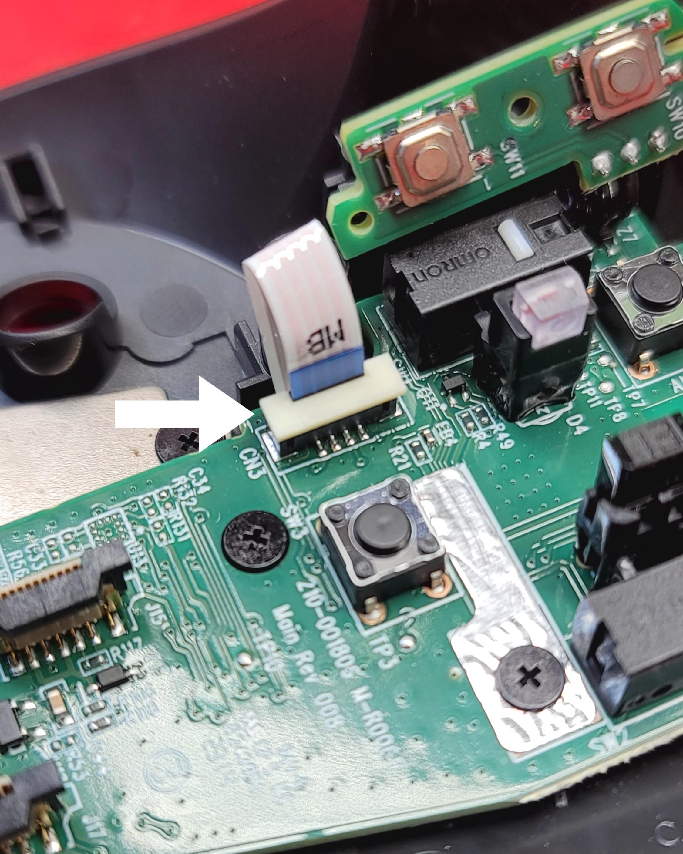
1) (Pic 1) After removing the trackball, remove the 6 T6 screws on the bottom of the mouse. Then carefully open the mouse at the seam. There is a flex cable that connects from the top to the bottom half, and this can be easily damaged with the wrong amount of force.
2) (Pic 2 and 3) Carefully lift up the locking latch on the connector and remove the cable and put the top half to the side.
3) (Pic 4) remove the screw holding this PCB down and move it out of the way to expose another screw.
4) (Pic 5 and 6) Remove the screws for the trackball carriage, lift the locking latch on the connector and put aside.
5) (Pic 7 and 8) Remove the 3 screws holding the battery and disconnect the battery connector. This connection is tight, so I recommend using tweezers to grip the connector while slowly lifting it up. Do not tug on the wires or use the wires to pull the connector out as you may end up damaging it. If you can't remove the connector, you can leave it attached but just be careful with it if you do as you don't want to stress out the wires or accidentally cause a short.
6) (Pic 9 and 10) Remove the scroll wheel. It is just clicked into place so carefully remove it by lifting it out with pressure focused on the right side.
7) (Pic 11 and 12) Lift locking latch for the power board cable connector and remove cable.
8) (Pic 13 and 14) Remove the 4 screws holding the main PCB and put it aside.
9) (Pic 15 and 16) Remove the 3 screws holding the power/switch PCB in place. These 3 screws are shorter than the other Philips head screws so be sure to store them separately.
USB C PCB
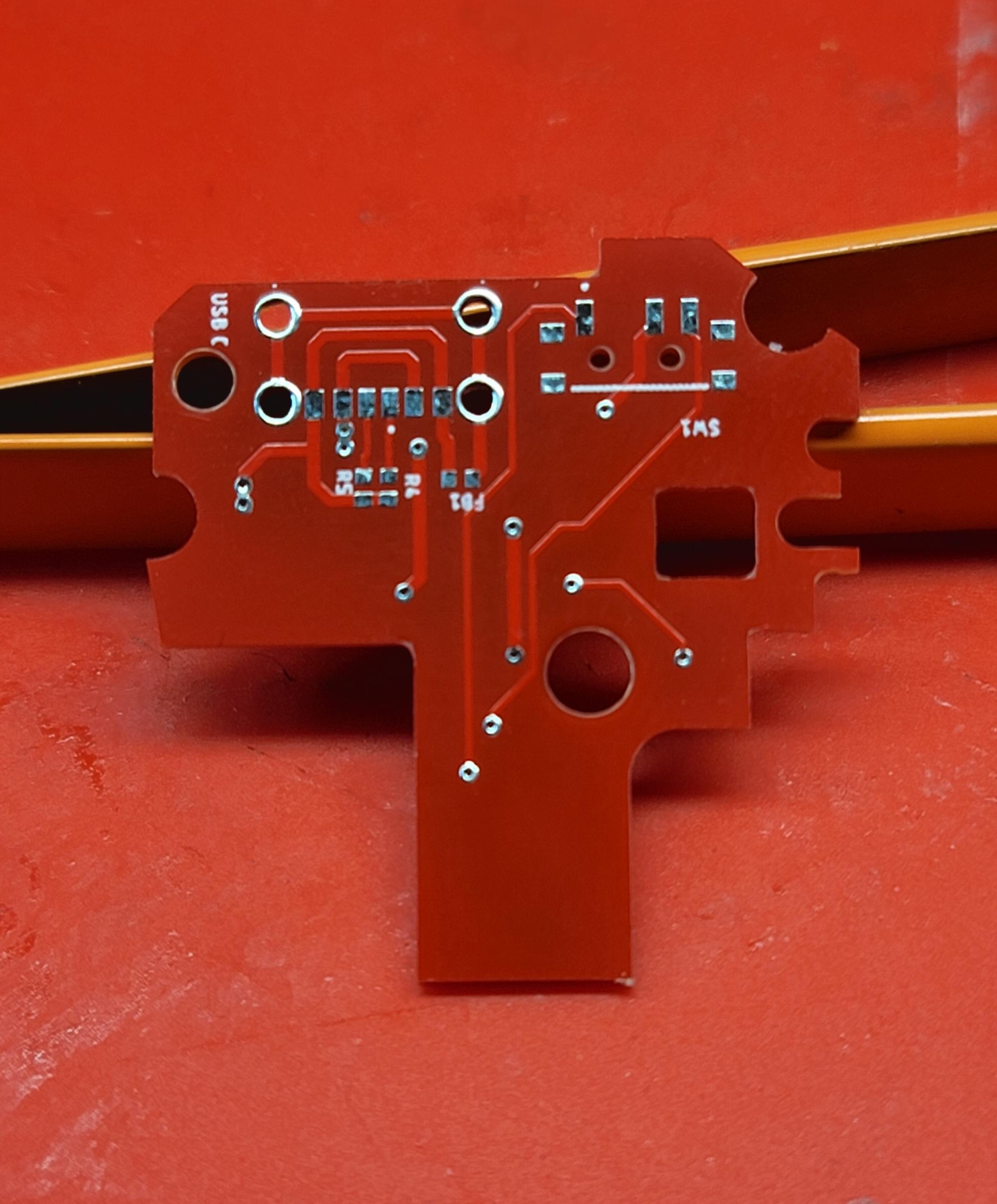


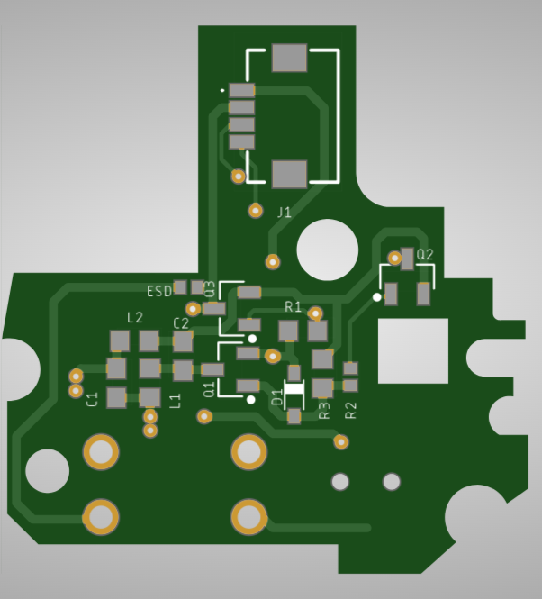
As mentioned, before you can order this PCB fully assembled or you can transfer over the components of the original PCB with a hot air soldering station. I chose to transfer over the components.
The red PCB in this instructable is lacking the ESD traces of the original PCB. I added these traces to the latest revision of the PCB which can be seen in the last two pictures in this step. If you order this PCB you will be ordering the version with the ESD traces.
Modifying the Case.

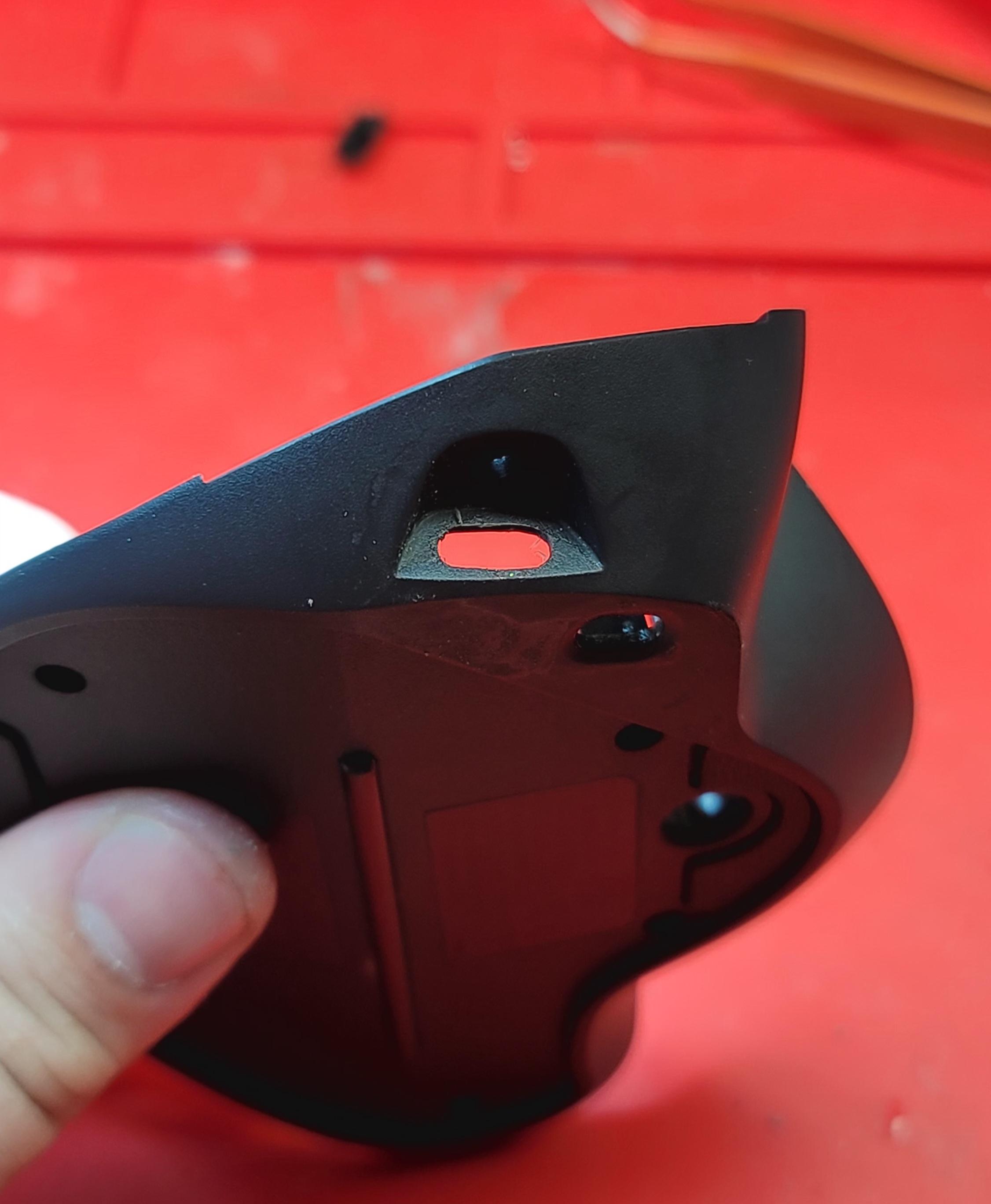

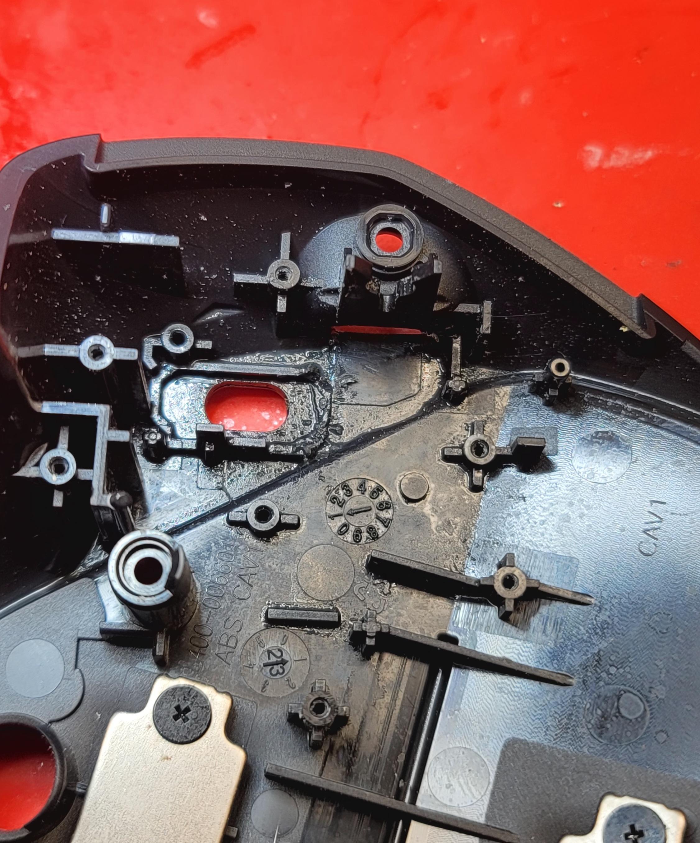

In order to fit the bigger USB port the case has to be slightly modified.
1) (Pic 1 and 2) Use a file or rotary tool to enlarge and round out the micro USB hole to fit the USB C port. Take your time and frequently line up the PCB to check your progress. You don't want to overdo it.
2) (Pic 3 and 4) Remove small amounts of plastic from these areas as shown. The area with the right arrow needs to be very carefully removed as it is thin. If too much is removed, you could go right through the case.
3) (Pic 5) Remove plastic tabs from switch cover. These may bump into the bigger port and cause switch issues.
Installing New PCB


Following the case modifications the PCB should sit flush and move somewhat freely back and forth. Compare the movements with the original PCB to get a feel for it.
Make sure the plastic switch cover matches slide switch before screwing the PCB down. You may have to move the PCB around to better engage the switch as the holes I used in the USB C PCB are slightly bigger than the original ones. Do a few test fits while moving the switch to make sure that the plastic switch cover is aligned and actuating correctly.
Finished.


Now once the battery dies every few months you can reach for your closest USB C cable and charge your mouse without having to rummage around for a micro USB.