Crenux Truck: Custom ESP32 Web-Controlled Mercedes-Benz RC Truck
by Bogdan Bulat in Circuits > Electronics
153 Views, 2 Favorites, 0 Comments
Crenux Truck: Custom ESP32 Web-Controlled Mercedes-Benz RC Truck
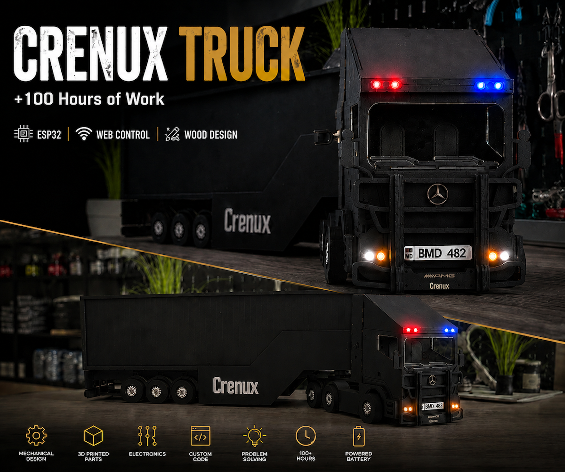
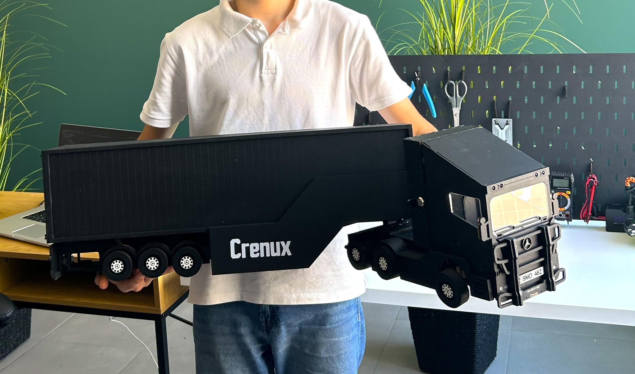
100+ hours. 3,000+ lines of code. One goal: build the ultimate web-controlled wooden Mercedes-Benz truck powered by an ESP32.
Hello, Maker community! My name is Bogdan Bulat, I am a 13-year-old self-taught maker, and this is the Crenux Truck. This is my most ambitious project yet: a custom-built, web-controlled Mercedes-Benz RC truck featuring a hybrid laser-cut plywood chassis, 3D-printed mechanical components, and an embedded web dashboard hosted entirely on an ESP32 microcontroller—accessible from any browser without installing any apps.
This project represents over 100 hours of continuous work divided into vector design, 3D printing, electronics troubleshooting, and firmware programming. Along the way, I faced real-world engineering challenges, such as adapting a 3mm-focused structural design to 4mm plywood, and completely redesigning the drivetrain when the wooden gears couldn't handle the motor's torque.
To give you an idea of the engineering scale and development process behind the Crenux Truck, here is a quick breakdown of what went into this build:
- 100+ Hours of total development, split between vector design, 3D printing fixes, electronics assembly, and firmware optimization.
- 3,000+ Lines of Code written across the final ESP32 firmware and the responsive HTML/JS web dashboard to ensure zero-latency control.
- 20+ Different Code Versions created from scratch to test individual features, from basic Wi-Fi access points to multi-threaded loops.
- 10+ Separate Test Code Files (.ino) compiled exclusively to benchmark hardware limits, sensor stabilization, and WebSocket packet speeds.
- 70+ Precision Parts custom-engineered, including interlocking laser-cut plywood structures and mechanical upgrades.
- 15+ Electronic Components integrated seamlessly inside the cabin, from power regulators to advanced state-machine lighting.
- 1 Hour and 30 Minutes of highly optimized 3D printing time to fabricate the heavy-duty transmission gear train using high-density PLA filament.
Supplies
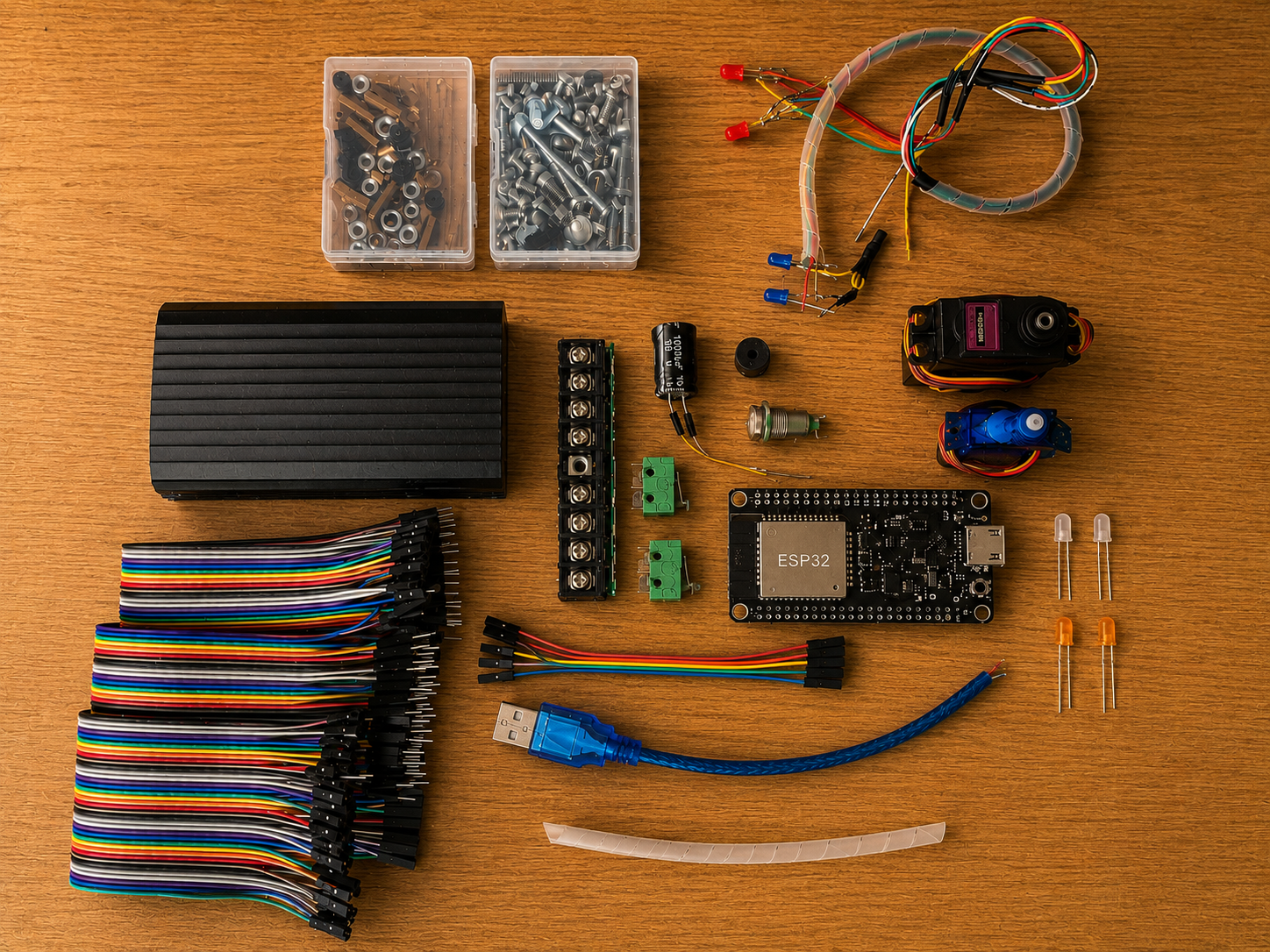
To build the Crenux Truck, you will need a mix of electronic components, hardware fasteners, and raw materials for digital fabrication. Below is the complete Bill of Materials (BOM) with recommended links to source high-quality components for this engineering project.
1.ESP32 DevKit V1 (30 pins)
2.MG996R Servo Motor (High Torque)
3.SG90 Servo Motor (Steering)
4.Mechanical Limit Switches (Endstops) x2
5.Passive Piezoelectric Buzzer
6.Metal Ignition Key Switch
7.Red LEDs x2
8.Blue LEDs x2
9.White LEDs x2
10.Orange / Amber LEDs x2
11. 220 Ohm Resistors (For LEDs protection) x8
12. 1000uF 6.3V Electrolytic Capacitor
13. 8-Position Terminal Block Barrier Strip
14.Jumper Wires Dupont Cables
15.Power Bank (5V)
16.M3 and M4 General Machine Screws and Nuts
17. 4mm Plywood Sheet (120x90 and 70x50 cm)
18.Matte Black Acrylic Paint (For Brush Application)
19. 1.75mm PLA Filament (Green and White Colors)
Chassis Design in Adobe Illustrator
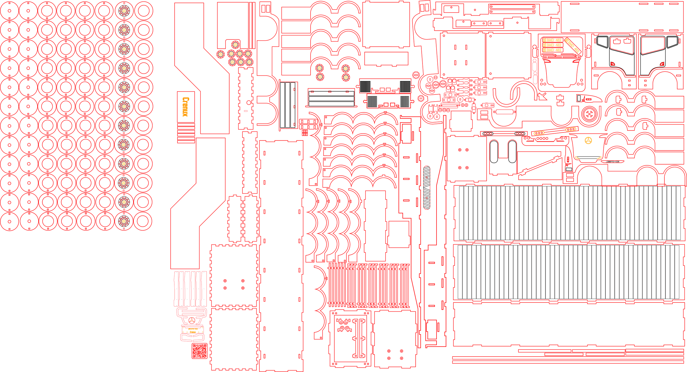
Everything started with a base vector design purchased from an Etsy.com store, which I then completely modified and re-engineered in Adobe Illustrator to suit the mechanical needs of this specific project.
If you want to check out the original base files I started with, you can support the creator and find them here:
The heavily modified layout was optimized to maximize the working area of a standard 70x50 cm CO2 laser cutter. Designing parts for laser cutting requires a completely different mindset than 3D modeling, as you must strictly account for mechanical tolerances.
Key Laser Design Modifications:
Thickness Adaptation (3mm to 4mm): The original Etsy blueprint layout was intended for 3mm plywood. Because I used 4mm plywood sheets, I had to manually recalculate every single tab width, slot depth, and kerf tolerance across the entire vehicle layout. A 1mm thickness change accumulates across every interlocking wall, so it required a thorough component-by-component redesign rather than a simple file scaling.
Kerf Compensation: The laser beam burns away a small fraction of material (the kerf). Every single interlocking joint was adjusted by micro-millimeters to ensure the pieces wouldn't fit too loosely.
Finger Joints: The chassis relies on interlocking tab-and-slot joints. By adjusting these perfectly for the 4mm wood, the chassis gained massive structural rigidity without relying on external metallic brackets or visible screws.
Nesting: All modified components were nested carefully across the sheet layout to minimize material waste and optimize laser travel time.
👇Download the Chassis Vector Files
Downloads
Laser Cutting & LightBurn Setup
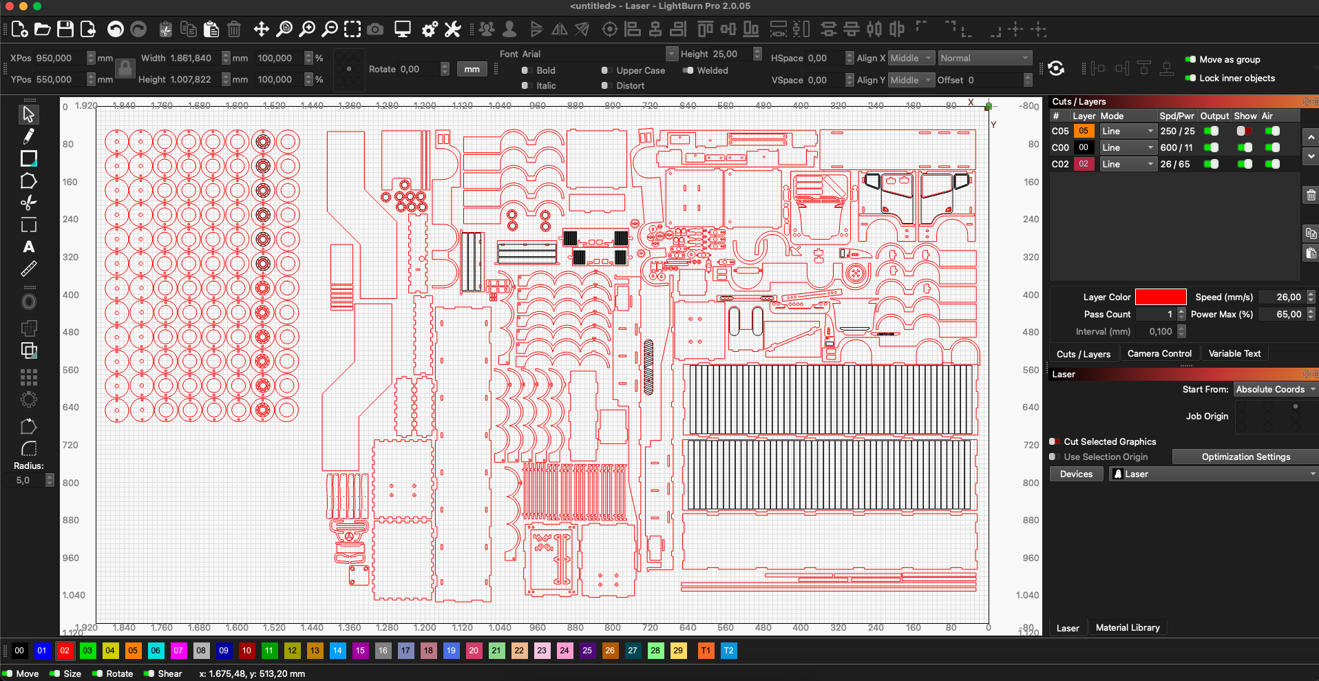
With the vector file completely optimized and adjusted for 4mm plywood, the layout was imported into LightBurn software and sent to a professional OMTech 70x50 cm CO2 laser cutter (60-80W).
To orchestrate the fabrication process efficiently, I organized the design into distinct color-coded layers within LightBurn. Each color dictates a specific laser mode, speed (measured in mm/s), and power percentage to achieve precise results without burning the wood:
Red Layer (Cutting): Used for cutting out the external profiles and slots of the chassis components. This layer requires maximum power and a slower speed to penetrate the 4mm plywood entirely in a single pass.
Black Layer (Line Drawing / Scoring): Used for vector scoring or tracing superficial alignment lines on the chassis. This utilizes high speed and low power, allowing the laser to quickly mark the surface without cutting through.
Orange Layer (Engraving): Used for raster engraving deep text, details, and logos. The software moves the laser head rapidly side-to-side, tuning power and speed to burn away precise layers of wood for a clean contrast.
This stage is the ultimate test for your kerf and tolerance calculations. If your LightBurn parameters and material testing are correct, the tabs will fit into the slots tightly under friction. This ensures the structural chassis won't wobble, eliminating the need for excessive mechanical force that could fracture the wood fibers during assembly.
👇Download the LightBurn Laser Project
Downloads
Mechanical Dry-Assembly
Before applying any permanent adhesives or finishes, the entire structural chassis was completely dry-assembled. This means fitting every single interlocking piece together in its raw form to double-check that the overall 3D geometry aligns perfectly.
This is a critical engineering checkpoint: any vector design flaws, misaligned slots, or structural tolerance stack-ups are detected here, where it is still easy and cost-effective to re-cut a single corrected component rather than wasting an entire painted assembly.
Sanding and Painting
Once the structural geometry was verified, the chassis was disassembled, lightly sanded, and completely painted using a brush application of high-quality matte black acrylic paint. This styling choice moves the aesthetics away from the typical "wooden hobby kit" look of raw plywood, giving the Mercedes-Benz truck a rugged, industrial, and heavy-duty look.
💡 Maker Tip: When painting laser-cut plywood, always sand down the charred, burnt edges left by the CO2 laser beam before applying your paint. The carbonized wood layer prevents paint from absorbing evenly, which can cause ugly patches and premature peeling if the surface is not properly prepared.
Drivetrain Redesign — From Laser-Cut Wood to 3D Printing
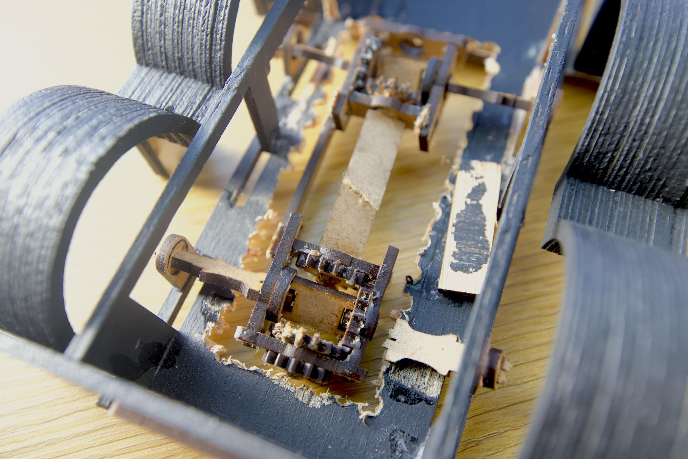
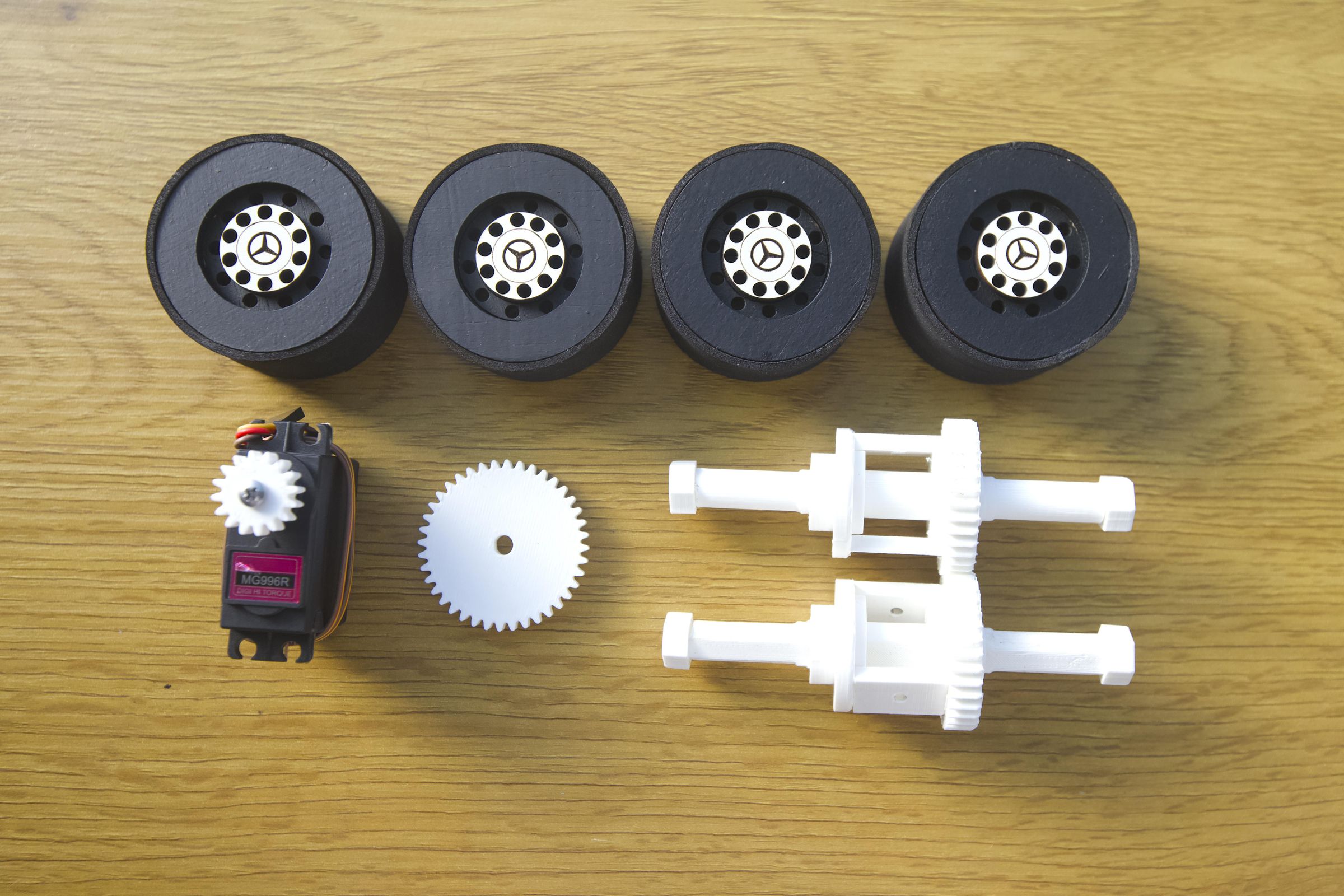

The first functional iteration of the truck's drivetrain—including the internal gears and transmission axles—was fabricated entirely out of laser-cut plywood. However, during early stress tests, the high torque generated by the traction motor combined with continuous tooth-to-tooth friction quickly overcame the structural integrity of the wood grain, causing the gear teeth to shear and fracture completely.
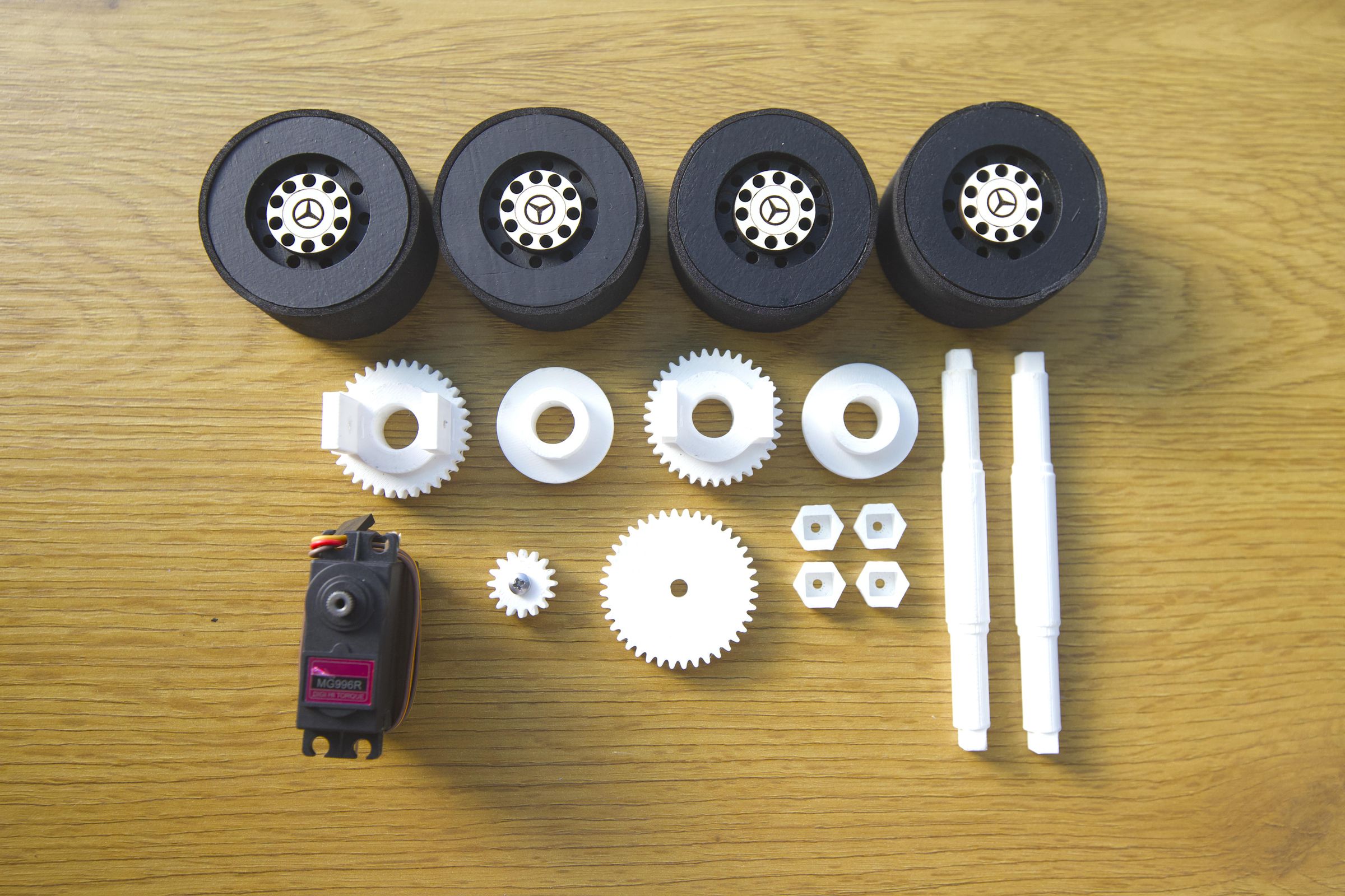
To solve this mechanical failure, I redesigned the entire gear train and transmission assembly from scratch to be 3D printed using high-density PLA filament.
Why 3D Printing Saved the Drivetrain:
High Fatigue Resistance: Unlike plywood, which splits along its natural grain layers, 3D-printed plastic handles multidirectional mechanical loads and continuous friction significantly better.
Tighter Tolerances: 3D modeling allowed me to implement optimized tooth profiles, reducing gear backlash and ensuring smoother mechanical power transfer.
Modular Maintenance: If a single component wears out, I can simply re-slice and reprint that specific part instead of having to cut a whole new sheet of plywood.
The newly engineered assembly features the main drive gear, a custom pinion gear coupled to the high-torque MG996R servo, low-friction reduction bushings, and heavy-duty drive axles. The entire 3D-printed system was engineered to drop directly into the existing laser-cut side-frame mounting points, meaning the internal mechanics were fully upgraded without requiring any modifications to the external chassis design.
Slicing Warning: Some pieces, like the differentials, have parts that print in the air. You **must enable supports** in your slicer for these specific parts to print correctly!
👇Download the 3D Printing Files
Full Hardware Wiring and Assembly Guide
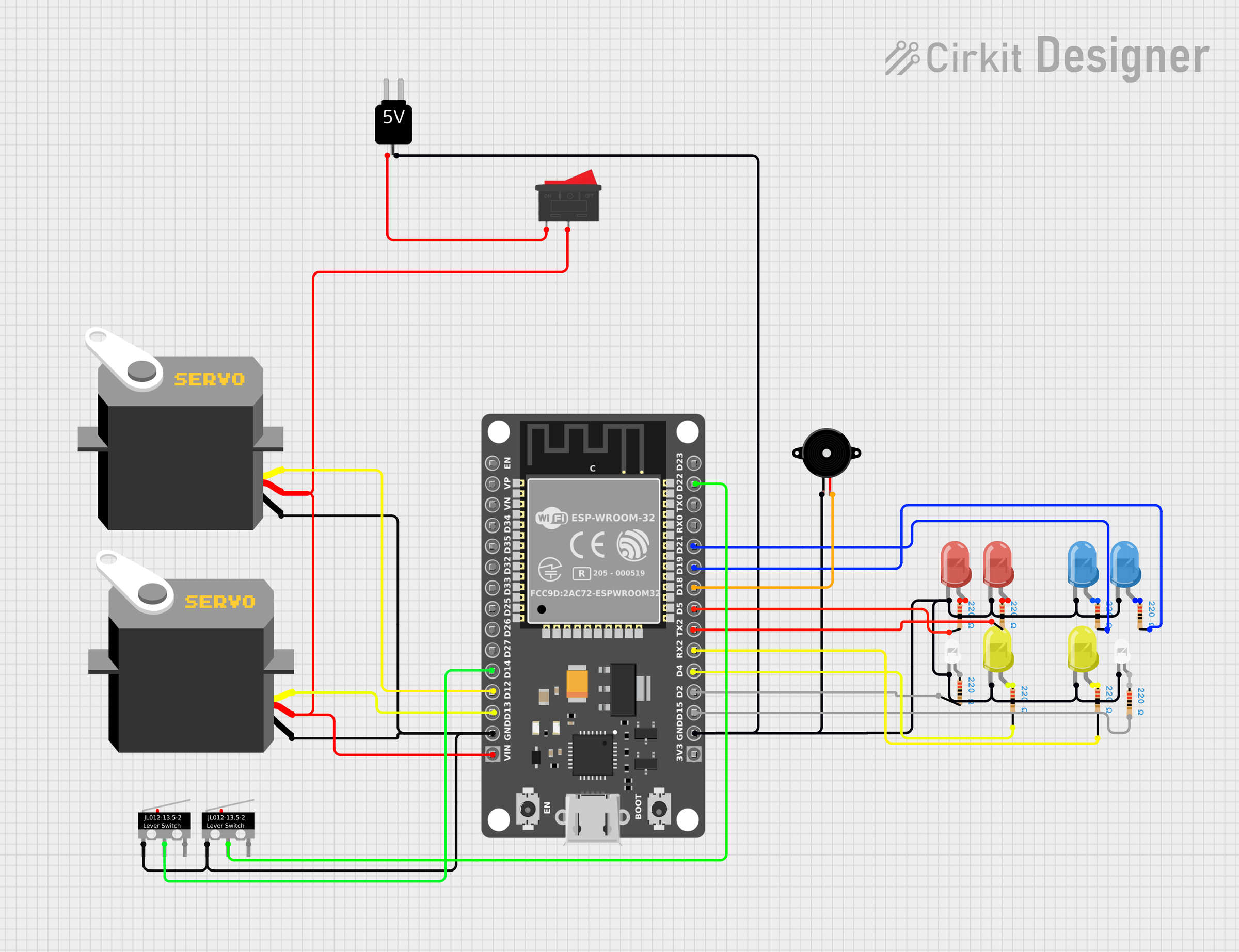
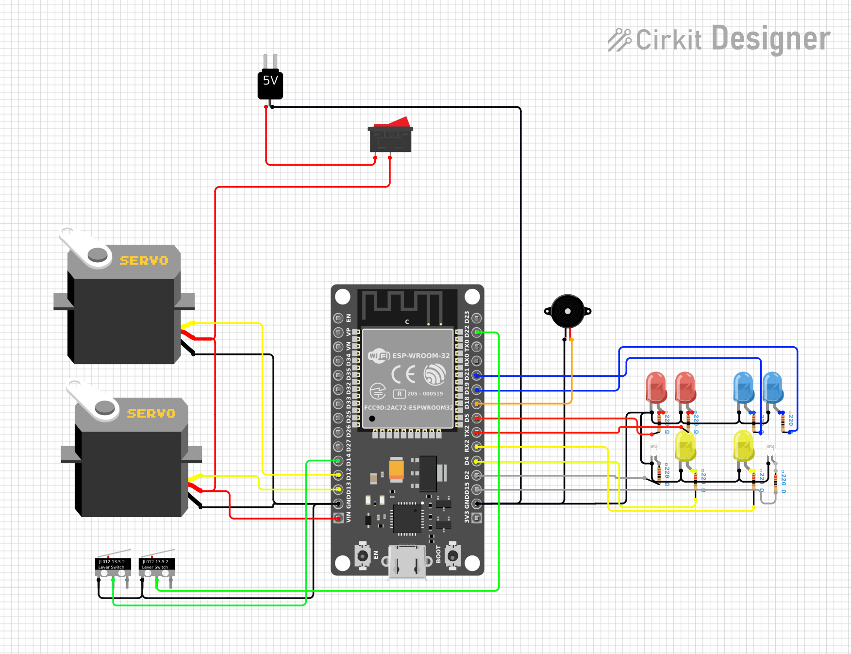
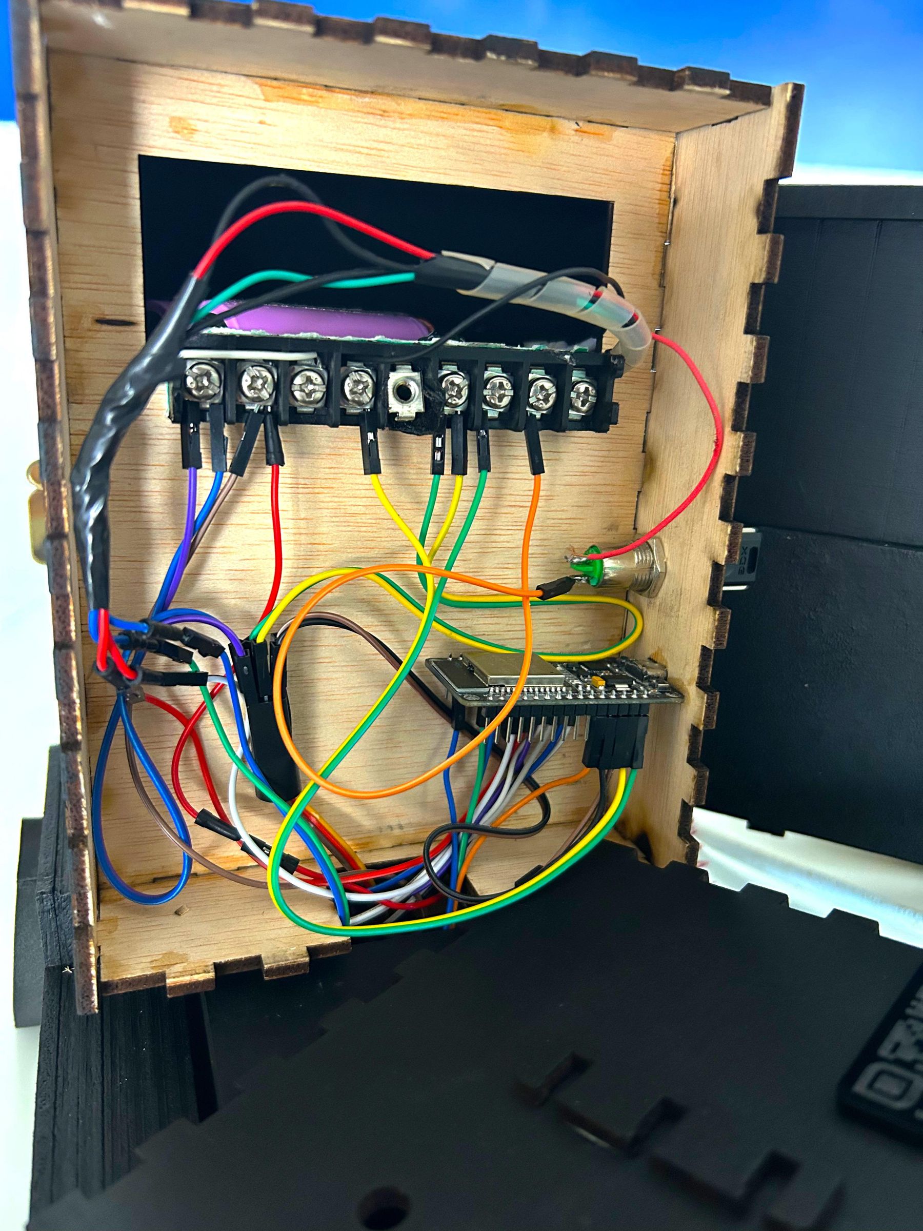
With all the 3D-printed parts ready, it is time to connect the electronics. To make the truck as compact and robust as possible, all components should be placed as close to each other as physics allows, minimizing wire clutter and avoiding tangled nests inside the chassis.
Critical Wiring Rules:
Before turning on the power switch, make sure your circuit follows these essential safety and engineering guidelines:
- Common Ground (GND): All negative wires from the battery, ESP32, servos, buzzer, and LEDs must connect to a shared ground rail. A unified ground ensures clean signal communication across the entire vehicle.
- LED Protection Resistors: Never connect a LED directly to an ESP32 pin! Every single one of the 8 LEDs requires a 220-Ohm resistor connected in series with its long pin (Anode) to limit current and prevent burning out the chip or the LED.
- Alternative Pin Labels: Keep in mind that some ESP32 DevKit V1 manufacturers do not label pins numerically. For instance, GPIO 16 is labeled as RX2, and GPIO 17 is labeled as TX2. Refer to the list below to avoid miswiring.
Complete Pin Mapping Reference:
- MG996R Servo (Rear Drivetrain Traction): Connects to GPIO 12.
- SG90 Servo (Front Steering Linkage): Connects to GPIO 13.
- Left Endstop (Safety Stop Trigger Left): Connects to GPIO 14.
- Right Endstop (Safety Stop Trigger Right): Connects to GPIO 22.
- Piezo Buzzer (Horn and Emergency Sirens): Connects to GPIO 18.
- White LED Left (Front Left Headlight): Connects to GPIO 15.
- White LED Right (Front Right Headlight): Connects to GPIO 2.
- Orange LED Left (Left Turn Signal / Hazard): Connects to GPIO 4.
- Orange LED Right (Right Turn Signal / Hazard): Connects to GPIO 16 (labeled as RX2).
- Police Red LED 1 (Emergency Patrol Light): Connects to GPIO 17 (labeled as TX2).
- Police Red LED 2 (Emergency Patrol Light): Connects to GPIO 5.
- Police Blue LED 1 (Emergency Patrol Light): Connects to GPIO 19.
- Police Blue LED 2 (Emergency Patrol Light): Connects to GPIO 21.
Downloads
Arduino Code Technical Breakdown
The following sections explain the most important parts of the firmware. The complete source code is available for download below.
1. LIBRARIES
ESP32Servo drives the steering servo and the traction motor (handled as a
continuous-rotation servo). Preferences stores the steering calibration in
non-volatile memory so it survives a reboot. WiFi + WebServer create the
access point and serve the dashboard. WebSocketsServer handles the
real-time channel that carries driving commands.
2. NETWORK AND PIN SETUP
The web server runs on port 80, the WebSocket on port 81 — separate
channels so the browser can load the HTML page while keeping a
low-latency link open just for driving commands. All pins are named
constants instead of raw numbers, so the rest of the code reads by
meaning, not by GPIO number.
3. GLOBAL STATE VARIABLES
Everything the truck is currently doing lives in these globals. They're
not "button pressed right now" flags — they stay true until the opposite
command arrives, which is what lets you hold "accelerate" without
resending it every cycle. power/tpower are the current vs. target motor
power, used for the acceleration ramp.
4. COMMAND WATCHDOG (FAILSAFE)
The dashboard resends each movement command every 150 ms as a heartbeat.
If no new heartbeat arrives within 300 ms — dropped WiFi, frozen tab,
backgrounded browser — the firmware cuts that movement on its own,
without waiting for an explicit "stop" command that might never come.
5. SOUND: THE BUZZER
Every sound — horn, siren, turn-signal tick, reverse beep — goes through
these two functions, driving the same PWM pin at different frequencies.
No audio files, just tone generation. buzzTone sets a 50% duty cycle
(128/255) and writes the requested frequency; buzzOff silences it.
6. STEERING CALIBRATION AND CONTROL
Lmin/Rmax/Cmid are the three calibrated angles: left limit, right limit,
center. servoRawWrite moves the servo with no limit checks; servoWriteSafe
clamps to [Lmin, Rmax] first, so normal driving can never force the servo
past its calibrated stops. STEERING_REVERSED is the fix for left/right
turning the servo the same way: if the servo ends up physically mounted
backwards, flipping this one constant to true corrects it everywhere.
save()/load() persist calibration via Preferences. load() also validates:
if any saved value is out of range, or the gap between limits is under
20°, it discards everything and falls back to defaults — so the truck
never boots with a corrupted or near-unusable calibration.
These back the "STEERING SERVO ADJUSTMENT" buttons. manualServoStep moves
the servo freely (bypassing safe limits) and blocks automatic steering
for 8 seconds so it doesn't fight the calibration buttons. The set*
functions save the current angle as a new limit; goCenterNow recenters
with a shorter 3-second block, used e.g. on disconnect.
Called every loop tick. Skips entirely during manual calibration or if
less than 20 ms passed since the last move. The turn step scales with
driving mode (2° in Eco, 5° in Race). With no turn key held, the servo
eases back to center 2° at a time — an automatic self-centering steering
feel.
7. SETUP()
Runs once on boot, in this order: configure pins, attach the buzzer PWM
channel and both servos, load and immediately apply the saved steering
calibration before anything else touches the servo, then start the WiFi
access point, the HTTP server (serving the embedded HTML dashboard), and
the WebSocket. The onEvent handler is where every dashboard button
arrives: on disconnect it resets all movement/light state and recenters
steering; on a text message it matches the command string and flips the
matching state variable, or calls a calibration function directly.
8. LOOP() — THE MAIN CYCLE
Three calls run on every single pass, with no timing filter, because any
delay here adds directly to perceived control latency: handling pending
HTTP requests, processing WebSocket messages, and running the command
watchdog. Everything else — motor, steering, lights, sound — only runs
inside a block gated to once every 25 ms, giving a fixed 40 Hz update
rate independent of how fast loop() itself spins.
POWER AND DRIVING MODES. Each mode sets its own max power, acceleration
and braking rate. Target power (tpower) is 0 if the engine is off or
parked, mp if driving forward, a fixed -0.78 if reversing (always capped
below forward speed, on purpose). Actual power (power) ramps toward that
target step by step instead of jumping instantly — a progressive start
that also protects the 3D-printed gears.
STEERING. Calls the function from section 6 — moves the servo toward the
requested direction, or eases back to center if no turn key is held.
HEADLIGHTS. The simplest block: both LEDs on/off directly from the light
flag, no blinking, no extra logic.
POLICE LIGHTS. A counter (pStep) cycles 0→3 every 150 ms; reds are on
while pStep is 0–1, blues while it's 2–3, giving the classic alternating
red/blue flash. All four LEDs are explicitly turned off when police mode
isn't active.
TURN SIGNALS. hState flips every 400 ms as the shared blink clock. Both
sides blink together if hazards are on OR the truck is reversing — that's
what makes reverse gear automatically trigger both signals, like a real
truck's reverse lights. Otherwise only the requested side blinks.
SOUND. A priority chain, only one branch runs per cycle: horn always wins
(520 Hz); then police siren, alternating 880/620 Hz on the same pStep
that drives the lights, so sound and flash stay in sync; then an
automatic reverse beep (900 Hz every 500 ms); then a turn-signal tick
(800 Hz every 400 ms); otherwise silence, resetting iState.
WHY IT'S STRUCTURED THIS WAY
Global state flags describe what the user wants; the 25 ms loop tick
turns that into real signals (PWM, servo angle, LEDs, buzzer tone).
Every safety mechanism — command watchdog, disconnect handling, servo
limits — defaults to "stop and center" if communication or logic breaks,
never "keep doing the last thing forever."
👇Download the ESP32 Code
Downloads
Connecting to the Web Dashboard
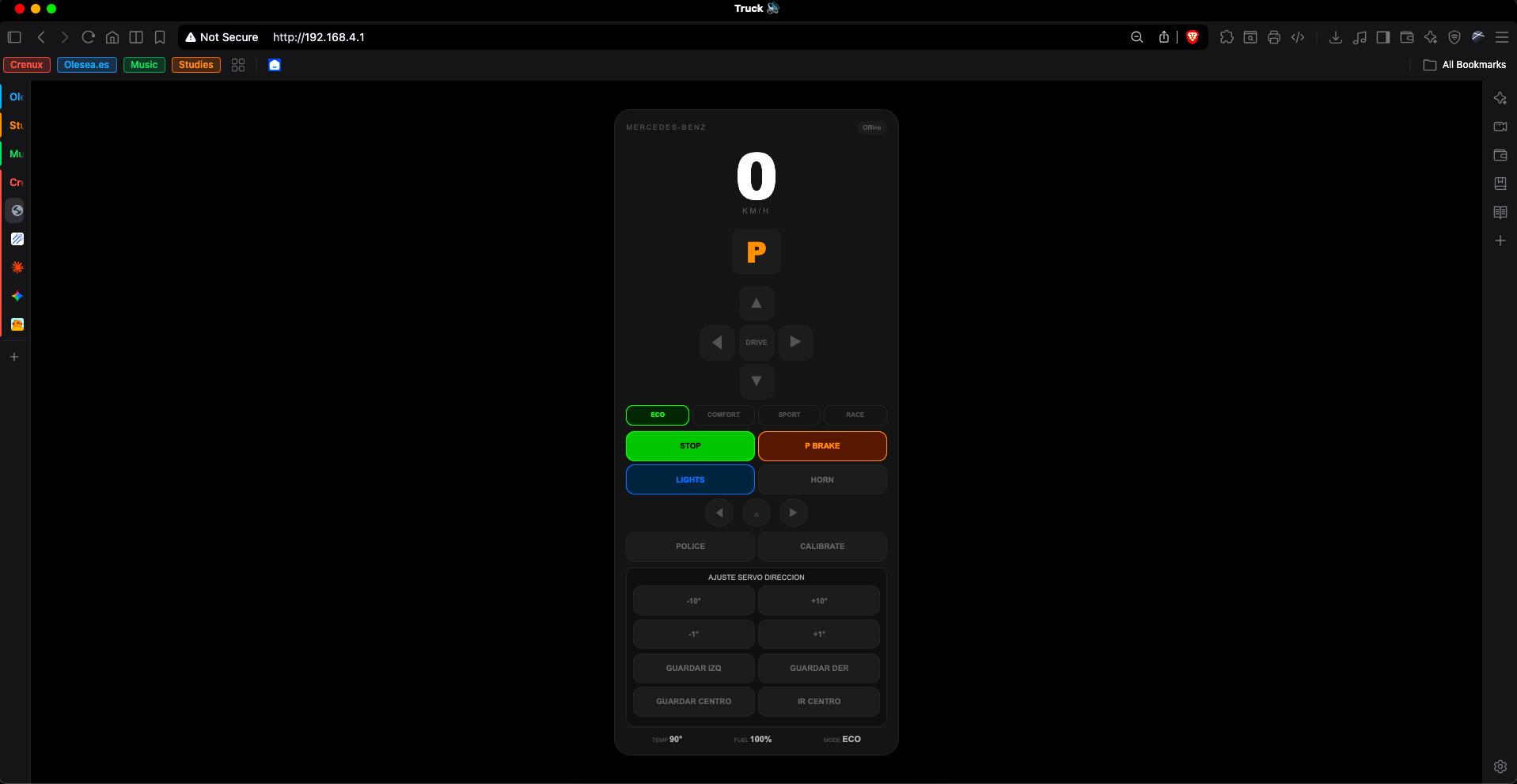
Here's exactly how any phone or computer ends up controlling the truck, with zero apps to install.
1. POWERING UP AND FINDING THE NETWORK
As soon as the ignition key switch is turned and the ESP32 boots, it does NOT try to join your home WiFi. Instead, it creates its own wireless network by running in Access Point (AP) mode:
This means the truck is the network. On your phone's WiFi settings, you'll see a new network appear:
Network Name (SSID): Crenux-Truck
Password: MyCrenuxTruck
Connect to it just like you would connect to any other WiFi network. There's no internet access through this network — it exists purely so your phone and the ESP32 can talk to each other directly, with no router in between.
2. FINDING THE TRUCK'S IP ADDRESS
Once connected to the Crenux-Truck network, the ESP32 is reachable at a fixed default address for any device in Access Point mode:
Open any browser (Safari, Chrome, whatever you have) and type that address into the URL bar. The ESP32's WebServer instance is listening on port 80 (standard HTTP), so you don't even need to type a port number.
3. LOADING THE DASHBOARD
When the browser requests the root path ("/"), the ESP32 responds with the entire dashboard — HTML, CSS, and JavaScript — sent directly from a PROGMEM constant baked into the firmware itself. There's no SD card, no external file system, no separate web files to upload: the whole interface lives inside the .ino sketch. The no-store/no-cache headers make sure your browser always loads the current version instead of a stale cached copy from a previous firmware upload.
4. THE REAL-TIME CONNECTION (WEBSOCKET)
Loading the page is only half the story. As soon as the dashboard's JavaScript runs, it opens a second, persistent connection on port 81:
This is the WebSocket link, and it's what makes the controls feel responsive instead of laggy. A normal web request has to open a new connection, send data, and close it every single time — noticeable overhead if you're doing it 6+ times a second while driving. The WebSocket instead stays open the whole session, so every button press is just a tiny text message sent instantly over an already-established pipe.
The status indicator in the top corner of the dashboard reflects this connection directly: it shows "Offline" until the WebSocket handshake completes, then flips to "Online" the moment it's ready to accept commands.
5. WHAT HAPPENS WHEN YOU PRESS A BUTTON
Every control on the dashboard — the D-pad, START, P BRAKE, LIGHTS, HORN, the driving mode buttons, the turn signals, POLICE, and the steering calibration buttons — sends a short text command over that WebSocket connection ("F" for forward, "policia" for the siren, "modeSport" for Sport mode, and so on). The ESP32's onEvent handler (covered in Step 7) receives that text and flips the matching state variable in the firmware.
While a directional button (forward/back/left/right) is held down, the dashboard doesn't send the command just once — it resends it every 150 ms as a heartbeat, which is exactly what the command watchdog from Step 7 relies on to detect a lost connection.
6. WHAT HAPPENS WHEN THE CONNECTION DROPS
If you close the browser tab, walk out of WiFi range, or your phone locks itself, the WebSocket disconnects. The ESP32 detects this immediately (WStype_DISCONNECTED) and reacts on its own: every movement and light state is forced back to off, and the steering servo automatically returns to its calibrated center. You never end up with the truck stuck mid-turn or mid-throttle just because the phone lost signal.
On the browser side, the dashboard also detects the drop and automatically retries the connection every 2 seconds, so reconnecting is as simple as walking back into range — no need to reload the page.
7. QUICK CONNECT WITH THE QR CODE
To skip typing the SSID and password by hand every time someone new wants to try the truck, I engraved a QR code directly into one of the laser-cut chassis panels (see the vector file from Step 1). Scanning it with any modern phone camera triggers the same WiFi join prompt as typing the credentials manually — it's just a shortcut, not a different connection method.
8. KEYBOARD SHORTCUTS (DESKTOP USE)
If you're testing from a laptop instead of a phone, the dashboard also listens for keyboard input, so you don't have to click on-screen buttons for every action:
This is purely a convenience layer for bench testing — the WebSocket commands sent are identical to the ones triggered by tapping the on-screen buttons.
Acrylic Details & Finishing Touches
With the chassis painted, the drivetrain solved, all the electronics wired, and the firmware running, the last stage was adding the small details that make the Crenux Truck actually read as a Mercedes-Benz truck instead of just a black box on wheels.
Transparent Acrylic for Windows: The cab windows and windshield are cut from a clear acrylic sheet, sized to drop directly into the window openings already cut into the plywood cab in Step 1. This one change does more for the "real vehicle" look than almost anything else on the build. An enclosed cab with no visible interior reads as a toy, while a see-through windshield immediately makes it look like an actual truck.
Gold Acrylic for Mirrors: The side mirrors are cut from gold acrylic, giving them a reflective, chrome-like finish instead of the flat matte black of the rest of the chassis. This contrast is deliberate: mirrors are one of the few naturally reflective parts on a real truck, and gold acrylic fakes that chrome look convincingly without needing any actual metal plating.
Bumper With Mercedes Logo: The front bumper carries the Mercedes-Benz star logo, engraved and mounted at the center of the grille assembly. Combined with the license plate below it, this is what sells the "real truck" identity at a glance rather than reading as a generic RC build.
White License Plates: Both the front and rear license plates are finished in white, matching the standard plate color used on real European trucks. Against the matte black bodywork, the white plates also give the eye a clear focal point at both ends of the vehicle.
Crenux Logo: The Crenux brand logo is applied directly onto the truck body and on the trailer side panel, marking this as an original Crenux by Bulat Family build rather than a simple copy of the base Etsy template it started from.
Cab-to-Trailer Connection Cables: Finally, a set of coiled cables run between the cab and the trailer, exactly like the electrical and pneumatic line connections found on real semi-trucks (brake lines, tail light wiring, etc.). On a real truck, these carry signals and air pressure between the tractor and the trailer; here they are a purely styling detail, but they close the gap between an RC toy and a scale model of a real vehicle better than almost any other single addition.
Conclusion & Future Upgrades
This project combines laser cutting, 3D printing, electronics, firmware development, web programming and mechanical engineering into a single open-source build. Every challenge solved during these 100+ hours helped me become a better maker, and I hope this guide inspires others to create their own projects.
Future Upgrades:
- Independent Suspension: Redesigning the chassis base to incorporate micro-springs for smoother handling on rough surfaces.
- Custom PCB: Replacing the terminal blocks and DuPont wiring with a dedicated custom-designed printed circuit board to optimize internal cabin space.
- Integrated Dashboard Metrics: Updating the WebSocket protocol to send telemetry data (like estimated speed or battery voltage) back from the ESP32 to the phone's web interface.
Thank you for following along with this build! If you have any questions about the LightBurn setup, the 3D-printed gear train, or the WebSocket code, feel free to drop a comment below. Happy making!