Custom Instructables Poker Set
by lorik565 in Living > Toys & Games
571 Views, 4 Favorites, 0 Comments
Custom Instructables Poker Set

With the news that Instructables would be turning 20, I felt I had to create something special to celebrate the occasion. Below you will find out how I created a custom poker set perfect for friendly games or high stakes matches alike, branded all over with our favorite robot!
Supplies
Online Modeling:
- Computer/Laptop
- Autodesk Fusion
- Autodesk AutoCAD
Physical Model:
- Laser Cutter (Thunder Laser Nova 35)
- 3D Printer (Bambu Lab A1 Lab Mini Printer)
- Printer Filament
- Oak Wood Planks
$1 Chip
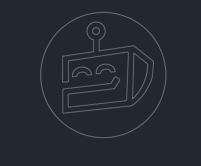
To start off, we will design the denominations of chips with branded images, featuring monetary values of $1, $10, $20, $50, and $100 (These can also double as cents, not necessarily dollars).
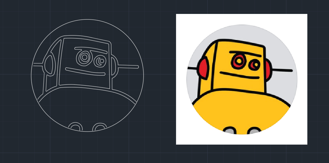
For the $1 dollar chip, I felt that a simplistic image would work best as the value of chip would be the lowest. For inspiration, I saw a simplistic drawing of the Instructables bot made by Robert Caudle (Link Here), and decided to model the chip after it. Once finding the reference image, I copied that picture into the workspace of AutoCad, where from there I would used the polyline command to trace out the outline of the robot. Polyline is great as it doubles as a means to draw arcs in addition to straight edges. The key to make a really nice and crisp image with polyline tracing is to trace both the outside and inside edge, and then trim whichever overlaps are needed to remove.
Once I had the image done, I encased it within a circle, placed it in the center of said circle, and finally scaled everything so that the outer circle had a diameter of 1.5 inches, which is the standard dimension of a poker chip.
$10 Chip
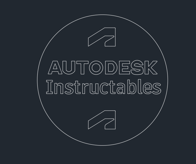
Moving on to the next value, I designed what would be the $10 chip. The reference I drew here was with the text and logo of Autodesk and Instructables, which happens to be the company which this custom set is set out for.
I again used the same polyline tracing technique as opposed to just typing the text, as I wanted to font to be the exact same as seen on the Instructables website. That was simple enough, and on the top and bottom of the text "Autodesk Instructables" I traced out an outline of the Autodesk logo itself just to fill in the space a little better.
I repeated the same scaling process as before, which I will do for every single design as well moving forward.
$20 Chip
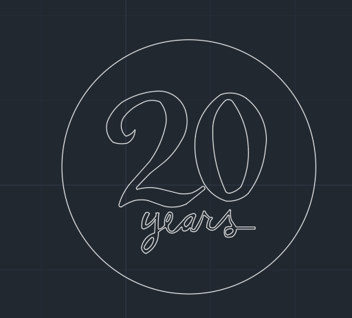
As an homage to the 20th anniversary of Instructables, I felt it would be only right to make the $20 chip a reference to that very fact, and pattern this chip with text that says "20 years" in a fun playful font. I scoured the internet for a picture that said 20 years in a font that I felt was fitting, and once I had found it, copied it into the workspace and used the same process as before.
$50 Chip
For the second to last chip, the $50 chip, I took the classic Instructables robot and traced him out accordingly. This image was no harder than any of the last, but just make sure that if you are trying to replicate the process yourself, to again trace both the inside and outside lines of the image and not one central line, as the result will be much cleaner.
I say this image works as the 50th denomination as its much more detailed than the robot present on the simple $1 chip, yet leaves an opening for something even bigger and better for the highest chip, the $100 chip.
$100 Chip
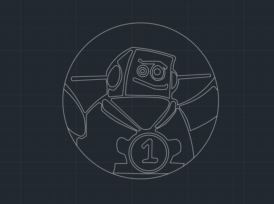
And lastly, here we have the $100 chip. This chip features the same traditional look of the Instructable robot, only this time with a medal that has #1 on it. This is a cool way to show off the highest value of chip we have in the set as the bot bears a medal with the highest of honor on it.
Arraying of Chips
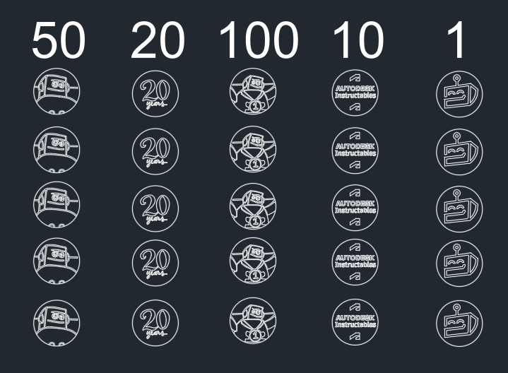
Before moving onto printing, I decided to bring all the chips together in an array to organize the values and such. I decided on a 5x5 array, giving you 25 chips in total to print on a sheet. Of course, if you'd like, you can change the dimensions of the array to whatever suits your needs.
Additionally, I just wrote some simple markings along the top of the array with the corresponding value of the chip below it, just so you have a better idea of which is which.
(Attached below is the DXF File needed to print the chips for yourself if you'd like)
Downloads
Frame of the Chip Holster
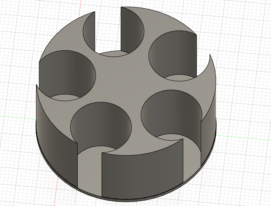
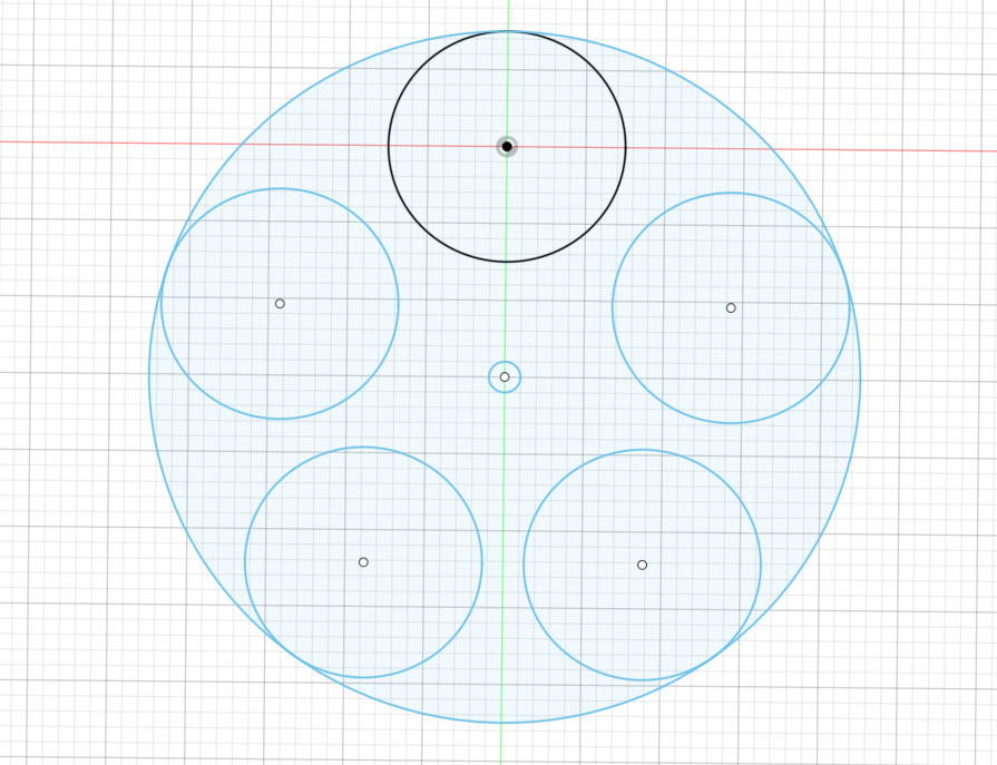
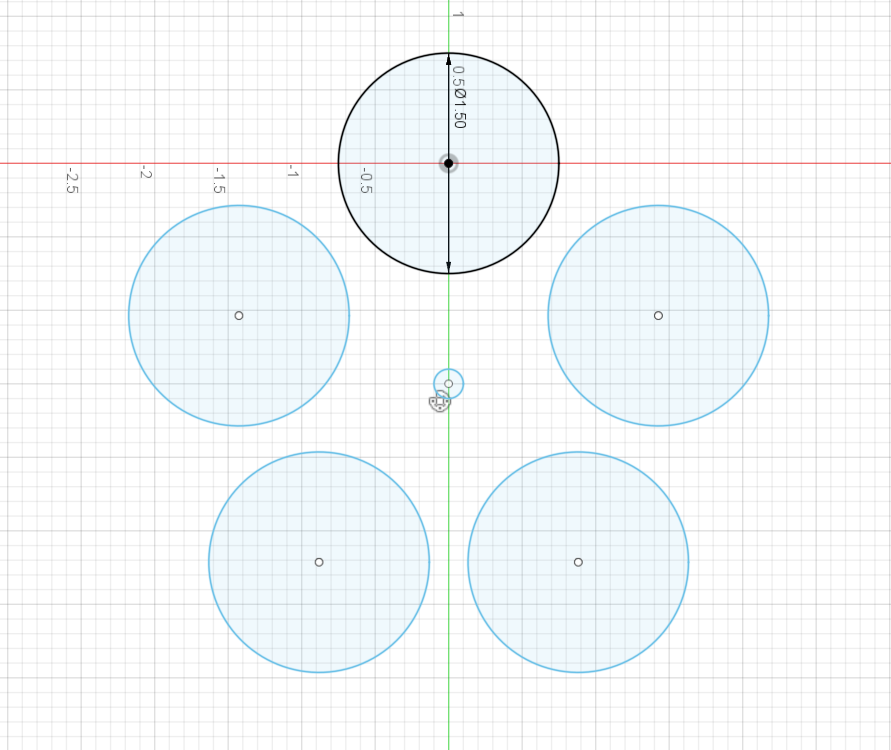
With the chips all designed, it's time to move onto making the holster to house them. In a new fusion file, start by creating a polar array of 5 circles, with diameters slightly bigger than the chips, such as seen in the third picture.
From there, make a new circle with the same center as the one you used for the array, and create an outer encasing circle that is tangent to each original circle at one point, as seen in the second image.
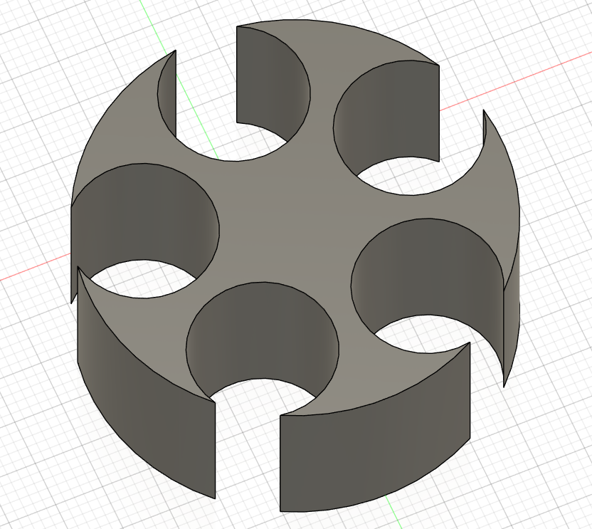
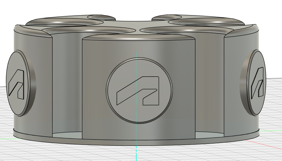
With those two steps done, you essentially can make the whole holster now. Start by extruding the shape of everything EXCEPT the original circles, which gets you a result like that of image 4. Next, extrude up the entire bottom shape, circle and all, and create a thin bottom for the holster, like seen in the first image. This is the main frame of your holster.
Now you can feel free to fillet, chamfer, or otherwise change the edges or shape of the holster as you wish, although I recommend only a small fillet on the sharp edges of our holster, which will make it better to hold when printed.
Finer Details
Lastly, I felt it would be nice to add some branded touches all amongst the outside of the holster.
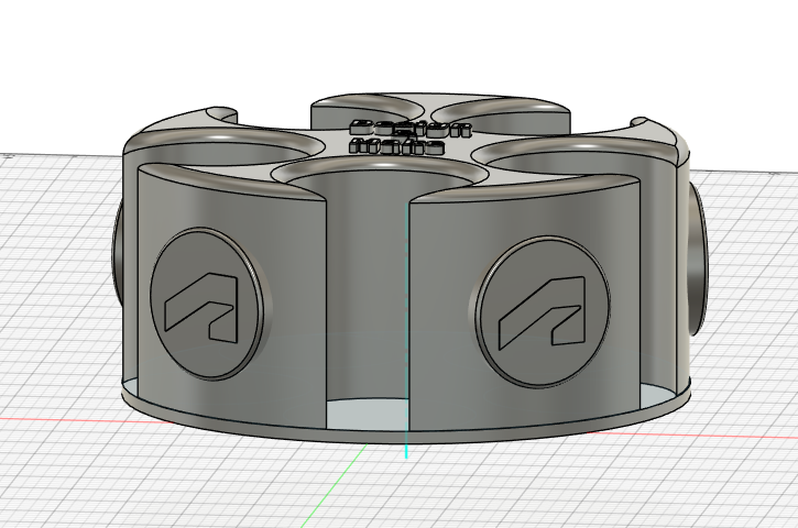
We will start by creating the extruded Autodesk logos seem amongst the outside of the contraption. By angling a work-plane 45 degrees to one of the chunks like seen in the third image, we can start by sketching out a circle in the center of said chunk utilizing the "project" tool to find the center of it. From that circle, we can extrude it out to create a little disk with a flat surface.
With this new extrusion, we can use the "canvas" command to place a picture of the Autodesk logo onto the surface. From there, we can trace out the simple shape of the logo, which then can be extruded itself to make it physical rather than a flat drawing. Once it's to your liking, use the polar array command once again to equally place this shape on every chunk, completing the symmetrical look.
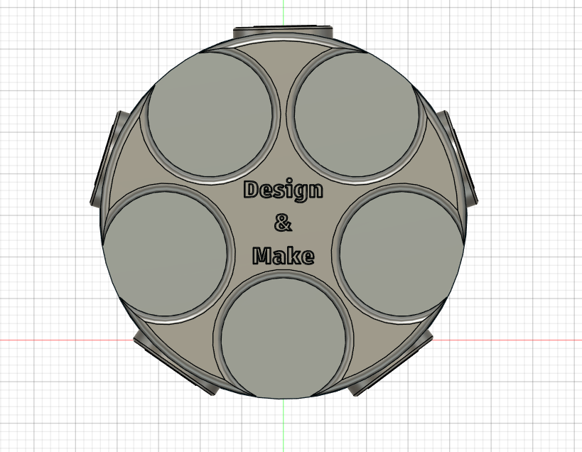
The final little touch that I decided to include were the words "Design and Make" on the top of the holster. This has sort of become the main slogan of Instructables, and felt it would be a nice way to fill in the empty space on top. First start by creating a new sketch on the flat top. From there, insert text and write out the words "Design and Make" (If you'd like you can put them all on a different line like I did). Feel free to play around with font, size and position. When it's to your liking, extrude it up by a very small amount, and filet the sharp edge to make it smooth. Congratulations, you have completed your model!
The 3D Model
The model of the holster for you to play around with (Not useable on phone)
Laser Cutting Chips
With our walls sketched out in AutoCAD, the next step is to actually cut them out. The software we will use is called Lightburn, which is typically paired with the Thunder Laser Nova 35 that we are using as provided by my schol. For more insight on how to set up your cut in Lightburn, check out this video (Click Here).
Once you’ve exported your AutoCAD file into the software however, and appropriately set it up, just start the process and wait for all your pieces to be cut. Be mindful of the thickness and dimensions of the wood you are cutting, as you might have to change things around depending on said properties.
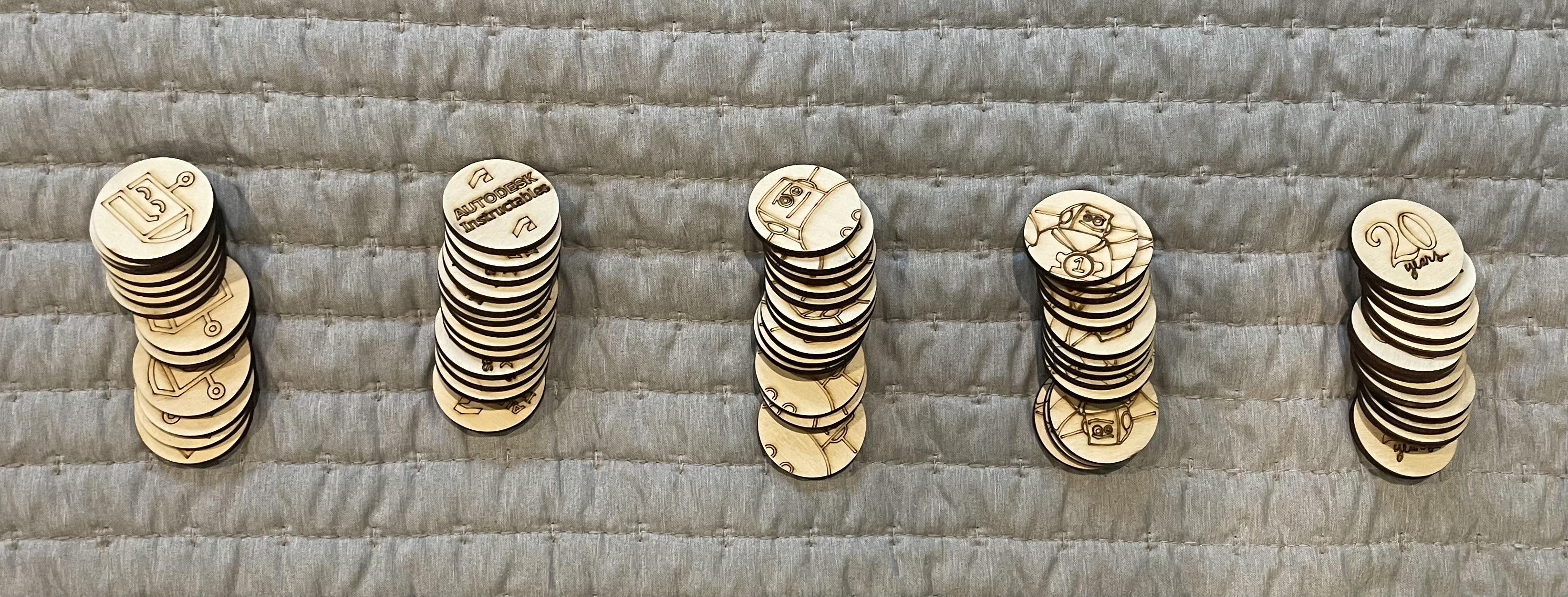
The cuts are not only extremely precise, as the laser is fine and pinpointed, but also happen rather quickly, so you can cut all of the pieces you need in a few minutes. In the end, you should have all your needed pieces cut straight and efficiently.
3D Printing Holster
The tool I will use for printing out my holster is the Bambu Lab A1 mini printer, which is the one my school provides. This printer has a respective software as well, and if you want to learn how to set up a print, you can watch this video (Click Here).
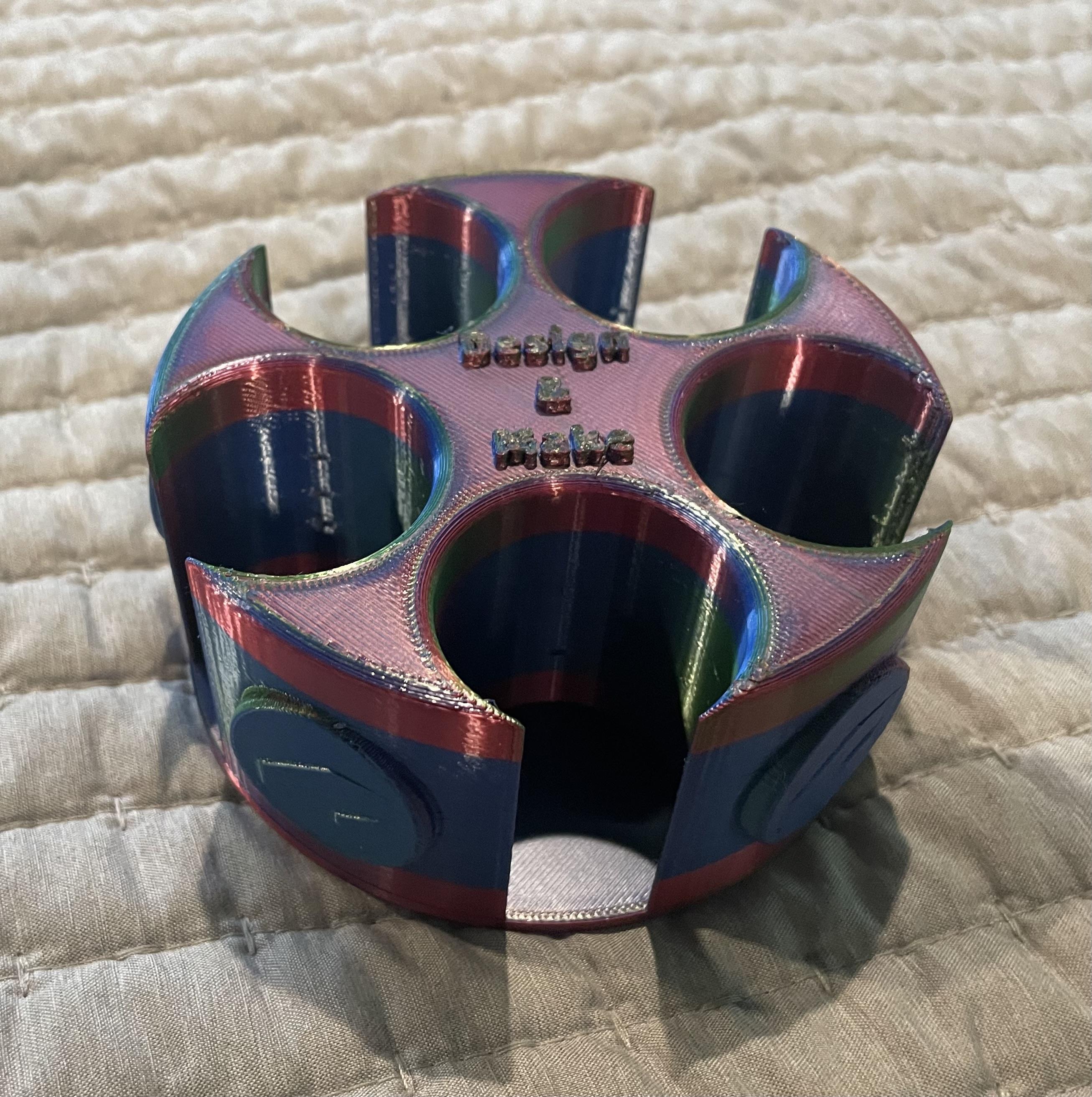
I took the exact model of the holster directly from Fusion, and in about 3 hours, had it printed out of a really cool iridescent filament.
(I attached the printing file below)
Downloads
Final Assembly

And finally, with both our chips and holster done, we can put everything today and have a really nice custom Instructables set. A little tip is to be mindful of the material you are printing/cutting with, as some materials will have more friction than others, and thus the chips might not be able to slide as easily. To remedy this, you might want to scale down the chips ever so slightly to a diameter of roughly 1.45 inches as opposed to 1.5 on the dot.
Regardless, the final product is extremely cool, functional, and pays some nice homage to some of the history and significance of the Instructables platform. Creating the designs and models, and then going a step further to bring them to life, was a really fun and gratifying process. I wish from this you learned how to bring a cool idea to life yourself, or maybe even felt the urge to create this very set yourself. All in all though, this was a fun challenge, and a hopefully an appropriate way to celebrate the 20th birthday of Instructables! Thank you all!