Cyber Gamming Console Ver 1.0 - by Nihilan S
by nihilan2106 in Circuits > Electronics
39 Views, 0 Favorites, 0 Comments
Cyber Gamming Console Ver 1.0 - by Nihilan S
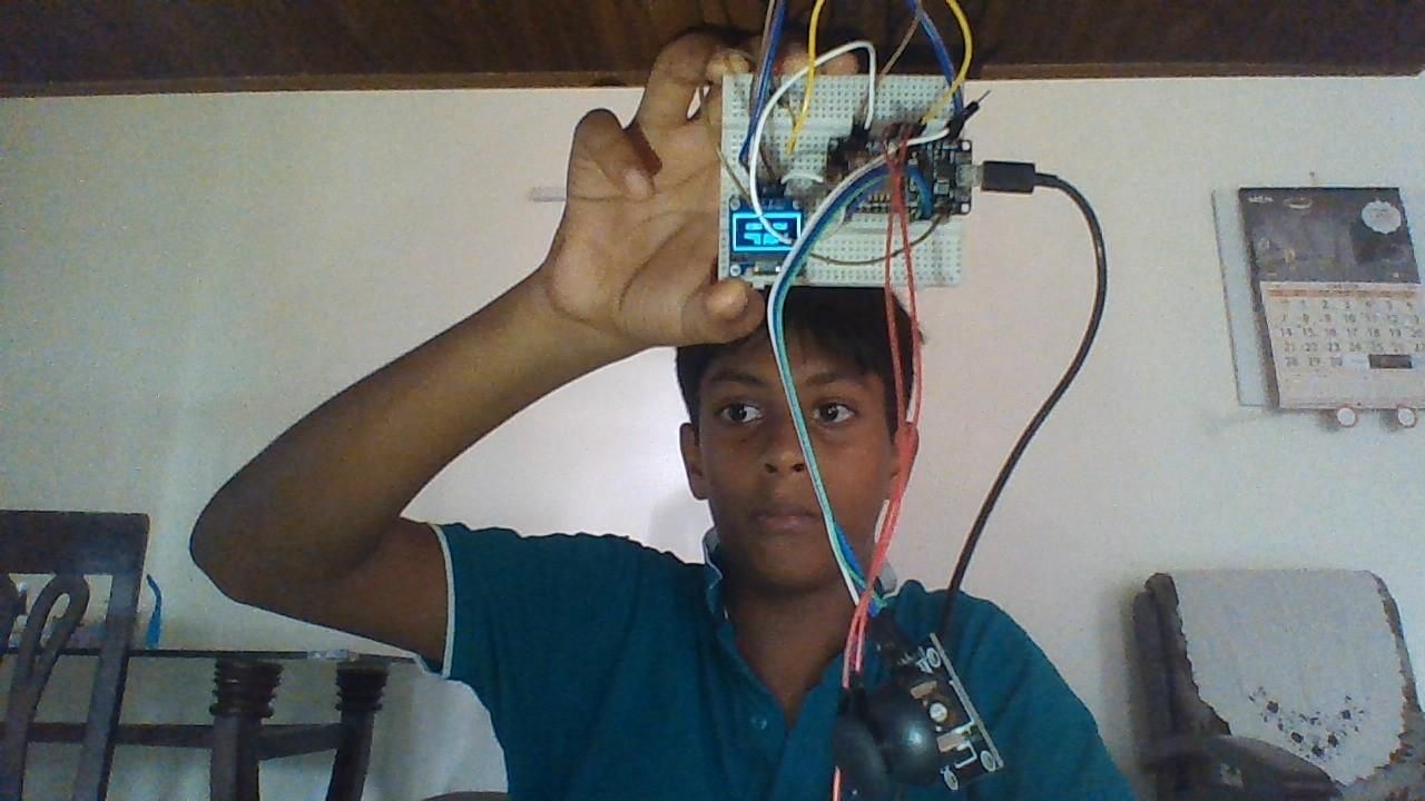
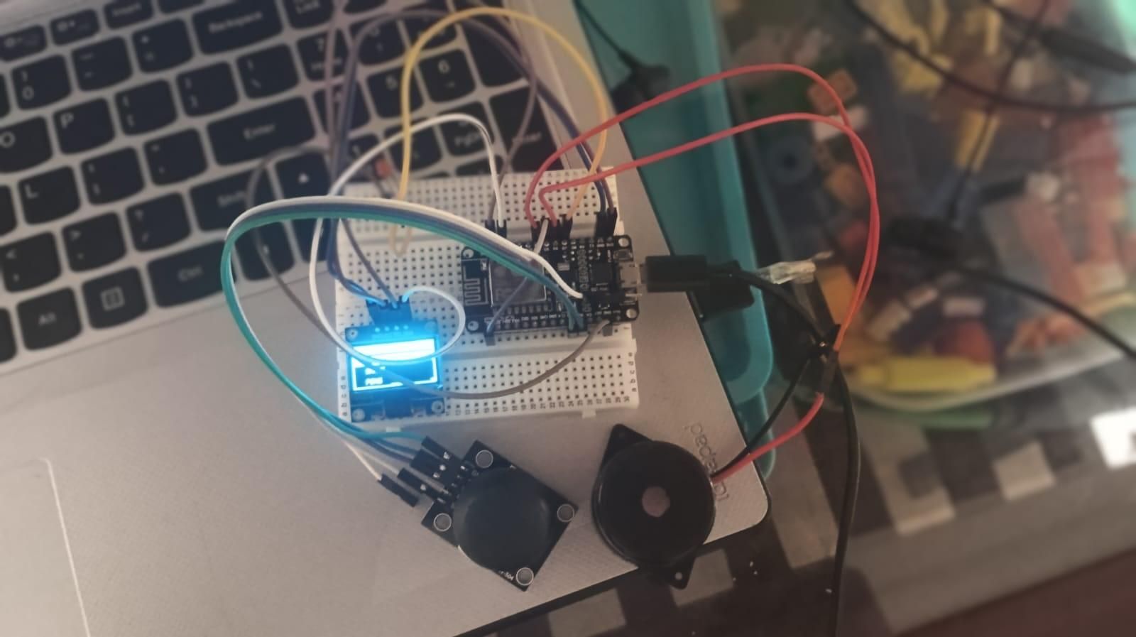
Cyber Console Overview
The Cyber Console is a compact retro-inspired handheld gaming system built using the NodeMCU ESP8266 and a 128×64 SSD1306 OLED display. It combines classic arcade games with a futuristic cyberpunk interface to create an engaging portable gaming experience.
The console is controlled using a joystick for navigation and movement, while the joystick's push button is used for actions such as selecting menu options, jumping, shooting, and restarting games. The built-in FLASH button (GPIO0) serves as a pause button and allows the player to return to the main menu with a long press. An active buzzer provides sound effects for gameplay and menu interactions, while a red LED acts as a status indicator, displaying different blink patterns during startup, gameplay, collisions, low health, and game over events.
To enhance the user experience, the console features a polished boot animation with a loading sequence, animated diagnostics, and a cyber-themed startup screen. A smooth animated menu lets users choose between five built-in games:
- 🏃 Cyber Runner
- 🐍 Snake
- 🏓 Pong
- 🎯 Dodger
- 🚀 Space Shooter
Additional sections such as Settings and About allow users to adjust difficulty, toggle sound, and view system information.
The project demonstrates how a low-cost ESP8266 can be transformed into a feature-rich handheld gaming console through efficient programming, optimized graphics, responsive controls, and thoughtful user interface design. It showcases embedded systems programming, game development, hardware integration, and user experience design in a single project.
Supplies
Materials Used
- NodeMCU ESP8266 – Main microcontroller that runs the entire gaming console.
- 0.96" SSD1306 OLED Display (128×64, I2C) – Displays the boot animation, menus, and games.
- Joystick Module – Used for menu navigation and in-game movement, with its push button for actions like jump, shoot, and select.
- Active Buzzer – Produces sound effects for the menu, gameplay, and startup.
- 5 mm Red LED – Provides visual status indications such as booting, warnings, and game events.
- 220 Ω Resistor – Limits current to protect the red LED.
- Breadboard or Custom PCB – Holds and connects all the components.
- Jumper Wires – Used to make electrical connections between components.
- Micro USB Cable – Powers and programs the NodeMCU.
Software Used
- Arduino IDE – Used to write, compile, and upload the code.
- ESP8266 Board Package – Enables programming the NodeMCU within the Arduino IDE.
- Adafruit GFX Library – Provides graphics functions for drawing text and shapes.
- Adafruit SSD1306 Library – Controls the OLED display.
- Wire Library – Handles I²C communication between the ESP8266 and OLED display.
Tools Used
- Soldering Iron (if assembling on a PCB)
- Solder Wire
- Wire Cutter/Stripper
- Small Screwdriver (optional)
- Computer or Laptop for programming
- USB Cable for uploading the code and powering the console
Gather the Components
Electronics
- 1 × NodeMCU ESP8266
- 1 × SSD1306 OLED Display (128×64, I2C)
- 1 × Joystick Module
- 1 × Active Buzzer
- 1 × 5 mm Red LED
- 1 × 220 Ω Resistor
- Jumper Wires
- Breadboard or Custom PCB
- Micro USB Cable
Software
- Arduino IDE
- ESP8266 Board Package
- Adafruit GFX Library
- Adafruit SSD1306 Library
Install the Arduino IDE
Download and install the Arduino IDE.
Open the Arduino IDE.
Go to File → Preferences.
In Additional Boards Manager URLs, add the ESP8266 package URL.
Open Boards Manager.
Install ESP8266 by ESP8266 Community.
Install the Required Libraries
Open
Sketch → Include Library → Manage Libraries
Install:
- Adafruit GFX
- Adafruit SSD1306
The Wire library is already included with Arduino IDE.
Assemble the Circuit
connect the OLED display.
OLED to NodeMCU
VCC
3.3V
GND
GND
SDA
D2
SCL
D1
Connect the joystick.
Joystick to NodeMCU
VCC
3.3V
GND
GND
VRX
A0
SW
D5
Connect the active buzzer.
Buzzer to NodeMCU
+
D6
–
GND
Connect the LED.
LED Positive
↓
220 Ω resistor
↓
NodeMCU D7
LED Negative
↓
GND
Connect the NodeMCU
Connect the NodeMCU to your computer using a Micro-USB cable.
The power LED should turn on.
Configure the Arduino IDE
elect:
Board
NodeMCU 1.0 (ESP-12E Module)
Select the correct COM Port.
Leave the remaining settings at their defaults unless you have a specific reason to change them.
Upload the Program
- Open the Cyber Console sketch.
- Click Verify to compile it.
- Click Upload.
- Wait for the upload to finish.
Do not hold the FLASH button during upload unless the IDE specifically requires it.
First Start Up
After programming:
The console will display:
- Cyber boot animation
- Loading bar
- System diagnostics
- Cyber Console logo
The red LED will blink according to the startup sequence.
The buzzer will play startup sounds.
Navigate the Menu
Use the joystick:
- Move Left → Previous menu item
- Move Right → Next menu item
Press the joystick button to select a game.
Long press the FLASH button to return to the main menu or pause the current game, depending on your software design.
Play the Games
The console includes:
- Cyber Runner
- Snake
- Pong
- Dodger
- Space Shooter
Each game has its own controls, score system, and game-over screen.
Sound and LED Feedback
The active buzzer provides feedback for:
- Startup
- Menu navigation
- Game events
- Collisions
- Game over
- Victory
The red LED indicates different system states, such as:
- Booting
- Menu
- Gameplay events
- Warnings
- Victory
- Game over
Troubleshooting
OLED is blank
- Check SDA and SCL wiring.
- Confirm the display uses I²C.
- Verify the display address (commonly 0x3C).
Joystick does not respond
- Check the VRX connection to A0.
- Verify the SW connection to D5.
- Ensure the joystick is powered from 3.3V.
Buzzer does not sound
- Confirm it is an active buzzer.
- Check polarity and the D6 connection.
LED does not light
- Verify the LED polarity.
- Ensure a 220 Ω resistor is used.
- Check the D7 connection.
Upload fails
- Confirm the correct board and COM port are selected.
- Avoid holding the FLASH button unless needed for programming.
Customization
Once everything is working, you can personalize your console by:
- Designing a custom 3D-printed or laser-cut enclosure.
- Painting or vinyl-wrapping the case with a cyberpunk theme.
- Adding custom boot logos and animations.
- Creating new games or expanding the menu.
- Improving graphics and sound effects.
- Using a rechargeable battery pack for portability.