DESHBOT Project – LDR Detection System With 16×2 LCD
by devkrishnavhora in Circuits > Arduino
8 Views, 0 Favorites, 0 Comments
DESHBOT Project – LDR Detection System With 16×2 LCD
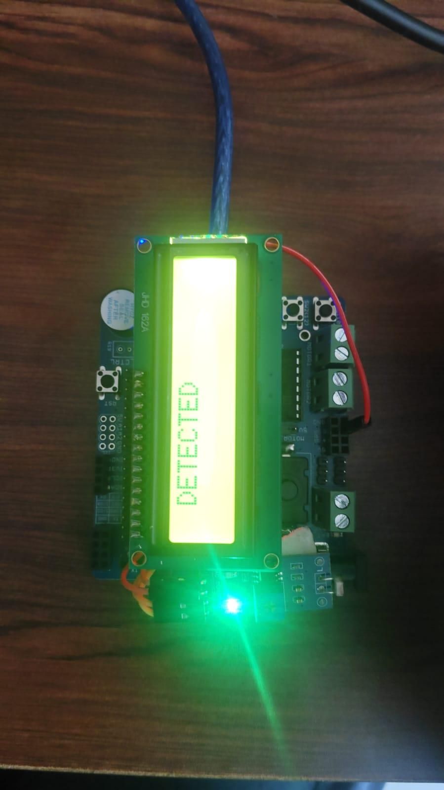
The DESHBOT project uses an Arduino Nano, DESHBOT Shield, 16×2 LCD, and an LDR (Light Dependent Resistor) sensor to detect light conditions and display the status.
Supplies
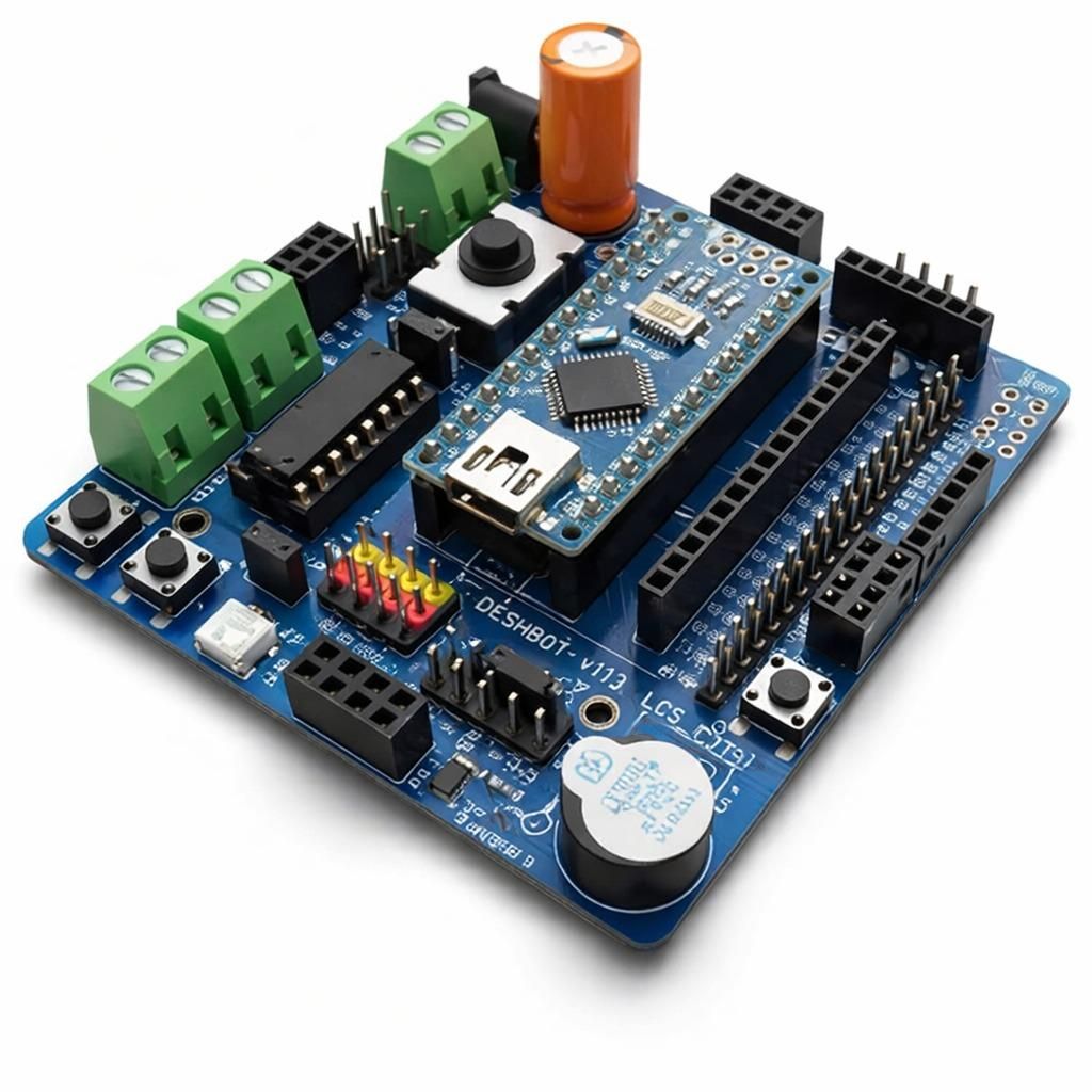
Arduino Nano
DESHBOT Shield
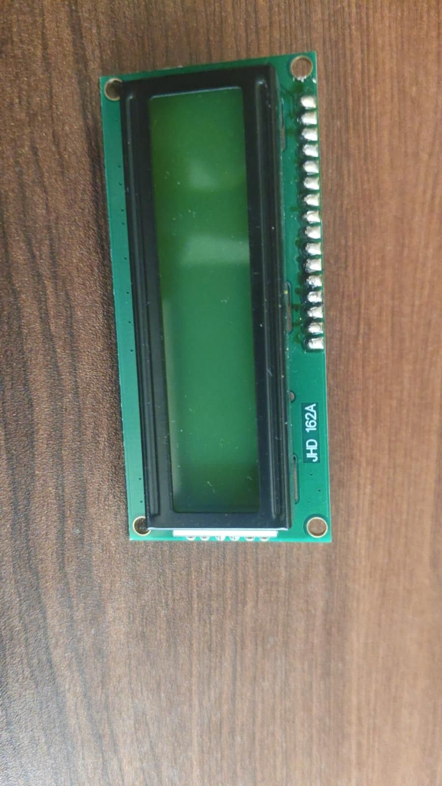
16×2 LCD Display
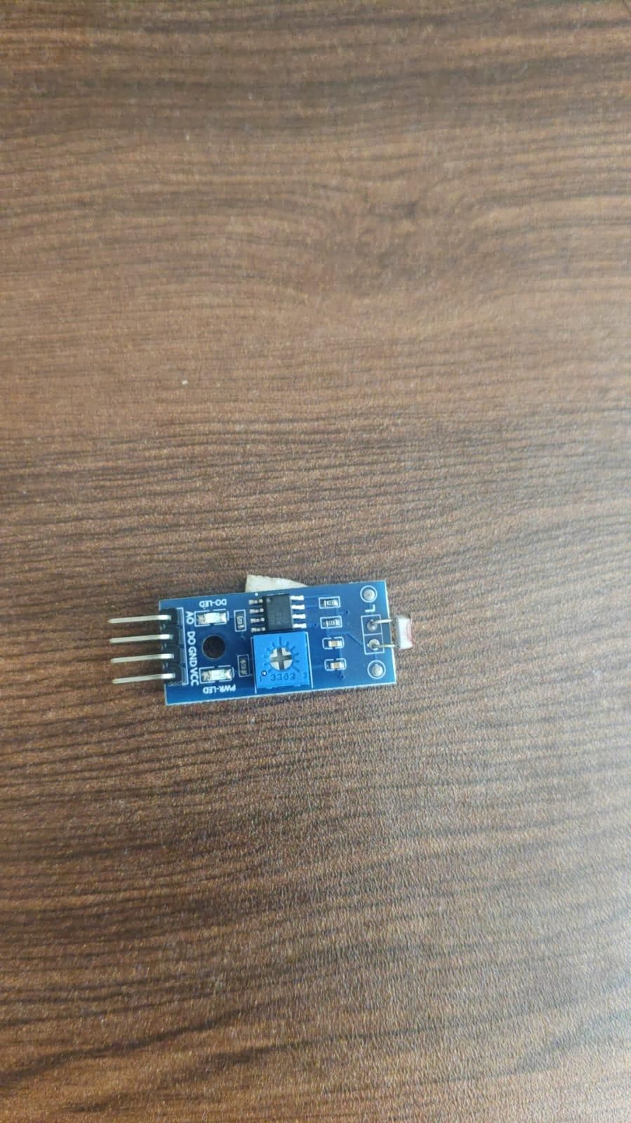
LDR Light Sensor Module
Jumper wires
USB cable
Working Principle
The DESHBOT project uses an Arduino Nano with an LDR light sensor and a 16×2 LCD display to detect light conditions. The LDR continuously checks the surrounding light, and the LCD displays whether LIGHT IS DETECTED or LIGHT IS NOT DETECTED.
Connect the 16×2 LCD
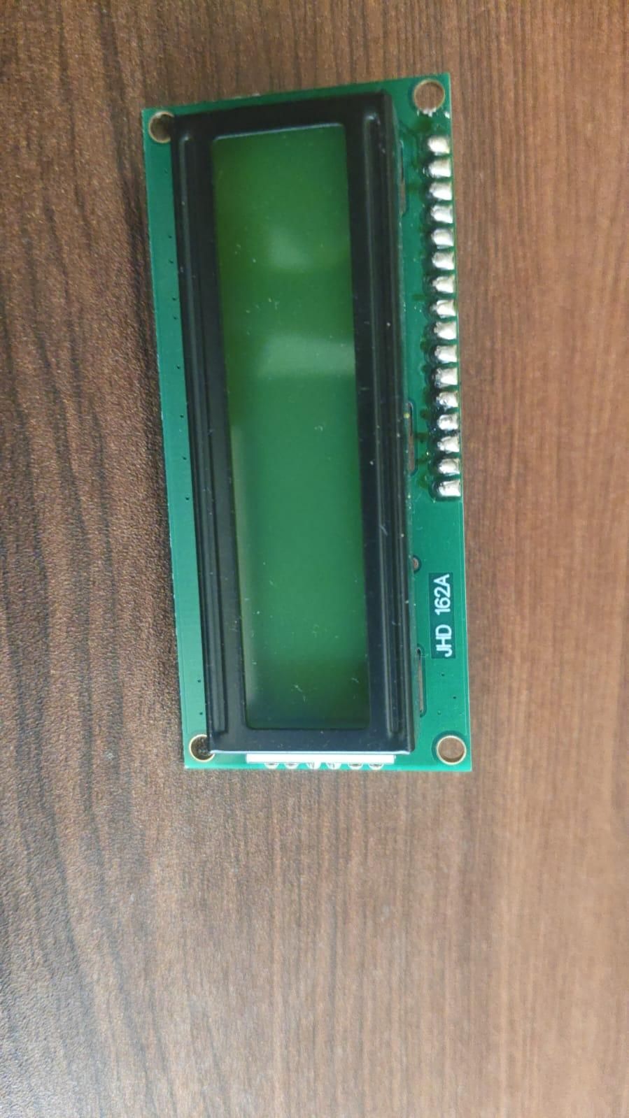
Connect the 16×2 LCD to the Arduino Nano using the DESHBOT connections.
The LCD is used to display the current light detection status. After connecting the LCD, check that it is properly powered and that the display text is visible.
The LCD will show messages such as:
or:
Connect the LDR Sensor
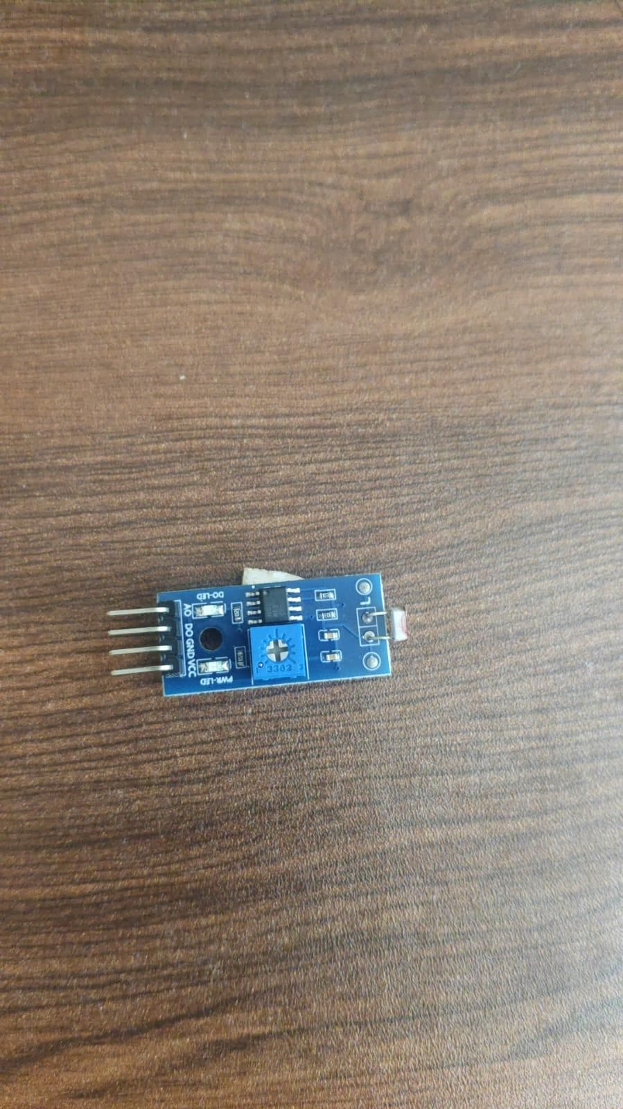
Connect the LDR sensor module to the Arduino Nano.
The LDR module normally has the following pins:
- VCC → Arduino 5V
- GND → Arduino GND
- D0 → Arduino Digital Input Pin
- A0 → Arduino Analog Input Pin if analog reading is required
For this project, the LDR output is continuously read by the Arduino Nano to determine whether light is detected.
Set the LDR Detection Condition
The LDR sensor detects changes in the amount of light.
Depending on the module setting:
- When sufficient light is detected, the Arduino reads the LIGHT DETECTED condition.
- When the LDR is covered or the light level changes below the selected threshold, the Arduino reads the LIGHT NOT DETECTED condition.
The detection threshold can be adjusted using the potentiometer on the LDR sensor module.
Upload the Arduino Sketch
Open the DESHBOT Arduino Nano sketch in the Arduino IDE.
The sketch should initialize:
- The 16×2 LCD display
- The LDR sensor input
- The light detection condition
The Arduino continuously reads the LDR sensor and updates the LCD according to the sensor status.
Downloads
Light Detected
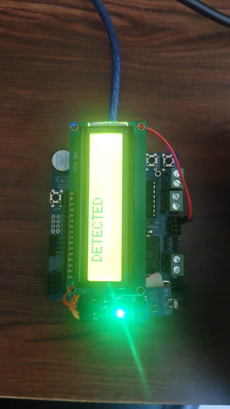
When the LDR sensor detects light, the LCD displays:
This indicates that the LDR is receiving light and the sensor has detected the required light condition.
Light Not Detected
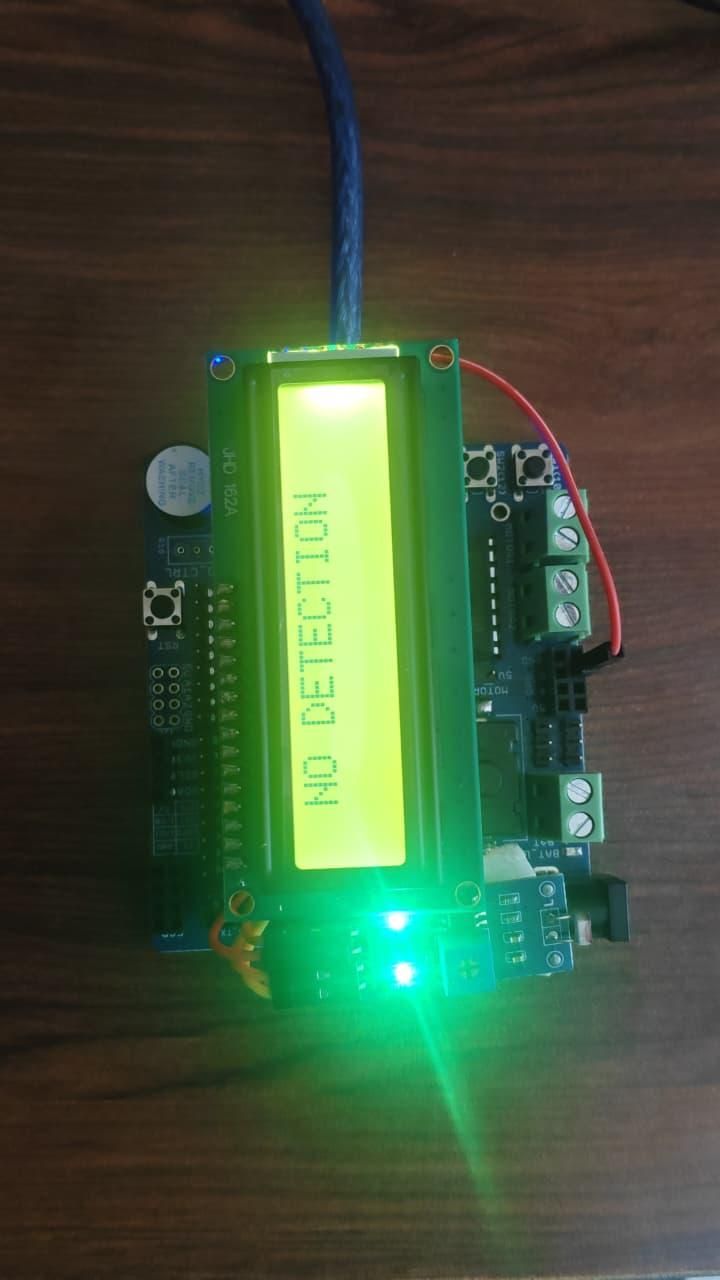
When the LDR sensor is covered or does not detect sufficient light, the LCD displays:
This indicates that the light level has changed and the selected detection condition is no longer active.
Test the Project
Upload the completed DESHBOT sketch to the Arduino Nano.
After uploading:
- Power ON the DESHBOT system.
- Check that the 16×2 LCD is working correctly.
- Allow light to fall on the LDR sensor.
- The LCD should display LIGHT DETECTED.
- Cover the LDR sensor with your hand.
- The LCD should change to LIGHT NOT DETECTED.
- Remove your hand and allow light to reach the sensor again.
- The LCD should return to the LIGHT DETECTED status.
Working Principle
The LDR changes its output according to the amount of light falling on the sensor. The Arduino Nano continuously monitors this output and compares it with the selected detection condition.
When the light condition matches the selected setting, the LCD displays LIGHT DETECTED. When the light condition changes, the LCD displays LIGHT NOT DETECTED.
This process repeats continuously, allowing the DESHBOT system to monitor the light status in real time.
Important Note
The LDR sensor module may work with either HIGH or LOW output logic, depending on its configuration. Before finalizing the Arduino code, test the LDR by checking its output when exposed to light and when covered.
If the LCD displays the opposite status, reverse the detection condition in the Arduino sketch so that LIGHT DETECTED and LIGHT NOT DETECTED match the actual LDR sensor behavior.