DIY 3D Navigator for Blender


A DIY 3D navigator for Blender, inspired by KikiHobbyRepair's SpaceRat (link here).
It uses an MPU6050 3-Axis Accelerometer mounted on a steel spring and a rotary encoder. 8 MX keys and 2 push buttons provide command customization options. Each button can be assigned single and double click commands, as well as hold actions (check attached image). A HID capable board is necessary to convert the key strokes into keyboard commands (such as Teensy 2).
To orbit, simply move the knob while the cursor is on the 3D View (this emulates the movement while the MMB is pressed).
To pan, press and hold the knob while moving (this is the equivalent of holding Shift + MMB).
I recommend setting the "Orbit Around Selection" option in Preferences > Navigation > Orbit and Pan.
Optional
The Neopixels flash the Blender colors at startup, and then randomly pick one. The lights can be cycled by double-clicking on the left button (blue > orange > white > off).
Supplies
- 1 HID compatible controller (I used a Teensy 2)
- 1 MPU6050 3-Axis Accelerometer
- 1 EC11 rotary encoder (20mm shaft)
- 2 Momentary Push Buttons (6mm x 6mm x 7mm)
- 1 Mini USB Type B male connector
- 1 female USB C board
- 1 set of male-female Micro JST connectors
- 1 Steel spring (8mm diameter/20mm long): I used one from a 3D printed bed.
- 10 Steel washers (8mm x 24mm)
- 8 MX keyboard switches
- 15 M3 brass inserts (M3x4x5mm)
- Assorted M3 flat head screws: 8mm (8), 12mm (5), 2mm (2).
- Prototyping perfboard or single-/double-sided copper plates (for CNC)
- Through Hole, Right Angle Headers, Male Pin
- Thin wires for internal connections (I used an old ribbon cable I has lying around)
- Shrink tubing.
RGB Lights (optional)
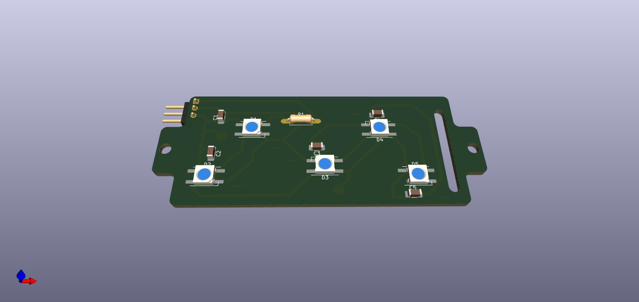
- 8 x WS2812B RGB LED 5050 with Integrated Driver Chip (Adafruit's Neopixels)
- 8 x 100nF Capacitors (I used SMDs)
- 2 Resistors (between 300 to 500 Ohm)
3D Printing and Part Preparation


The parts are all printed in PLA (The .blend file can be found here).
Most parts can be printed in any filament color and without supports, except for:
- 01-Body.stl: with supports
- 11-MPU6050_Mount: with supports
- 12-Rotary_Encoder_Mount.stl: with supports
04-Key holder.stl and 06-LED_ring_cover.stl must be printed in white/transparent filament, with supports. This is to allow the light from the LEDs to pass through.
*05-Keypad_LED_holder.stl can be used instead of a perfboard.
There are two versions of the bottom lid: A normal one (02a-Bottom_Lid_NO_WEIGHTS.stl), and one with spaces for washers to add weight while printing (02b-Bottom_Lid_WITH_WEIGHTS.stl). This model is designed to insert the washers during the print. I used Cura's Pause at Height plugin to insert the steel washers.
Once printed, the M3 brass inserts can be placed on the parts using the tip of a soldering iron, taking care not to insert them too deep:
- Body: 5 inserts to hold the lid screws, and 2 more to hold the key/boards assembly in place.
- Central spring bottom: 3 inserts.
- Central spring top: 3 inserts to hold the rotary encoder and 2 inserts to hold the MPU6050 (although here 1 might be enough).
The spring bottom and top parts are glued to the spring using epoxy. It is important to make sure the center hole of the spring is kept clear of the glue, since that space is used to insert the wires that connect to the MPU6050 and the rotary encoder at the top of the knob. I inserted a piece of shrink tubing into the spring hole while the epoxy was soft, and removed it as soon as it started setting.
It is also important to keep in mind the orientation of the holes on the body to make sure the sensor end up pointing forward.
Downloads
Electronics


Although I made the boards for this project using a CNC, it can also be made with perfboard or simply printing the supports in PLA. The kikad files for all the boards can be found here.
The main board holds the Teensy and the pin headers for the sensor, buttons and the LED boards (for the keys and the ring around the base of the knob, see next step).
The first version contemplated using the Teensy's reset pin, but that was later changed to use Pin 3 to add an extra button.
I attached a male mini USB connector to four wires ending in a male JST connector. The female JST connector was attached to the USB-C board placed on the bottom lid.
Then I soldered wires to the push buttons, ending in female pin connectors.
RGB LEDs (optional)


Keeping in mind the space limitation, I decided to add WS2812B RGB 5050 LEDs, which are quite straight forward to use with Adafruit's Neopixel library.
The keys section has 5 pixels, while the ring only uses 3. As recommended by Adafruit, the data pin connecting to the Arduino is connected to a resistor (between 300 to 500 Ohm). Also, 100 µF capacitors where installed next to each pixel to improve reliability. I know this might be overkill for such a small project, but it was good soldering practice :)
Each LED board is driven by one Teensy pin.
Putting It All Together


.jpg)


I installed the LED ring board in the body, then placed the LED ring cover on top. No glue was necessary since the tolerances of the print were quite right (here your mileage might vary depending on your printer and print settings).
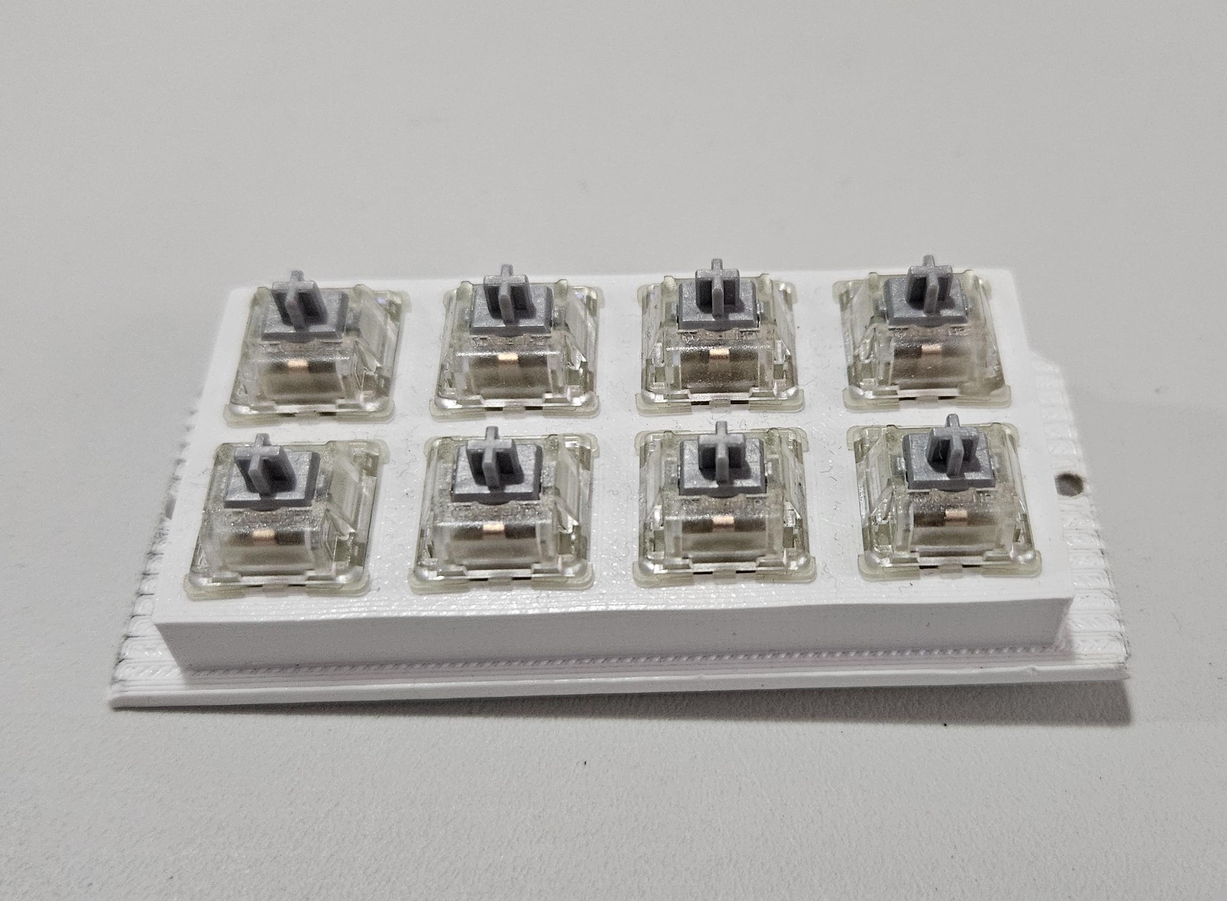
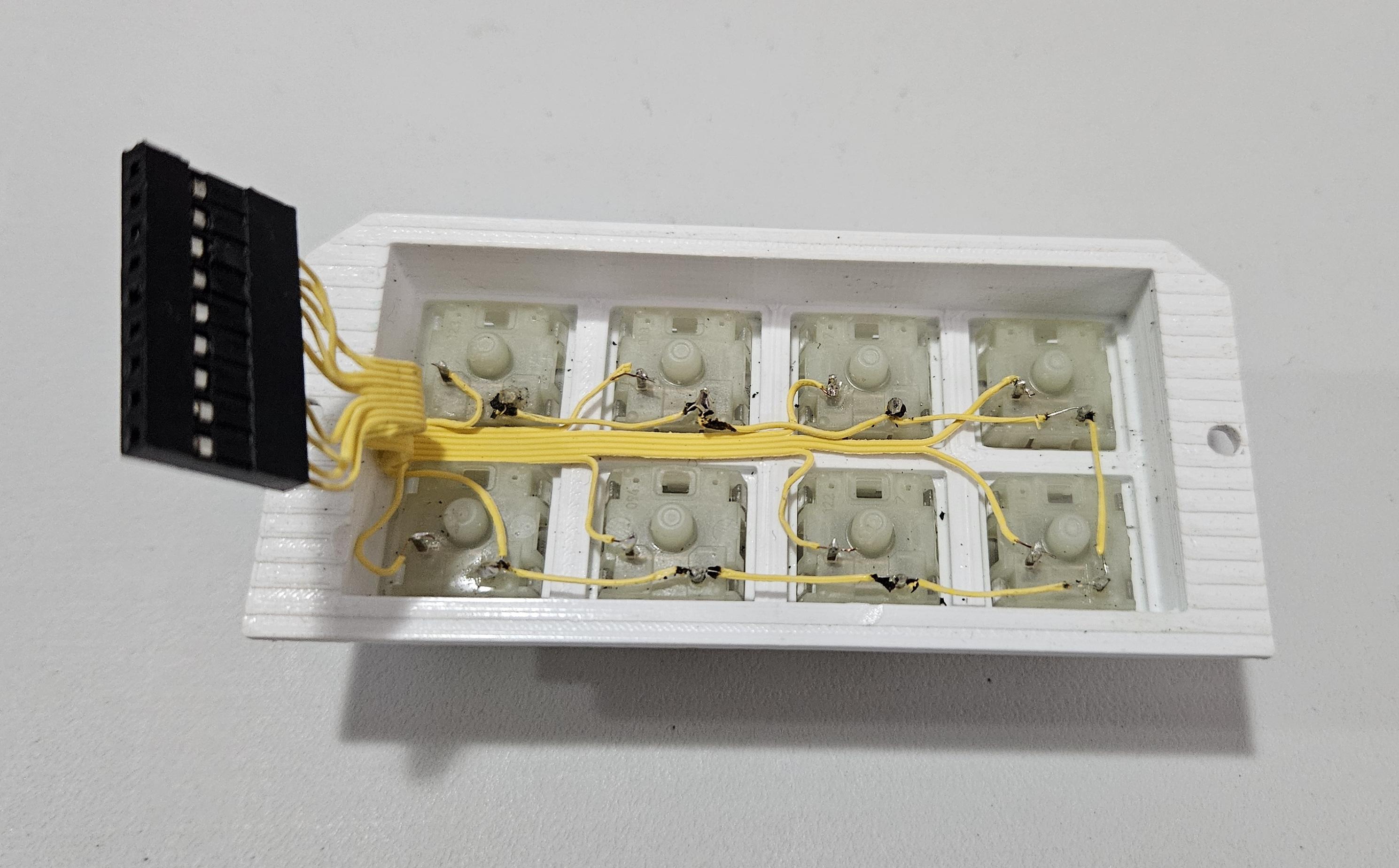
The MX keys were press fitted on the key holder (again, no glue necessary. Then I proceed to solder the wires keeping in mind the orientation of the slit to pass the wires through the LED board and the Main board. I used an old PC ribbon cable, ending in a pin socked connector (9 in total: 1 for each key and 1 for GND).
Once the boards are in place, with the ribbon cable inserted through both of them, you can connect the LED and key cables to the main board. Now it's time to fix the assembly to the body using 2 12 mm M3 screws. The one next to the key pin socket can be a bit hard to insert. It might be necessary to slightly bend up the pin headers and the bend it back once the screw is in place.
Next, the push buttons and their wires are inserted from the top, then glued in place. Their wires are then connected to their respective pins on the main board. The printed button caps are then fitted onto the switches.
The ring LED is connected to the board with 3 wires and their respective 3-pin socket connectors.
The USB extension cable is connected to the Teensy.
The spring assembly is then installed inserting 3 M3 screws (8mm) from the bottom of the body.
Another ribbon cable is used to connect the board to the sensor and the rotary encoder. It has to be a very thin wire so that it’s able to pass it through the central hole of the spring assembly, its end connecting to the board is fitted with a pin socket connector.
The SDA, SCL, +5V and GND wires are soldered to the MPU6050. Then the sensor is held on the base with 1 or 2 2mm M3 screws. The wires of the rotary encoder are also soldered at this point (GND and Signal for the button, and GND and é signal pins for the rotary encoder).
The rotary encoder is installed on its support using its washer and nut, and then it is fixed on top of the MPU6050 with 3 M3 screws. The knob can be pressed on the rotary encoder shaft.
Finally, inserting the USB-C board into the lid and connecting the the USB extension to it, the lid can be installed with 5 8mm M3 screws. Although there is enough space for the wires, it's important to make sure no wires are pressed or bent by the lid (if you look closely at the image, you will see that I damaged the cable. Be careful when closing the lid!!!).
It's done!!!
Now to programming!!
Programming (Arduino)

The 3D navigator is designed to be used with a Teensy 2 (with the Arduino IDE and the Teensyduino software add-on) using the Teensy keyboard library and its key codes (https://www.pjrc.com/teensy/td_keyboard.html). It can be adapted to work with Arduino boards with built-in HID support, such as the Arduino Leonardo and the Arduino MICRO using a ATMega32u4 MCU, but I suppose it must use the Arduino key codes (they're slightly different).
The MPU6050 section is based on the excellent 3D SpaceRat by KikiHobbyRepair, using the MPU6050_light library by rfetick.
The buttons interface was adapted from the OneButton library by Matthias Hertel. This library allows to easily assign single and double-click actions, as well as long-press (hold) commands. The image shows the key bindings I chose based on the most commonly used keys for my Blender workflow.
The RotaryEncoder library, also by Matthias Hertel.
The neopixel section was adapted from Adafruit's Neopixel sketch.
To Do & Model 2
TO DO
My coding skills are mediocre at best, so I suppose this code can be greatly improved/optimized.
Other functionalities can be added:
- Different key bindings to use with other software. Maybe each color can represent a different key binding scheme for different apps.
- A smoother scrolling movement (see below).
Gyro prototype
I designed a prototype using the MPU6050's gyroscope for scrolling rather than the rotary encoder.
It uses a bearing to spin the knob, as well as a TPU spring to return it to the center. In the end I wasn't happy with the design and decided to stick to the rotary encoder model. The "DIY_3D_navigator_gyro_prototype.ino" file contains the necessary code to implement the mouse movement with the accelerometer and scrolling with the gyroscope (but not much else). The .blend file can be found here.
Feel free to improve on it!
Downloads
Conclusion
This was an amazing project. I had a lot of fun solving the myriad issues and difficulties that came up at every corner.
I'm really pleased with the result, but I'm already thinking about a bunch or changes and improvements. But the project had to end at some point!!
Hope you enjoyed this project as much as I did!!
Keep on making!