DIY Accurate GPS Clock

📡 GPS CLOCK 📡
Sometimes you need precision when it comes to time, but what's the best way to acquire it? Luckily mitxela provided an ingenious solution that never crossed my mind. GPS. When I first saw his video, I was intrigued by the simplicity and accuracy that it provided.
Thinking I could use a challenge, I decided to make my own version completely from scratch.
Supplies
.jpeg)


This project is not resource-demanding. To pull it off, you only need a couple of components and tools.
Components:
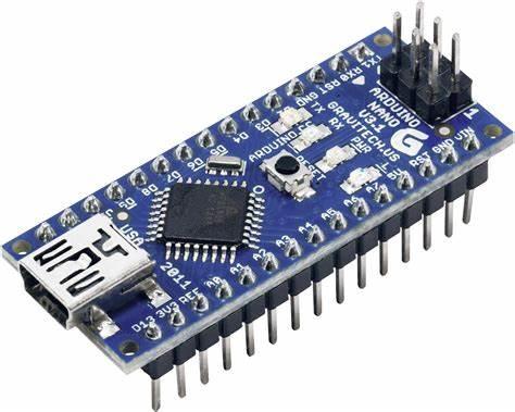
- Arduino Nano x1
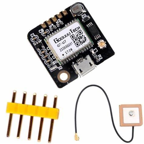
- NEO-6M (or equivalent) GPS Module x1
- MAX7219 Dot Matrix display array (At least 8 modules)
Tools:
- Solder
- Soldering Iron
- Computer
- USB programming cable
🔨 Constructing the Device 🔨


Depending on the state of your MAX7219 matrix modules, you may need to solder them together. The ones I used came with a set of 4 modules all on one board, so 8 modules total. This meant that all I needed to do was solder the two larger modules together.
If you don't have the same display as me, you may find plenty of online tutorials that will help you combine at least 8 modules. If you don't use at least 8, the text will not properly fit on the display.
You can follow the second schematic attached to this step to construct your device. I will also provide some actual pictures of my setup so that you can see exactly how I constructed it.
The first image is of only the MAX7219 Dot Matrix display, while the second is for the complete design.
⏰ Identifying Your Time Offset ⏰
.jpeg)
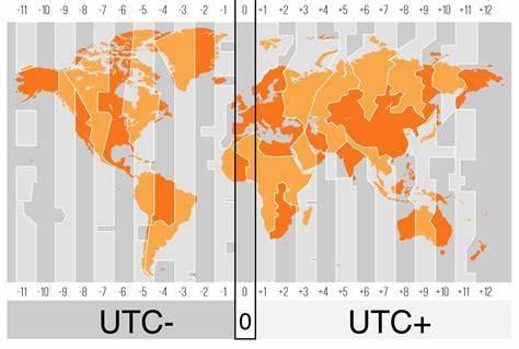
Not everyone lives in the same place. This means that not everyone has the same local time, or time offset. Because I live on the Northern East coast of the US, my offset is UTC-4 (UTC-5 from Nov.-Feb.) This UTC offset is in hours, so in my case, I am -4 hours.
The Arduino code for this project accepts your UTC in seconds, so you will need to convert whatever offset you are from hours to seconds. In my case, -4 hours corresponds to -14400 because there are 14400 seconds in 4 hours.
Once you have that, you will need to enter the value into a variable in the Arduino code, which I will explain in the next step.
👨💻 Programming the Device 👨💻

.jpeg)
Now before we get into copying and pasting code, there are a couple of important variables that need to be adjusted before the compiling and uploading process.
Things to note:
- The UTC offset time will be different for you depending on where you live. If you do not adjust this, you will end up getting the local time for where I live. You can identify your offset quite easily by reading the step above.
- There is a variable in the Arduino code that determines how many display modules are connected. By default, I have it set to 8. You may need to change this depending on your setup.
Now that we have that out of the way, you can find and copy the code from GitHub here.
Don't forget to change the variables we just talked about above!!
Now, just open up Arduino IDE, open up a new sketch with CTRL+N hotkey, or the new file button at the top left corner of the window.
Paste the code into the window, and select your board and port. In this case, we use the Arduino Nano, but this will work with just about any Arduino available.
Use CTRL+U or the upload button to compile and upload the code to your board. If there are no errors, and you see "Upload Successful" then you are done here! If not, check out the troubleshooting steps found below.
⚡ Enjoy Precision! ⚡


Now that you've got the physical device and the software uploaded to the microcontroller, assuming everything was done correctly, you will have an operational satellite clock with millisecond precision!
If you built this project, I'd love to see! Be sure to share yours down below.
If you liked this instructable, feel free to share it with a friend and heart it if you're feeling super generous! ❤😍
🤬 Troubleshooting 🤬
.jpeg)
No project seems to work on the first try, and when the scarce occasion appears, there's usually something wrong. So don't worry! This is totally normal, and trust me, I go through this section on pretty much every Instructable I follow too!
We will cover some common mistakes that even caught me off guard while constructing this myself!
Interrupt Pin:
If you are following along with this project, and you are using an Arduino or similar (with ATmega328p or similar) you should double-check your interrupt pin. The Arduino Nano supports interrupts on pins 2 and 3 only. This mistake took me a couple of days to detect, so keep that in mind!
GPS Positioning:
If you are using the NEO-6m (or similar knock-off) then you may be experiencing a lack of reception. The cheaper modules, especially the knock-off ones, tend to have less than ideal reception indoors. The onboard LED on the GPS module should be flashing 1 time per second if it has adequate satellite reception, and if not, you should try moving it around your house or closer to a window until you see it flashing.
GPS Not Working:
If you are using your GPS module for the first time, you may need to let it charge the onboard coin cell battery before it works properly. Try leaving it plugged in near a window for 24 hours and see if the onboard LED starts flashing at 1 Hz.
Something Else?
Something else seem to be the issue? Leave a comment and I'll get back to you with help as soon as I can! 😁