DIY Breath Analyzer With the MQ3
by Donut Studio in Circuits > Sensors
1682 Views, 26 Favorites, 0 Comments
DIY Breath Analyzer With the MQ3
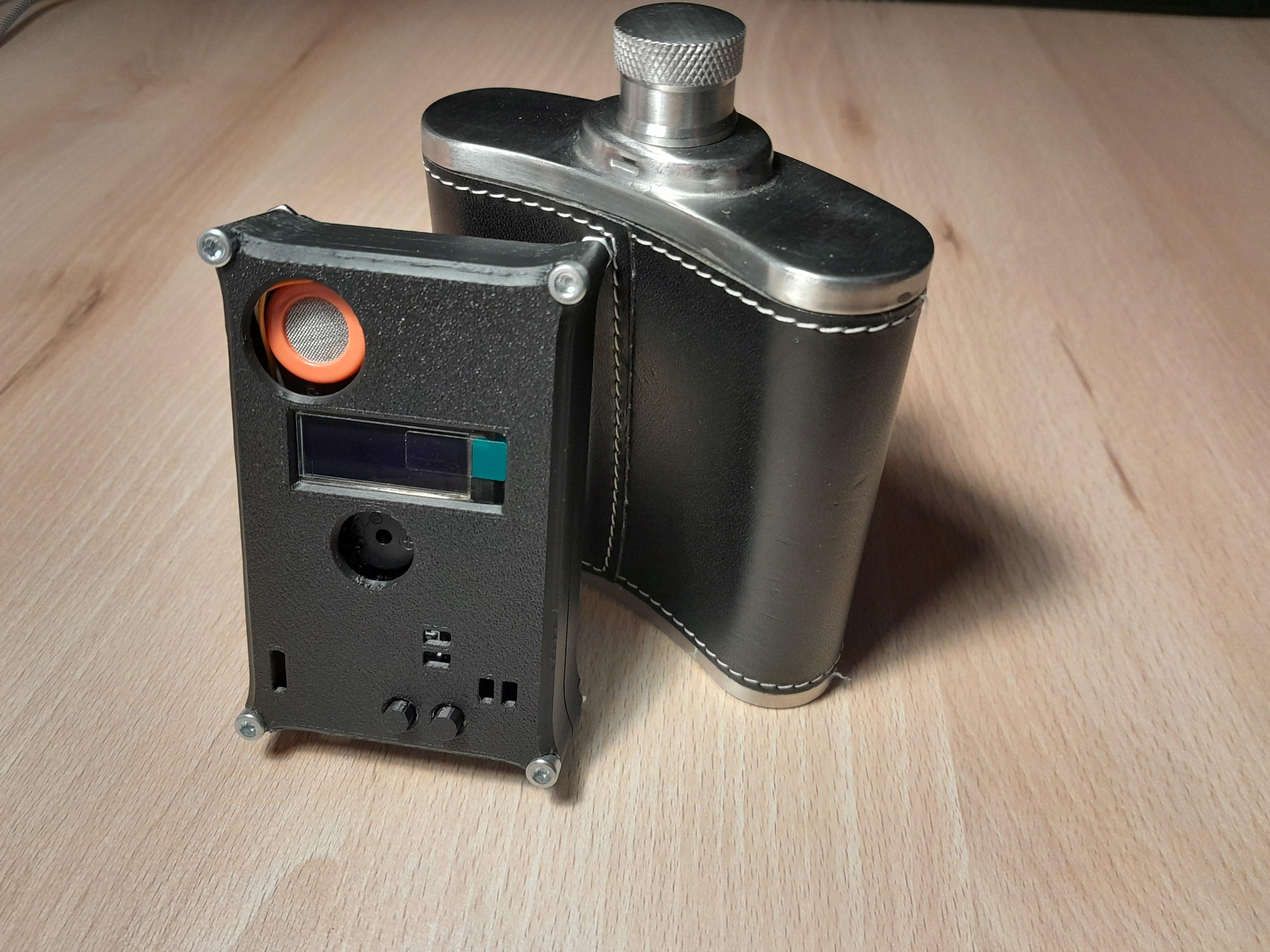
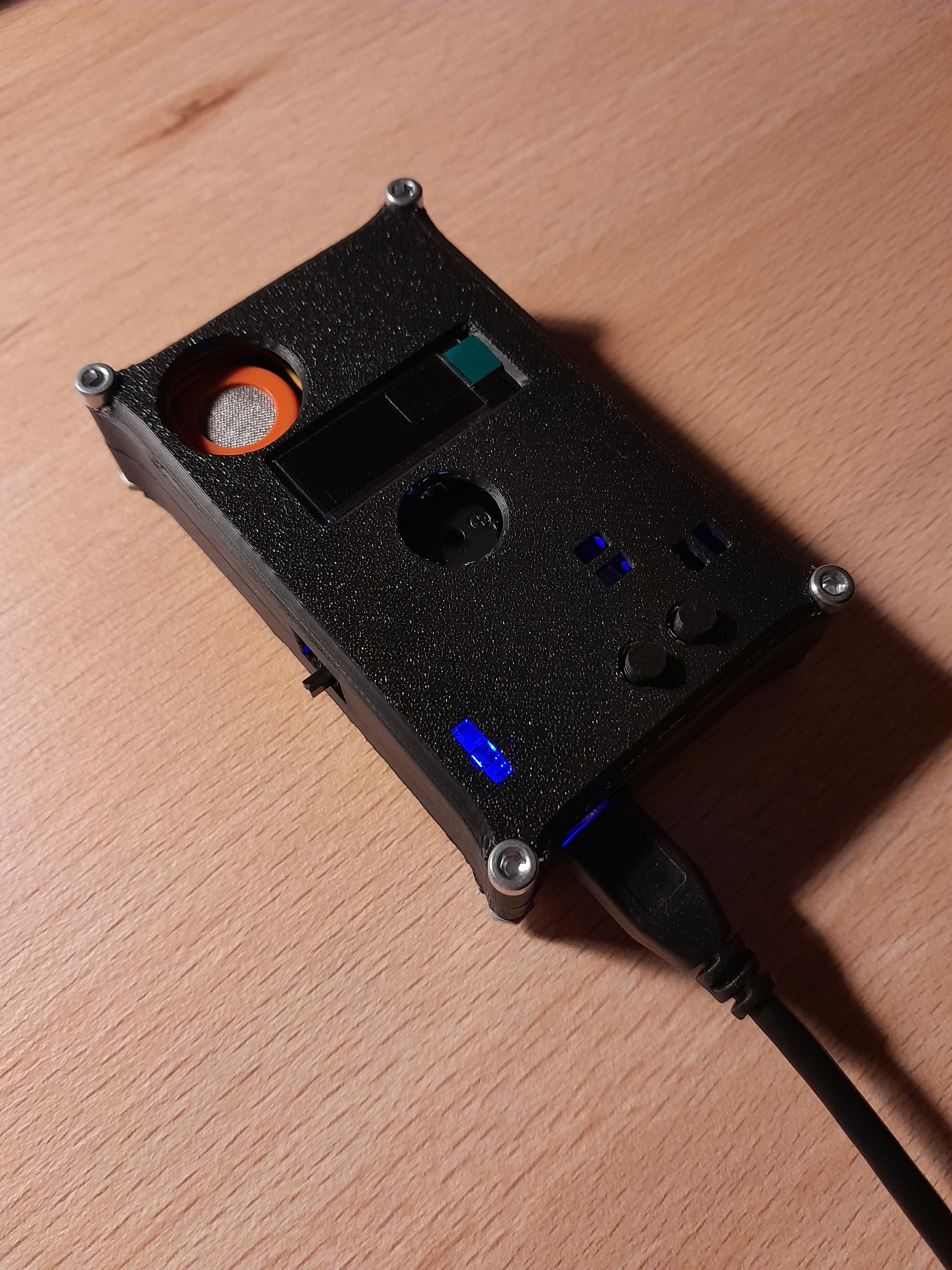
There are a variety of MQ sensors available. I always wanted to create a project with one. After a bit of research I decided to use the MQ3 alcohol gas sensor to create a breath analyzer. As always, circuit boards are perfect for a portable and compact device. PCBWay reached out to me and offered to produce the pcb for this project. Since this device uses smd parts, I do not recommend to build this if you are a beginner at soldering. With that said, let's build one together!
Note: This device may not have good accuracy and should not be used as a way to determine your blood alcohol concentration. Refer to commercial products instead!
All project files can be found on this github repository: https://github.com/KonradWohlfahrt/Breath-Analyzer
Supplies
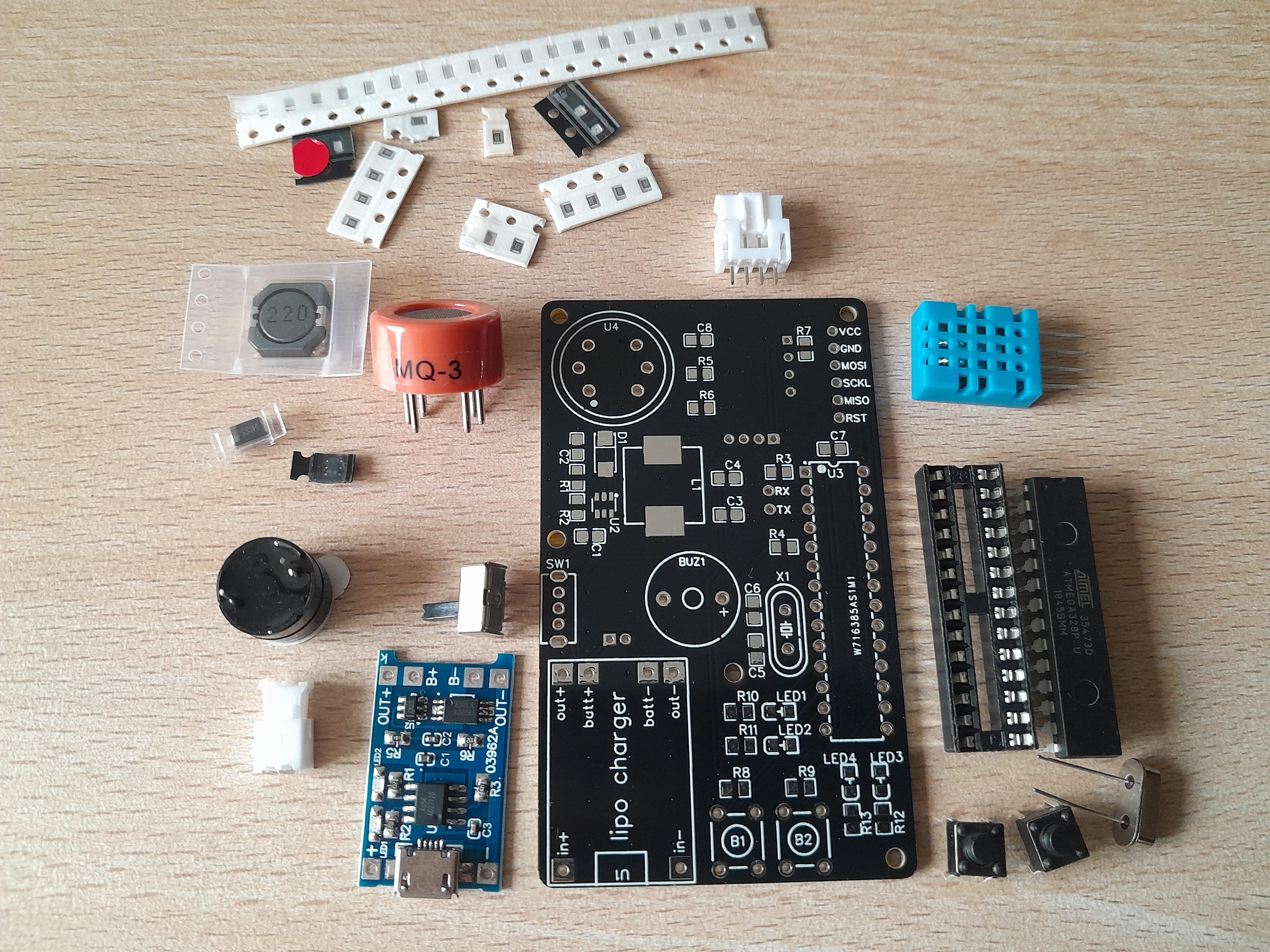
Apart from some electrical tools like a multimeter and power supply, you'll need an Arduino Uno, some Dupont wires and a soldering iron. The list of components can also be found at the repository with the corresponding labels on the pcb.
- custom pcb
- 3d printed case
- 0.91 i2c oled display
- lipo battery
- 2 pin ph2.0 connector (optional)
- TP4056 charging module
- MT3608
- ATmega328p
- MQ3
- DHT11
- 16 Mhz crystall oscillator
- piezo buzzer
- push button
- SK12D07VG6
- 22uH
- SS34
- 2x red led 0805
- green led 0805
- led 0805 (free color choice)
- 22uF 0805 (2x)
- 10uF 0805
- 1uF 0805
- 22pF 0805 (2x)
- 100nF 0805 (2x)
- 220k 0805
- 30k 0805
- 10k 0805 (4x)
- 220r 0805 (optional, connect with solder instead)
- 5.1r or 10r 0805
- 4.7k 0805
- 1k 0805 (4x)
- M2.5 x 12 + nut (4x)
- M3 x 20 + nut (4x)
Designing the Circuit Board
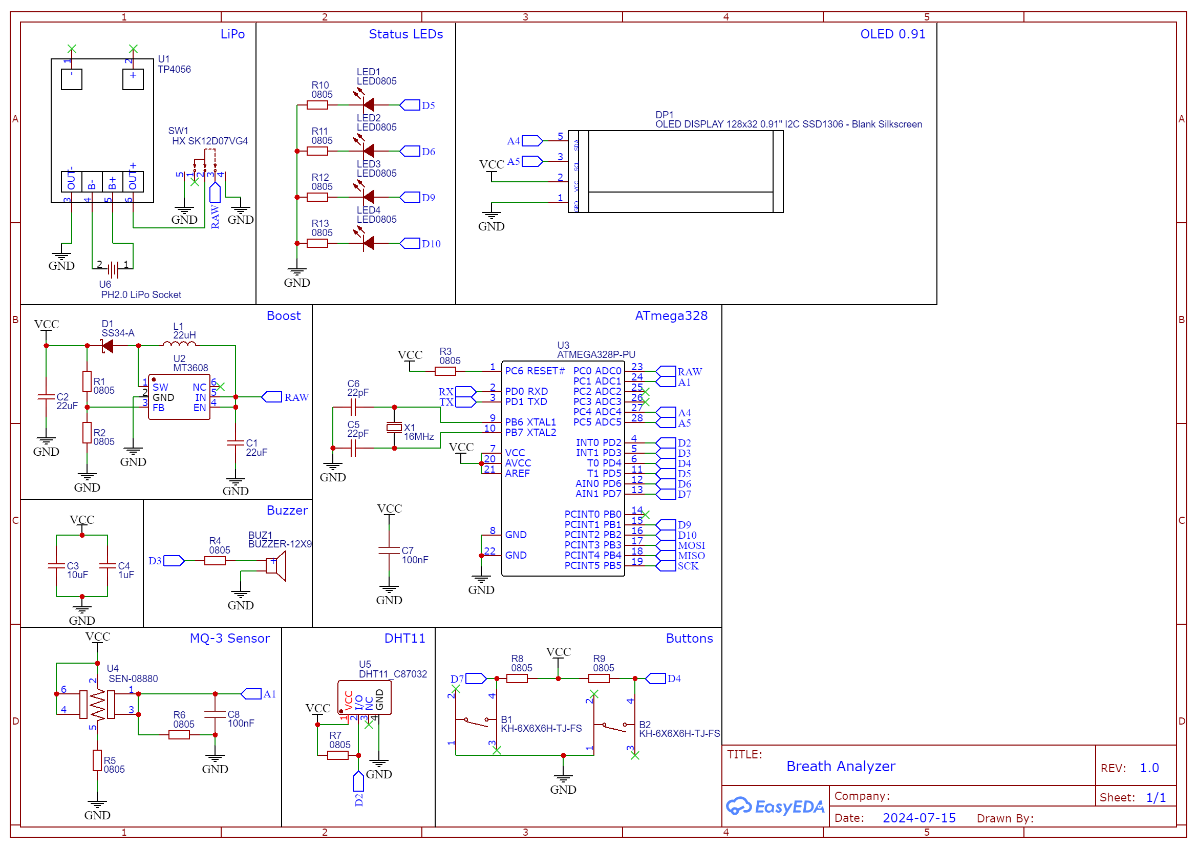
This time the brain of the device will be the ATmega328P (used in Arduino Uno Board). The standalone circuit is simple and doesn't require a lot of components. Apart from the MQ3, there is a DHT11 temperature and humidity sensor, an 0.91 inch oled display, a buzzer, a few leds and two buttons.
The power can be drawn from a lipo battery, which connects to a ph2.0 socket at the bottom. While you can drive the ATmega directly from the battery, the MQ3 requires a voltage of 5V. Boosting the voltage is done by using the MT3608 IC with a few extra components. The resistors R1 and R2 are used to set the output voltage. You can determine them by using the formular in the MT3608 datasheet. I've used 220k (R1) and 30k (R2).
After the schematic was complete, I designed the pcb and ordered it on PCBWay. You can find the gerber files in the projects repository!
Soldering the Boost Converter
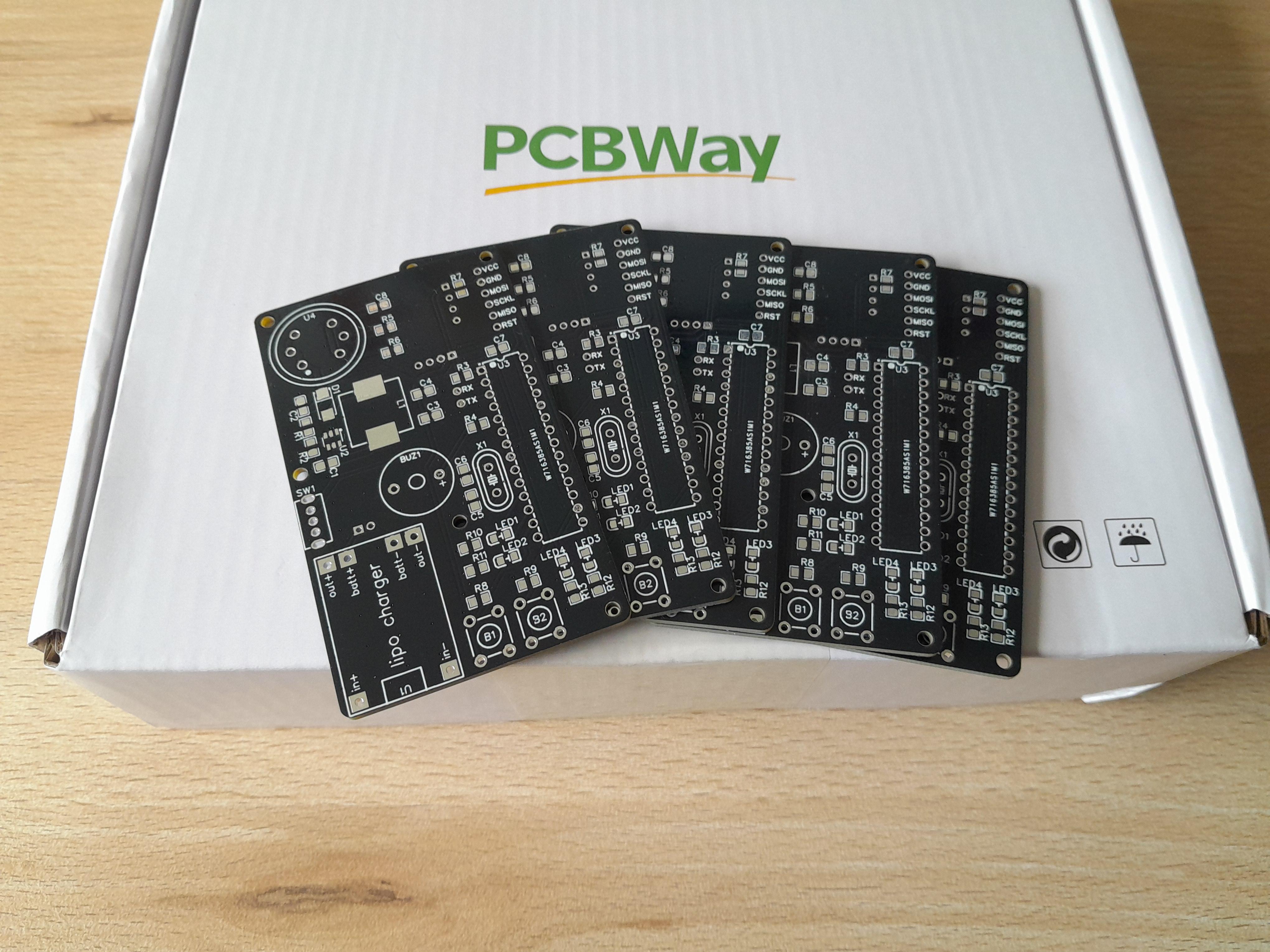

After a few days I received the package with the circuit boards. I was super satisfied with the quality. Especially the finish made them look really shiny! The overall size was perfect for a handheld device and every component seemed to fit. Now I was eager to start soldering.
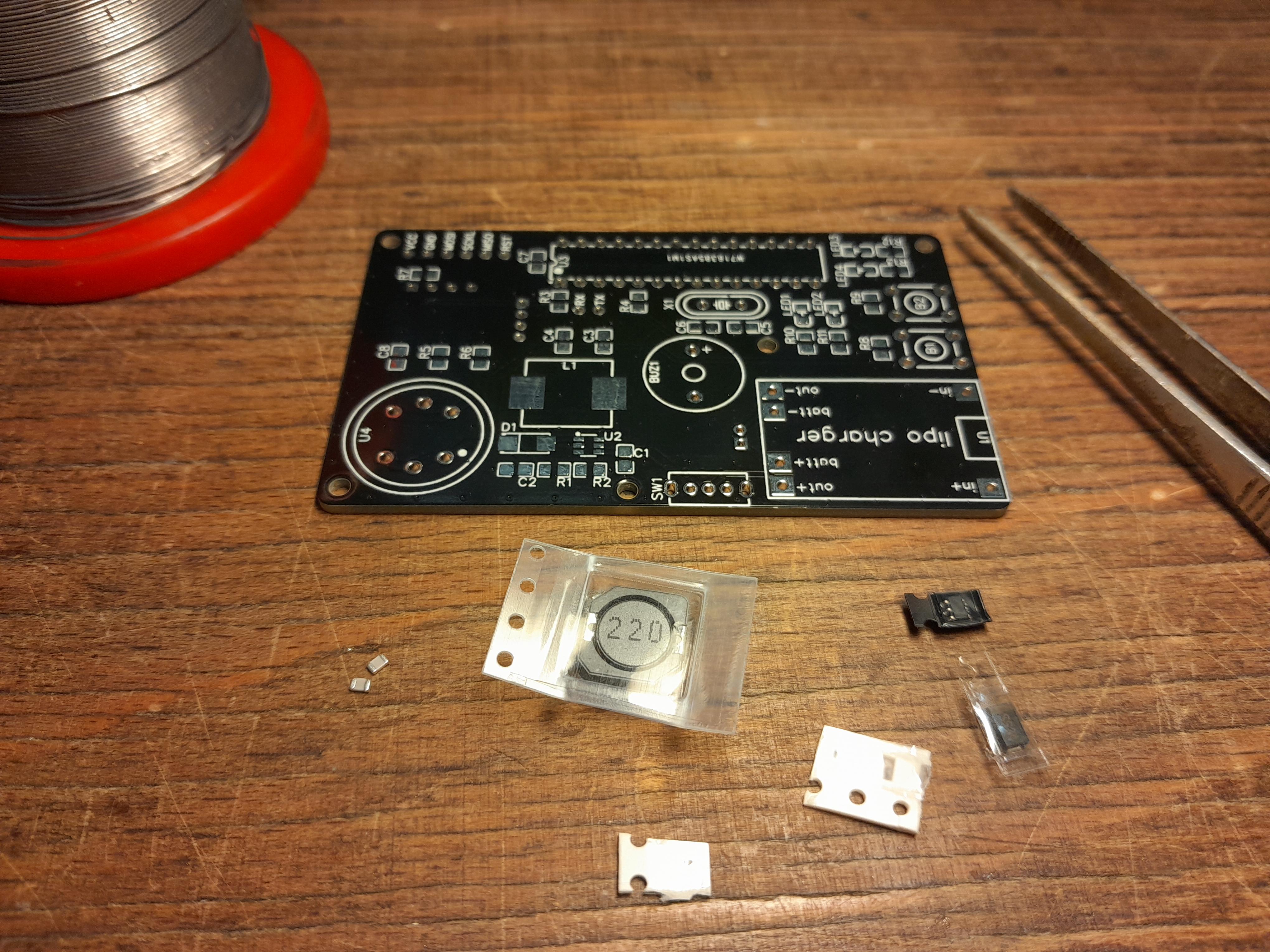
Firstly, I soldered the components of the boost converter, as I had to verify the output voltage. Check out some smd soldering tutorials and practice a little before putting everything together. Start with the ic and then proceed with the bigger parts. Check the image and only solder components on these lables: U2, D1, L1, C1, C2, R1, R2.
Verifying the Voltage
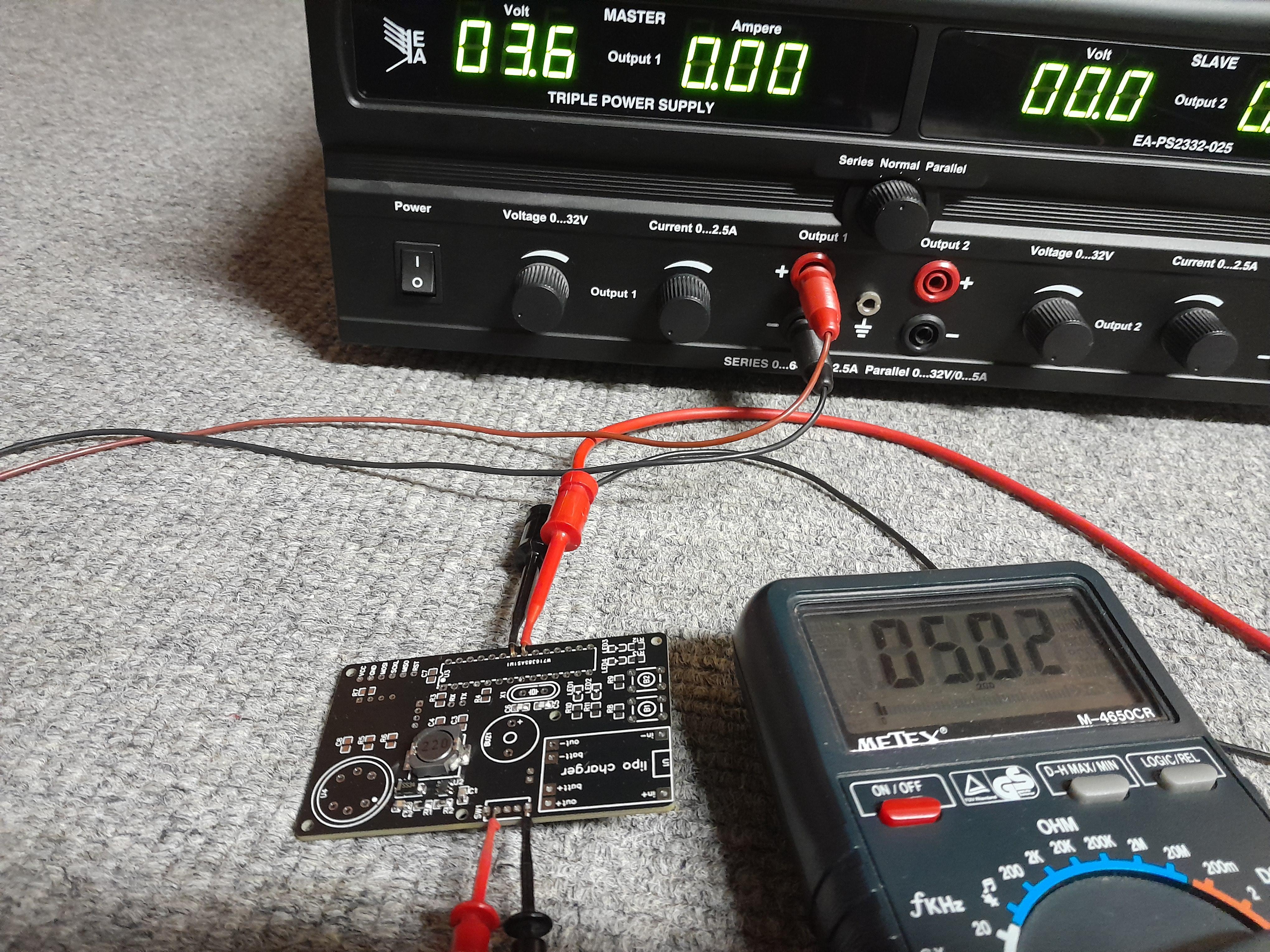
If you don't have a power supply, you might want to skip this step or use the 3.3V of an Arduino Uno board.
Connected power to the on/off switch as seen in the picture and measure the output voltage for a variety of input voltages (3.0V - 4.2V). I measured a stable output voltage of 5.02V. You should write down your value, as we need it later.
Soldering and Printing
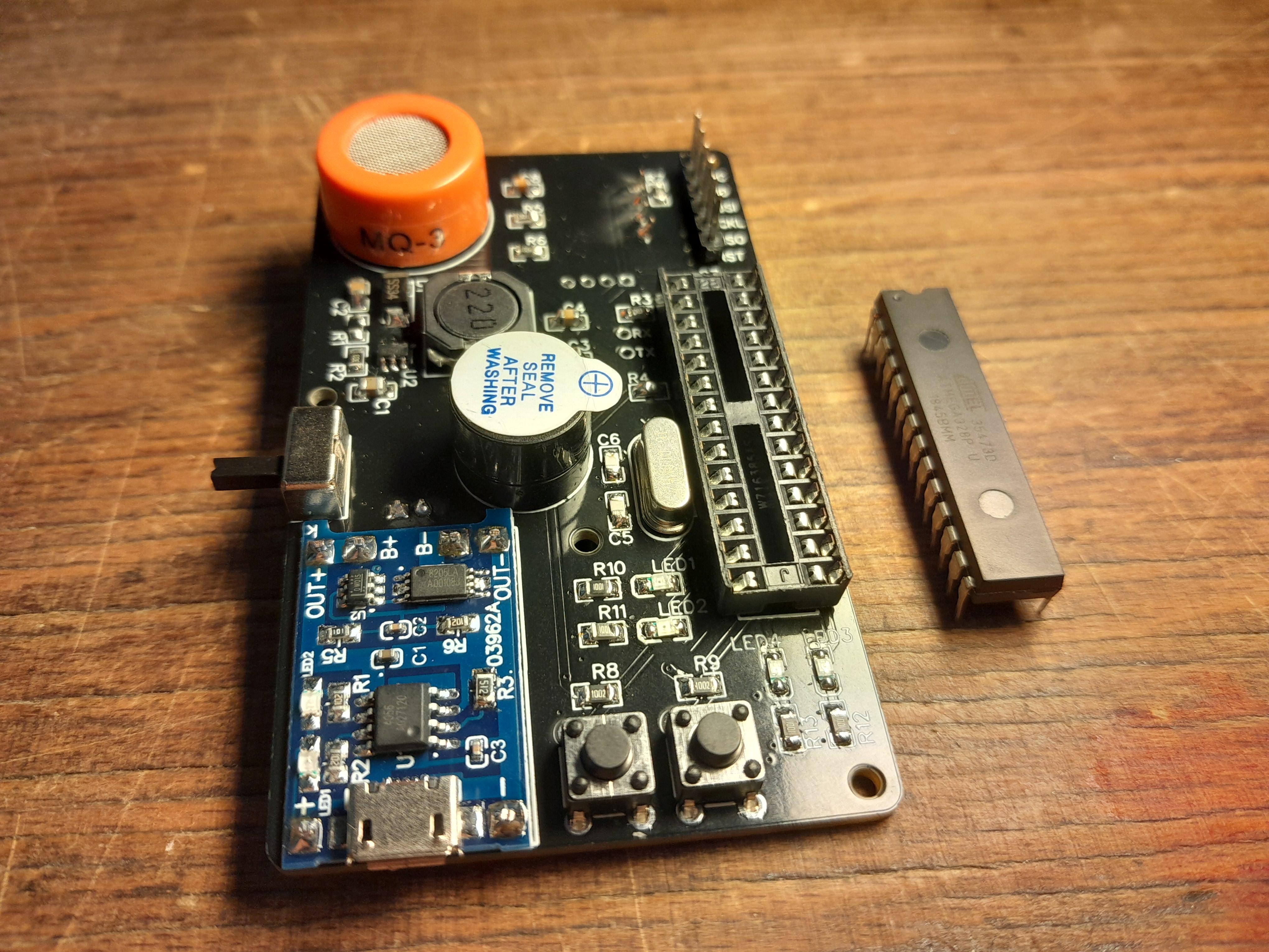

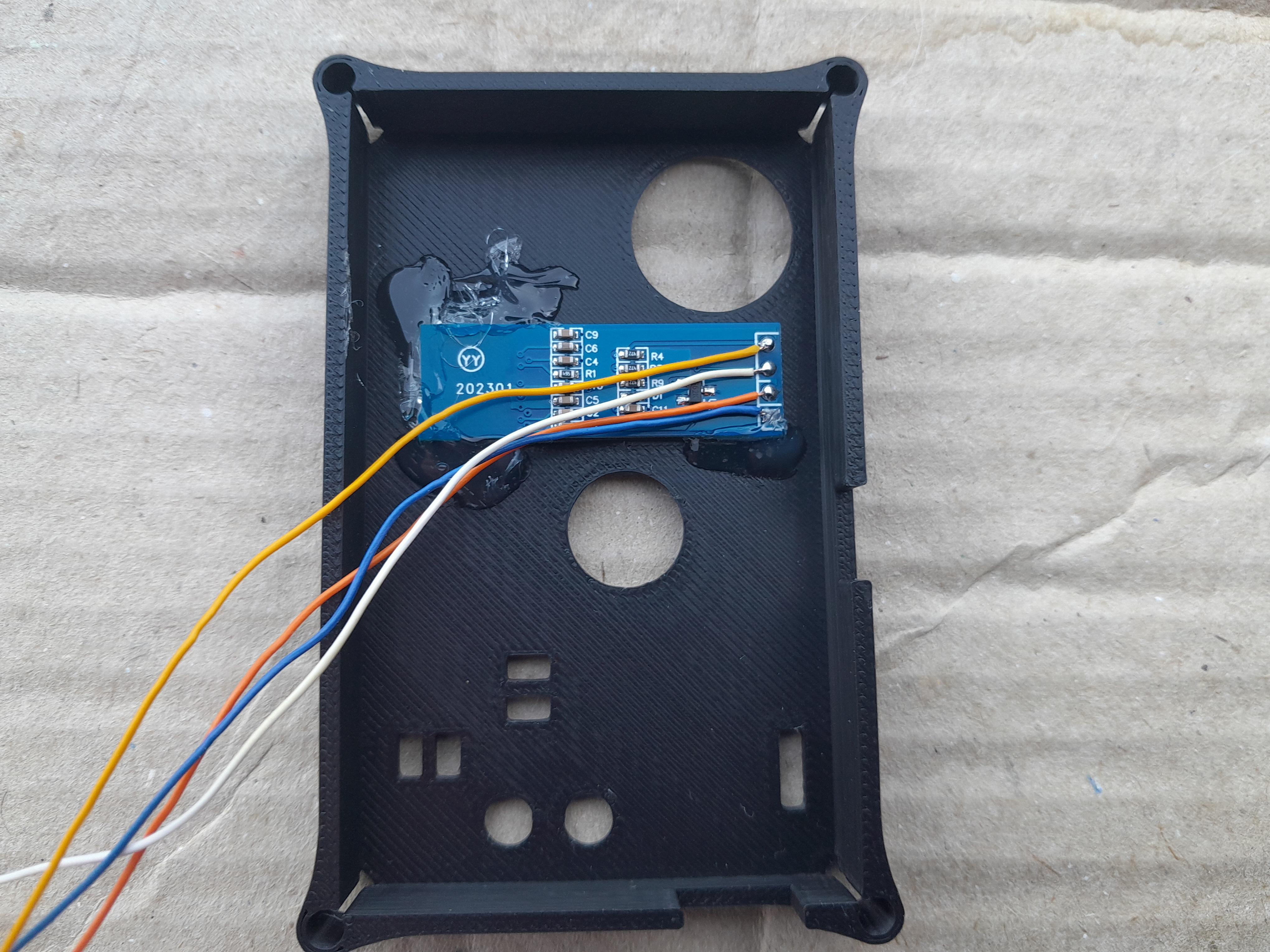
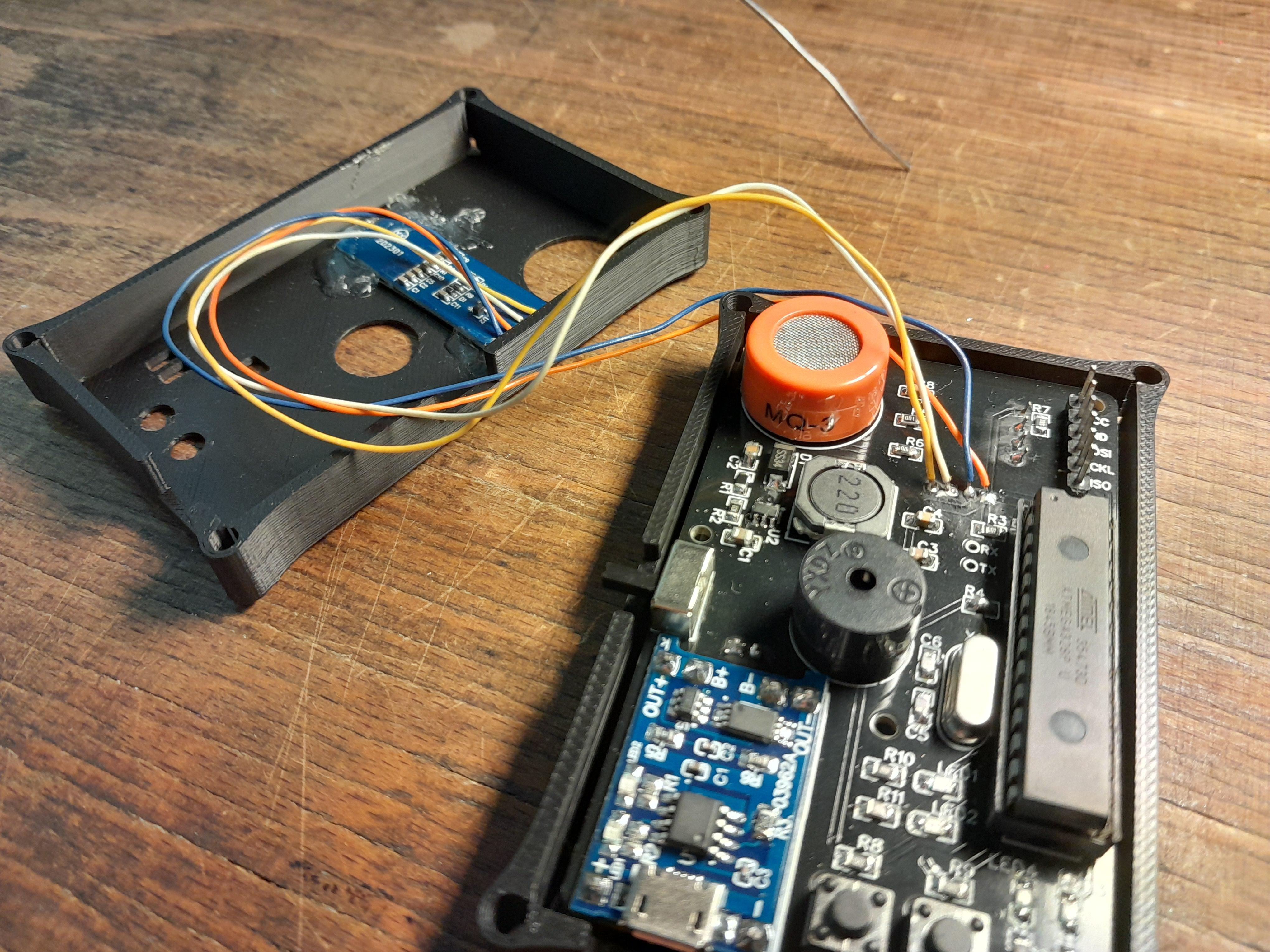
With a stable 5V output, you can solder the other components. Begin with the remaining smd parts and add the through-hole ones afterwards. I've bend the DHT11 sensor to make the final design more compact. If you don't want to use the ph2.0 connector, just connect the battery to the pins directly! Add pins to VCC, GND, MOSI, SCKL, MISO, RST to flash the ATmega. You don't need pins on rx and tx. Depending on your battery, you might want to change the charge programming resistor of the TP4056 module. Here is a great video showing you how to do that. Check the datasheet or use my rule of thumb: The output current should be below the max capacity of the battery. E.g. for a 500mAh battery you should use a 3k resistor (charge current=400mA < 500mAh).
While you solder it is a good idea to start printing the case. Once that is done, you can glue in the oled display (cables added beforehand) and finally connect the oled cables and pcb. Version 2 of the pcb has proper lables for each connection.
Testing
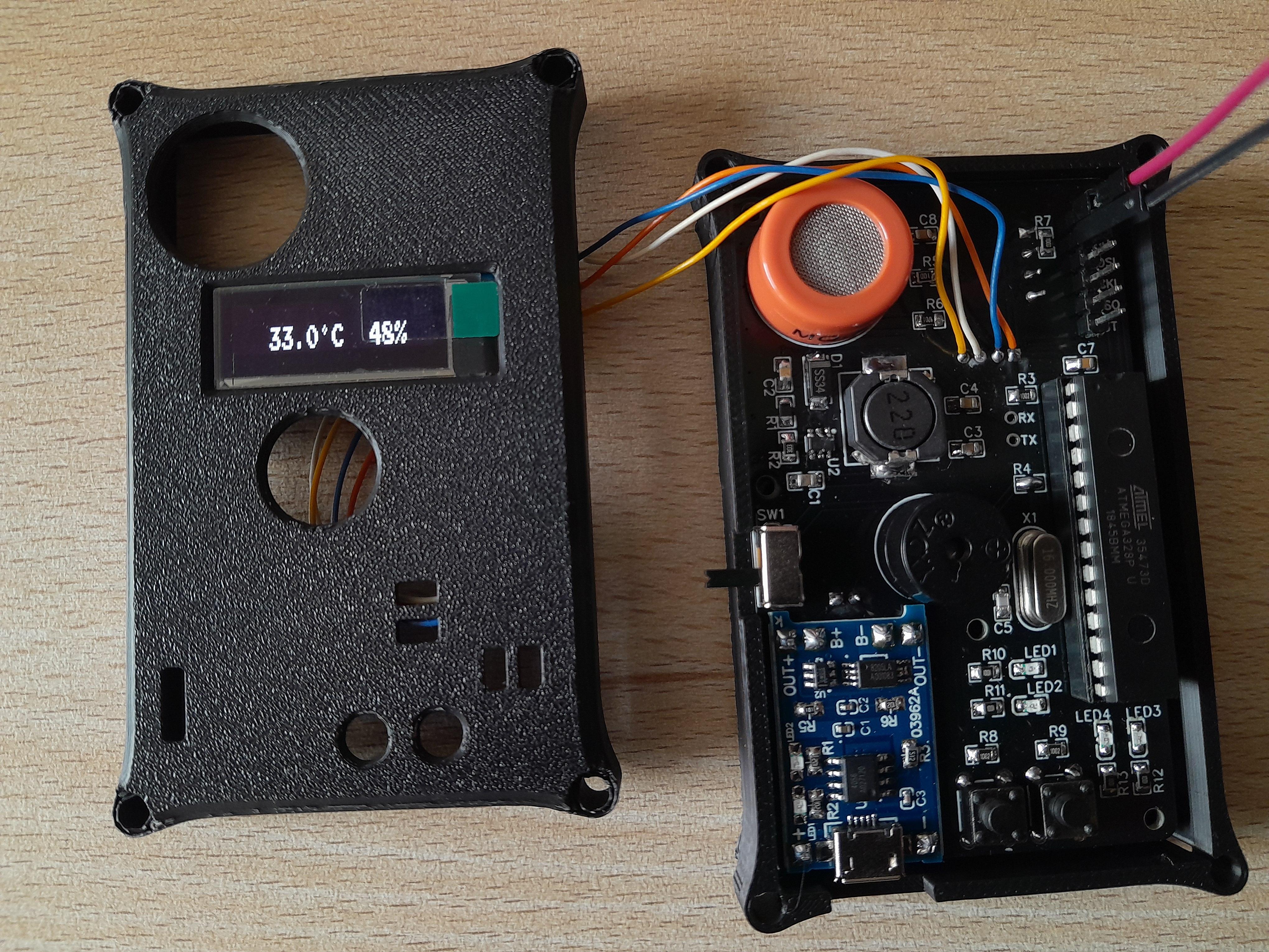
Great! The hardware part is complete and now we can start testing the circuit. First of all, I burned the bootloader and uploaded a test sketch to the ATmega by utilizing the Arduino Uno as an ISP programmer. You can check out this blog or this video if you don't know how to burn the bootloader/upload code to a standalone chip. The test sketch can also be found at my repository. It will monitor some values. You'll have to import the 'u8g2' and 'dht11' libraries before uploading the sketch.
If you see a number printed on the screen, everything works! You can toggle between different modes by pressing any button:
- analog read from sensor
- voltage of the sensor
- resistance of the sensor (Rs)
- bac in per mille
- temperature and humidity
You might discover that the values, especially the bac is too high! That's because the sensor has to be heated up once for over 24 hours! If you leave it powered off for too long, you'll have to repeat this step. You should not use a battery, as they will probably run out of power quite fast. I left mine connected to the Uno and waited some time. After that, your analog value should be in the range of 100 to 400. Now you can divide the resistance of the sensor (Rs) by 60 and put the result into R0 of the sketch and upload it again. The sensor is now "calibrated" and the bac reading should be much more reasonable.
I have assumed that you kept the sensor in clean air during this whole process ;)
How to Calibrate
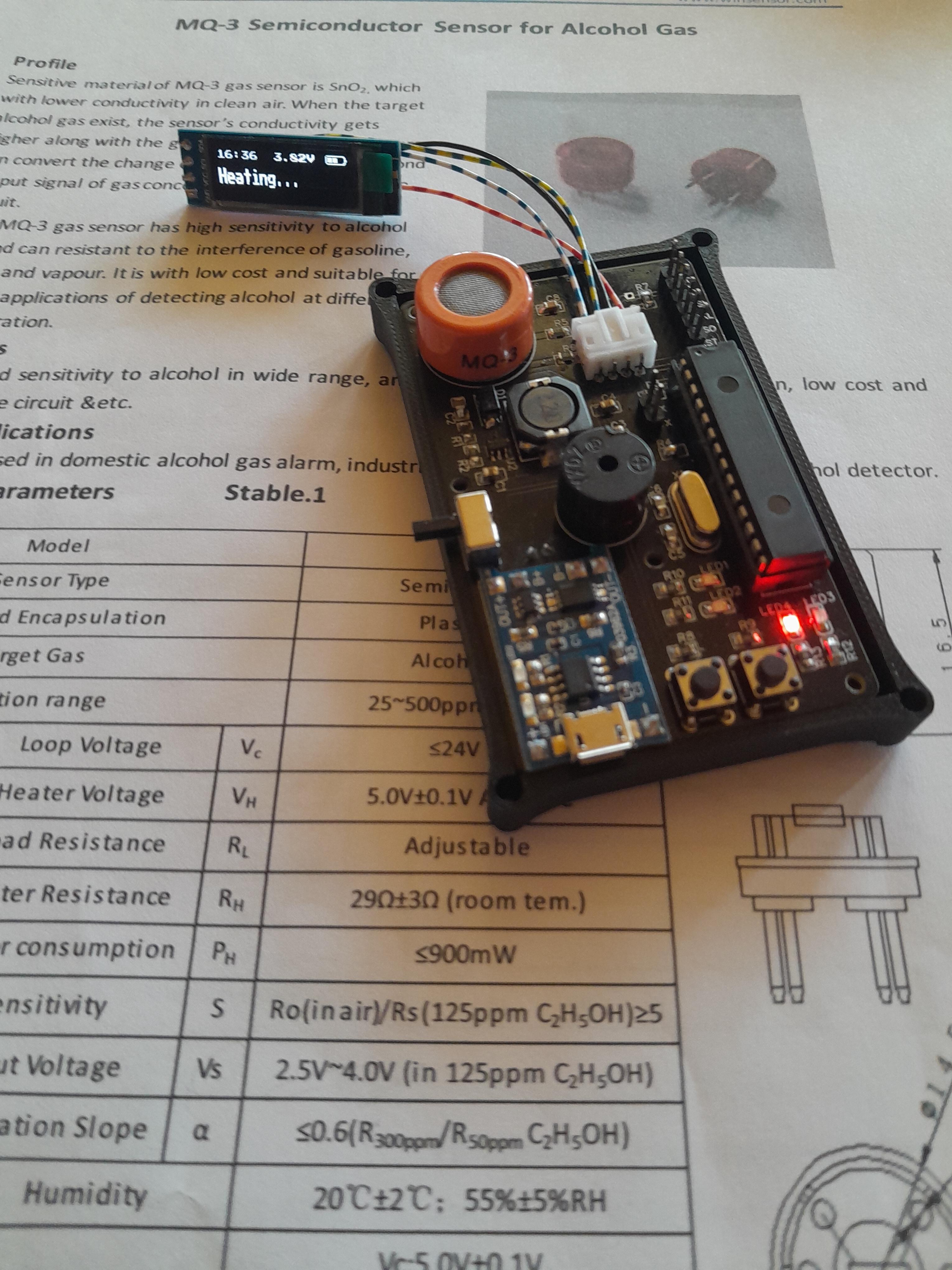
The most time consuming and frustrating part of the project was to learn how to calibrate the sensor. There are multiple datasheets out there and a few blog entries. I've combined everything I found and came up with a (hopefully) decent solution! Let me sum up my findings:
When exposed to gas, the sensor will decrease in resistance and thus more current will flow. This effect can be measured by a microcontroller via an analog gpio. The sensor is connected with a resistor (RL) in series to create a voltage divider. To calculate the gas concentration in ppm, we have to know the resistance of the sensor. By using the voltage divider formular and the formular 'adc/1023*5V' to calculate the voltage on an analog input, we can rearrange them to get the following:
Rs = RL * (1023 - adc) / adc
The ratio between the sensor resistance in the target gas and the clean air resistance (R0) is used to determine the ppm value. R0 can be obtained by calculating Rs in clean air and divide by 60. The magical number 60 is derived from the air curve from the Seeed datasheet. With a constant R0, we can now calculate the ratio.
The blog from Electronoobs helped to determine a formular for the alcohol gas concentration curve. I only made some changes to the points in the graph.
P1(50ppm, 0.17 Rs/R0)
P2(500ppm, 0.0225 Rs/R0)
With these lines of code we can obtain the concentration in ppm.
const float point1[] = { log10(50), log10(0.17) };
const float point2[] = { log10(500), log10(0.0225) };
const float scope = (point2[1] - point1[1]) / (point2[0] - point1[0]);
const float coord = point1[1] - point1[0] * scope;

float getConcentration(float resistance) { return pow(10, coord + scope * log(resistance / R0)); }
With the concentration we can calculate a value for mg/l.
1 part/million (ppm) = 0.9988590004 mg/L
To get a value for per mille, multiply the mg/L value with 2. Remember to heat up the sensor. This makes a huge difference!
More detailed explanations:
Finalizing

Before uploading the final sketch to the chip, we have to make some changes to the sketch. Open up 'BreathAnalyzer.ino' and go to line 25. You should change the 5.0f to your measured value from earlier (e.g. 5.02f for me). After you've changed this line the values from line 27 to 30 have to be updated as well (calculate by: 3.9V / 5.02V * 1023, ...). You don't have to change these values, but the voltage readings will be more accurate.
Now upload the sketch and disconnect all the cables from the pcb. Plug in the battery and flip the switch. It should finally work!
The device will heat up for 30 seconds and then show a start screen with the temperature and humidity, as well as the battery status. Wait for a bit of time and the device goes into sleep mode. Press any button to wake it up. Pressing any button at the start screen will take a measurement and display them to the user. Use this to determine your bac. Like the test sketch we have to set a value for R0, but not via code this time. The value will be saved in the eeprom and has to be obtained once by calibrating (in the settings mode).
Enter the settings mode by pressing both buttons. You can toggle between the different settings with the left button and change the values with the right button. You can exit the settings mode by pressing both buttons once again. The values will be saved persistently in the eeprom. Turning off the Breath Analyzer will not reset them! You can switch between the following:
- activate/deactivate buzzer
- contrast of the display
- calibrate (will heat up, take samples and calculate R0, only use in clean air)
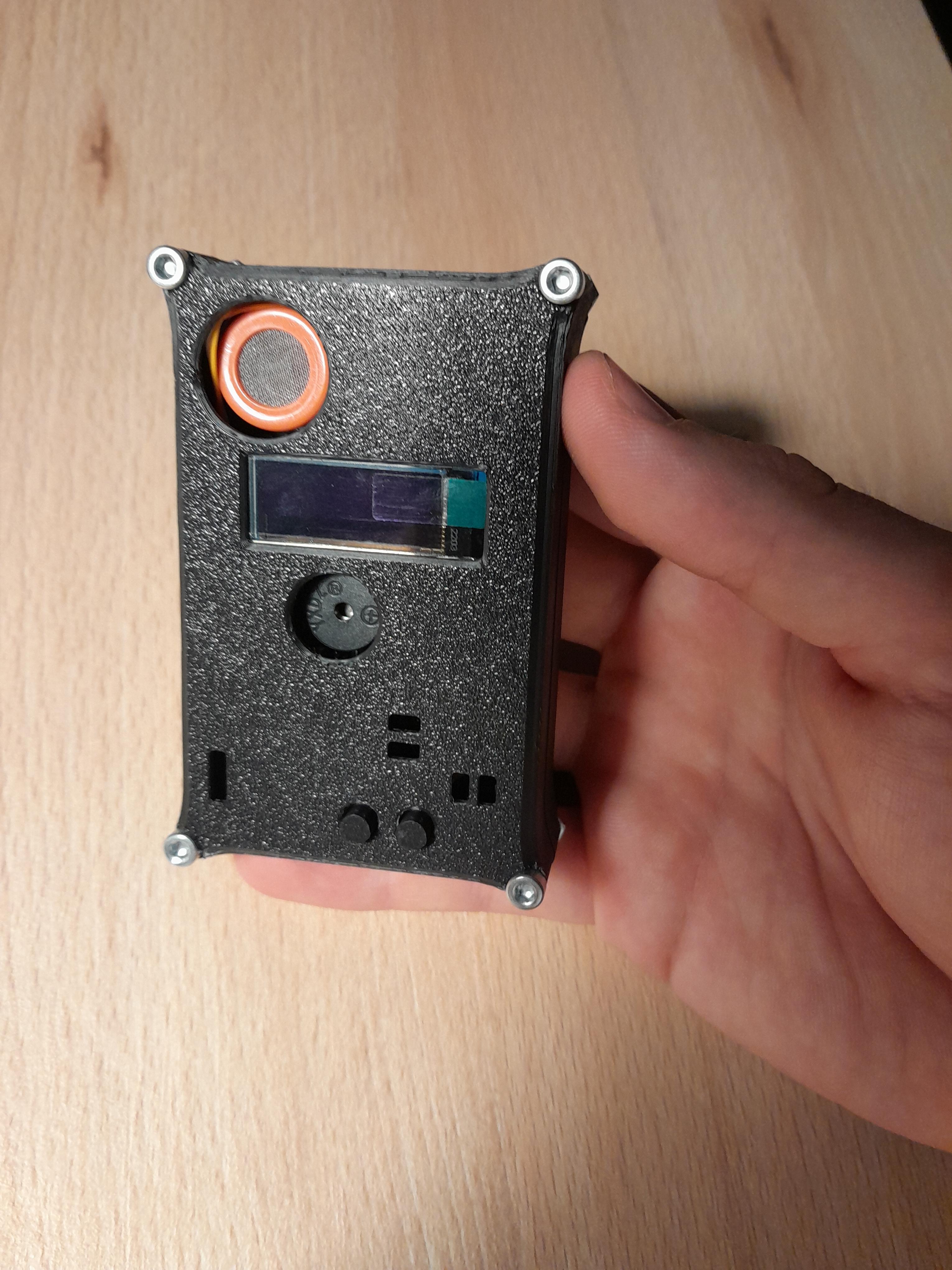
You can secure the pcb with four M2.5x12 screws and nuts to the bottom and then combine bottom and top with four M3x20 screws and nuts. That should be it! Now you have yourself a DIY Breath Analyzer and a better understanding on how to work with MQ sensors!
Finally, special thanks for PCBWay for supplying me with awesome quality pcbs!
Cheers