DIY ESP32 Desktop Companion Robot 🤖
by Ideas by Suyash Desai in Circuits > Arduino
327 Views, 0 Favorites, 0 Comments
DIY ESP32 Desktop Companion Robot 🤖

.jpeg)
I wanted to build something that was more than just another ESP32 project.
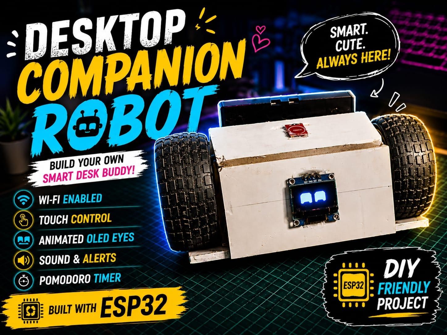
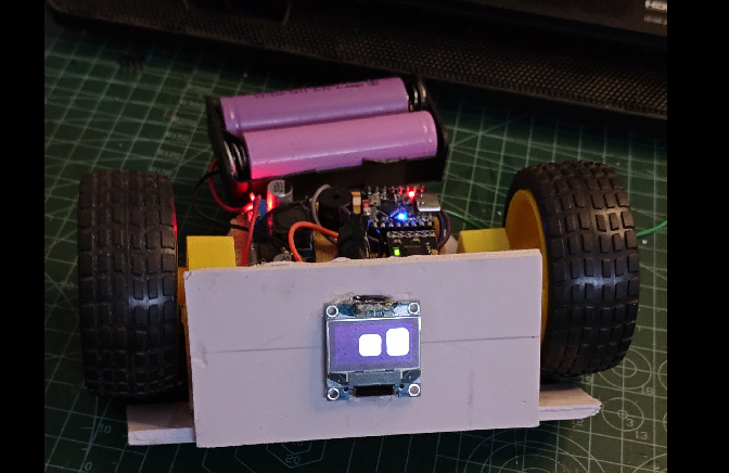
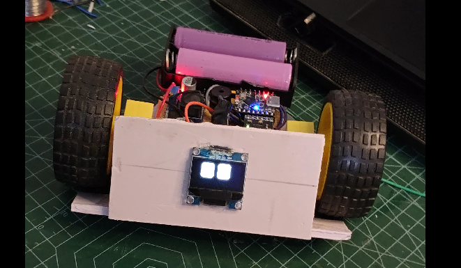
So I built a small Desktop Companion Robot that can move around, display animated eyes, react to touch, connect to Wi-Fi, and be controlled from a phone through a web dashboard. The robot is powered by an ESP32-C3 Mini and uses an SSD1306 OLED to display animated RoboEyes. It features multiple moods and expressions, touch interaction, Wi-Fi control, movement, sound feedback, and a built-in Pomodoro focus mode. Through the custom web dashboard, I can control the robot's movements, expressions, moods, and focus sessions directly from my phone.
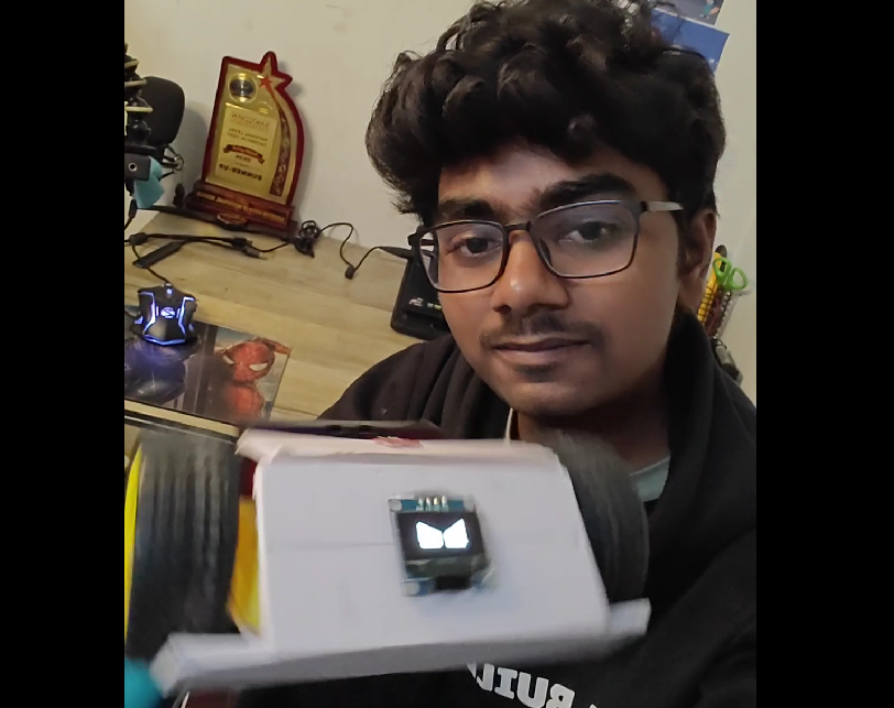
The robot can also react to user interaction, making it feel less like a simple electronics project and more like a tiny desktop companion with its own personality.
The project combines embedded systems, robotics, IoT, electronics, programming, web development, and 3D design into one small desktop robot.
Supplies
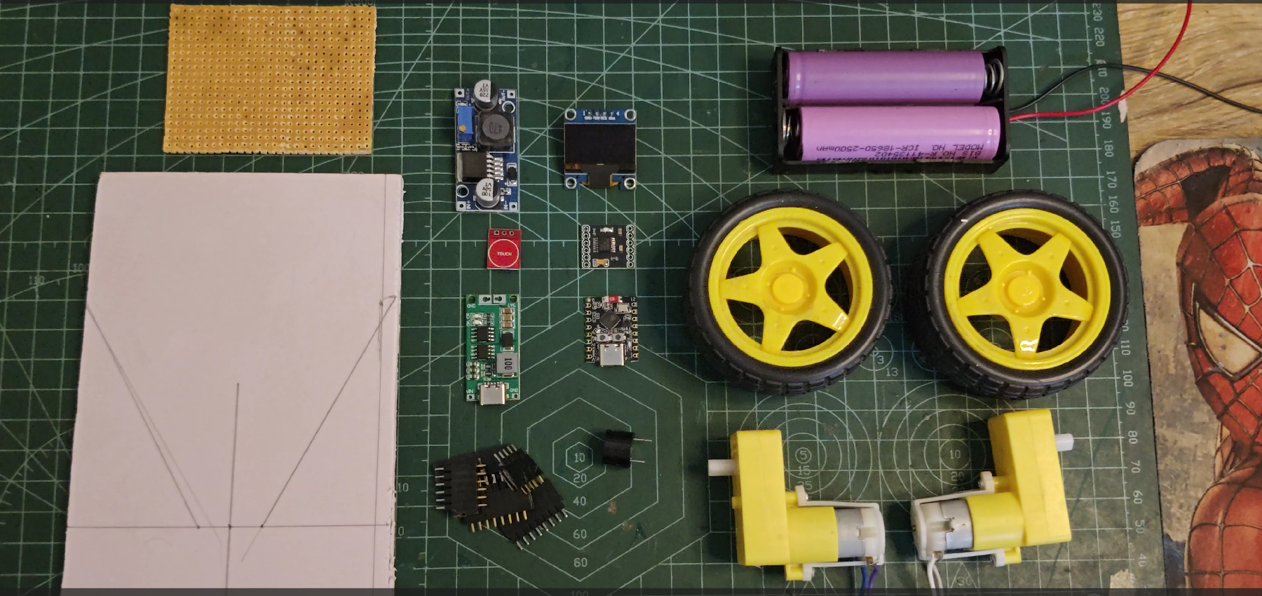
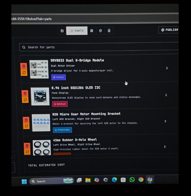
ESP32-C3 Mini * 1
SSD1306 128×64 OLED Display * 1
DRV8833 Motor Driver * 1
N20 Geared DC Motor * 2
Robot Wheels * 2
Caster Wheel * 1
TTP223 Touch Sensor * 1
Active Buzzer * 1
18650 Li-ion Battery * 2
2S 18650 Battery Holder * 1
LM2596 Buck Converter * 1
Power Switch * 1
Jumper Wires * 1 set
Connecting Wires * 1 set
Screws & Fasteners * 1 set
3D Printed Enclosure * 1
Planning With Blueprint AI
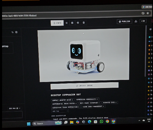
Before assembling the robot, I needed to figure out the hardware, wiring, enclosure, and overall build plan.
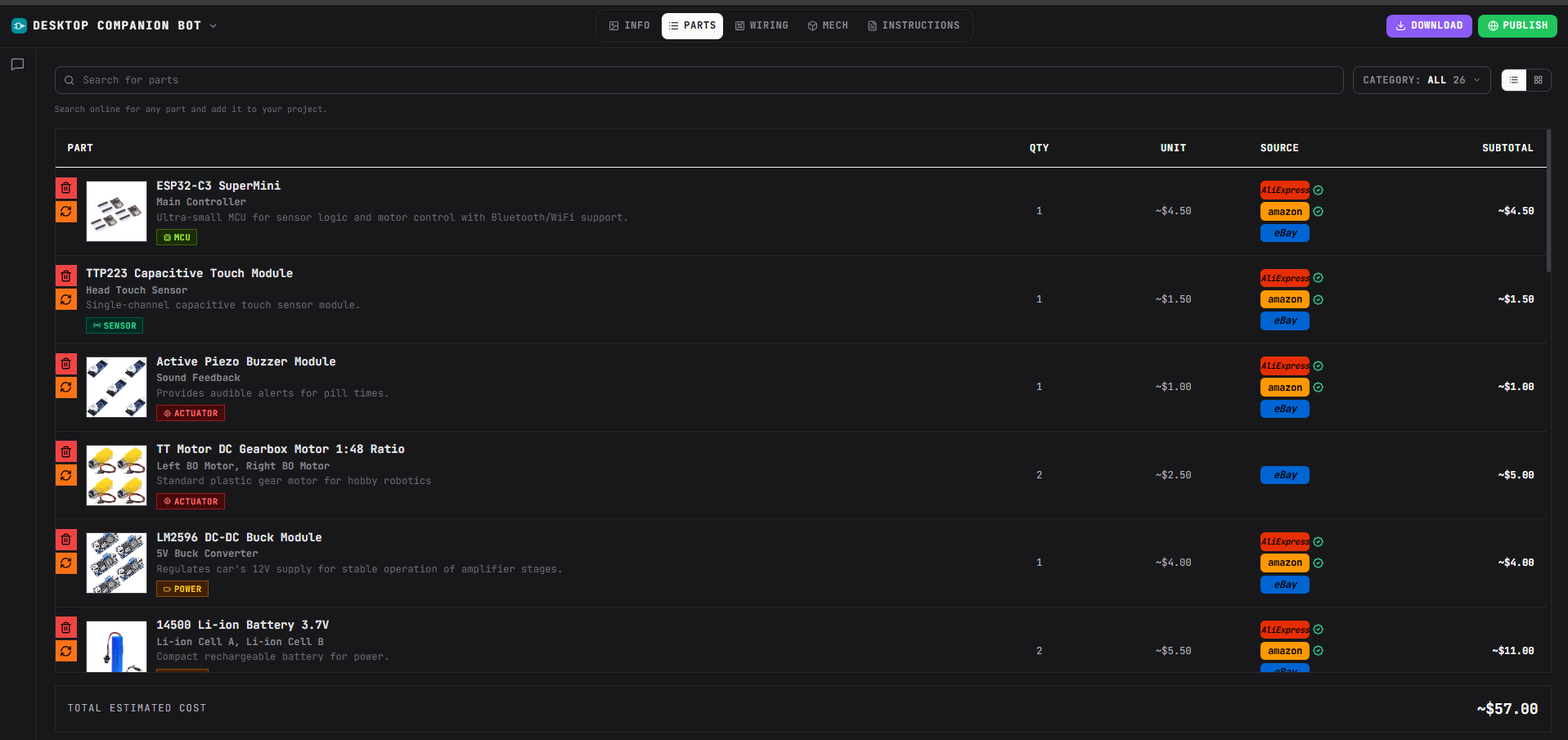
Instead of figuring everything out separately, I used Blueprint AI, an AI tool designed for building hardware projects. I described my idea and requirements in a single prompt, and Blueprint helped me turn the concept into a practical build plan.It helped me with:
- 📋 Bill of Materials (BOM) — components and quantities
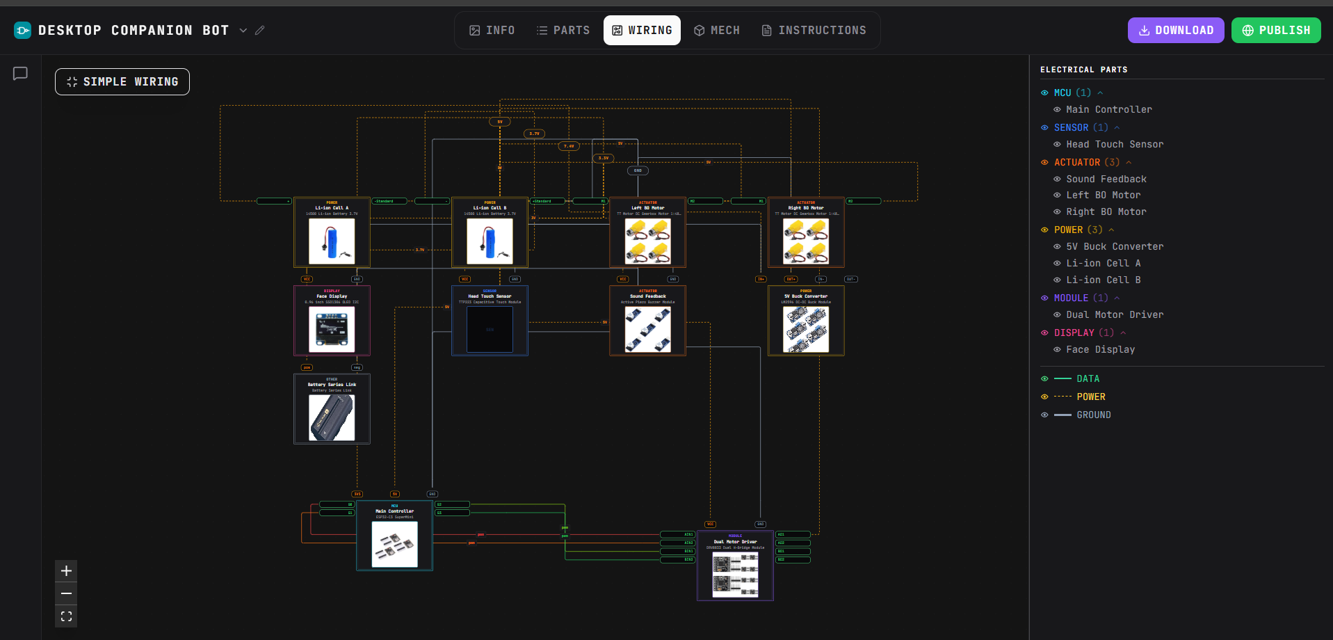
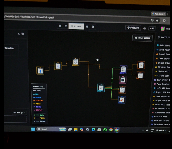
- 🔌 Wiring diagrams — how the different modules connect
- ⚡ Hardware architecture — planning the electronics around the ESP32
- 🧩 Build instructions — step-by-step guidance
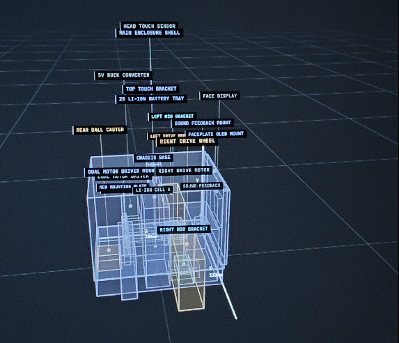
- 📐 3D enclosure concept — designing the physical structure of the robot
This gave me a starting point before I bought and assembled the components.
My Blueprint Workflow
Idea → Blueprint AI → BOM → Wiring → Enclosure → Build → Test
I still had to validate the design, adapt it to the components I had, and troubleshoot things during the actual build. But having the initial hardware plan made the process much easier.
Why I Used Blueprint
For me, the biggest advantage was being able to go from "I have an idea" to having an actual hardware plan without spending hours figuring out every connection from scratch.
If you're building ESP32 projects, Arduino projects, IoT devices, robots, or other DIY electronics, you can use Blueprint to help plan the project before starting the physical build.
BluePrint:
Wiring
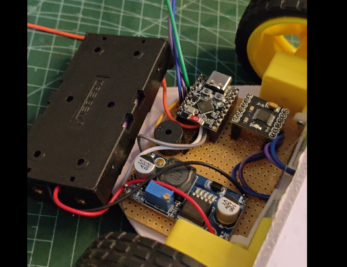
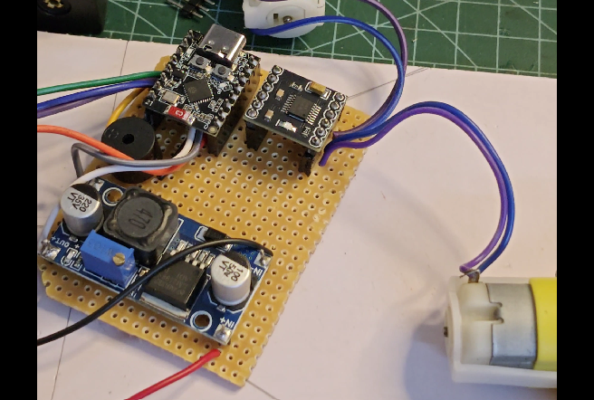
The SSD1306 OLED communicates with the ESP32-C3 over I²C.
The TTP223 touch sensor is connected to a digital GPIO and provides the robot with physical touch interaction.
The DRV8833 controls the two geared DC motors, allowing the robot to move forward, backward, and turn.
The buzzer is connected to another GPIO and is used for audio feedback and notifications.
The batteries provide power to the robot, while the LM2596 buck converter regulates the voltage required by the electronics.
Important: Before connecting the ESP32, always verify the output voltage of the buck converter using a multimeter.
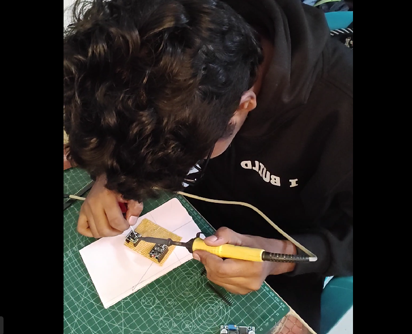
Once everything was wired, I tested each component individually before putting everything inside the enclosure.
Wiring Connections
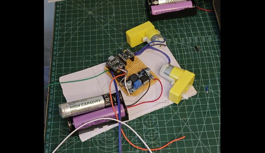
Pin Connections
SSD1306 OLED Display
- VCC → 3.3V
- GND → GND
- SDA → GPIO 8
- SCL → GPIO 9
TTP223 Touch Sensor
- VCC → 3.3V
- GND → GND
- OUT → GPIO 3
Buzzer
- Positive (+) → GPIO 2
- Negative (-) → GND
DRV8833 Motor Driver
- AIN1 → GPIO 4
- AIN2 → GPIO 5
- BIN1 → GPIO 6
- BIN2 → GPIO 7
- GND → GND
- VM → Battery Positive (+)
Motor 1
- Motor wires → AOUT1 & AOUT2
Motor 2
- Motor wires → BOUT1 & BOUT2
Power
- Battery Positive (+) → DRV8833 VM
- Battery Negative (-) → GND
- Battery → LM2596 Buck Converter
- LM2596 regulated output → ESP32-C3 Mini power input
Important: Make sure all GND connections are common. Also, verify the buck converter's output voltage with a multimeter before connecting it to the ESP32.
Assemble the Robot
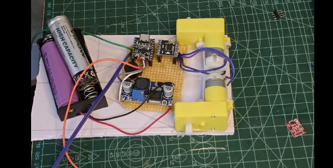
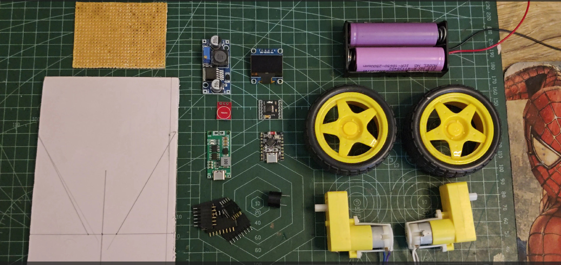
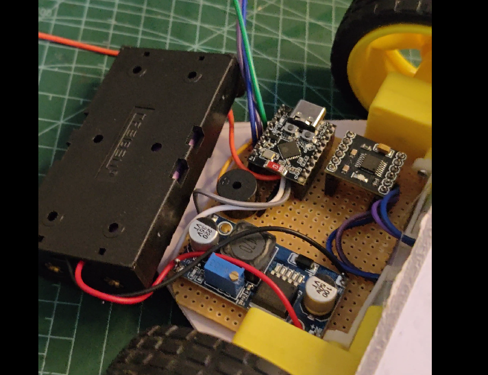
After testing the electronics, I started assembling the physical robot.
First, I mounted the two geared motors on the sides of the enclosure and attached the wheels. A caster wheel was added on the opposite side to support the robot while allowing it to turn easily.
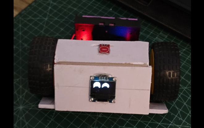
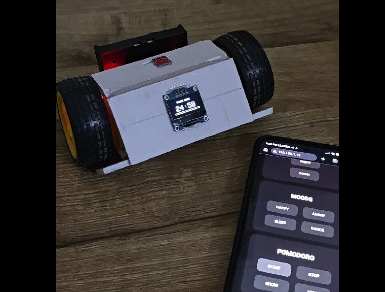
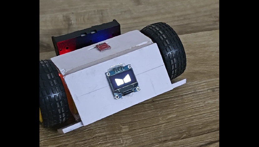
The OLED display was positioned at the front because it acts as the robot's face.
I then placed the ESP32-C3, motor driver, buck converter, battery holder, touch sensor, and buzzer inside the enclosure.
I tried to keep the wiring as organized as possible and made sure the battery and exposed connections couldn't accidentally short against other components.
The final arrangement looks roughly like:
Front → OLED / Eyes
Middle → ESP32 + Motor Driver
Bottom → Battery
Sides → Motors + Wheels
Before closing the enclosure, I powered the robot and checked that all the components were still working correctly.
Program the ESP32 & Add RoboEyes
.png)
.png)
.png)
.png)
Now it's time to bring the robot to life.
I programmed the ESP32-C3 Mini using Arduino IDE and added the required libraries for the OLED, Wi-Fi, web server, and RoboEyes.
The OLED uses the RoboEyes library to create animated eyes instead of displaying simple static graphics.
The robot can have different expressions such as:
- Happy
- Sad
- Angry
- Sleeping
- Normal
- Focus mode
The ESP32 changes the eye animation depending on what the robot is doing.
For example, when the robot is idle, the eyes can look around and blink naturally. When the user interacts with it, the robot can change its expression or trigger a different animation.
I also programmed the motor controls, touch sensor and buzzer so that all of these systems work together.
The basic software flow is:
ESP32 starts → Initialize hardware → Connect to Wi-Fi → Start web server → Read commands → Control robot → Update display/expression
Here's Code: https://github.com/astrix884/desktop-companion-robot.git
Add Wi-Fi Control & Pomodoro Mode
One of the main features of this project is that I don't need a dedicated mobile application to control the robot.
The ESP32 runs a web server, which provides a custom control dashboard that can be opened directly from a phone.
From the dashboard, I can:
- Control the robot's movement
- Change its mood
- Trigger different expressions
- Start the Pomodoro timer
- Trigger different robot actions
The communication works like this:
Phone → Wi-Fi → ESP32 → Robot
I also added a Pomodoro focus mode so the robot can act as a small study/work companion.
The robot can run a focus timer and provide visual/audio feedback when the focus or break period changes.
This makes the robot more than just a moving OLED display—it becomes an actual interactive desk companion.
Test Everything & Its Ready!
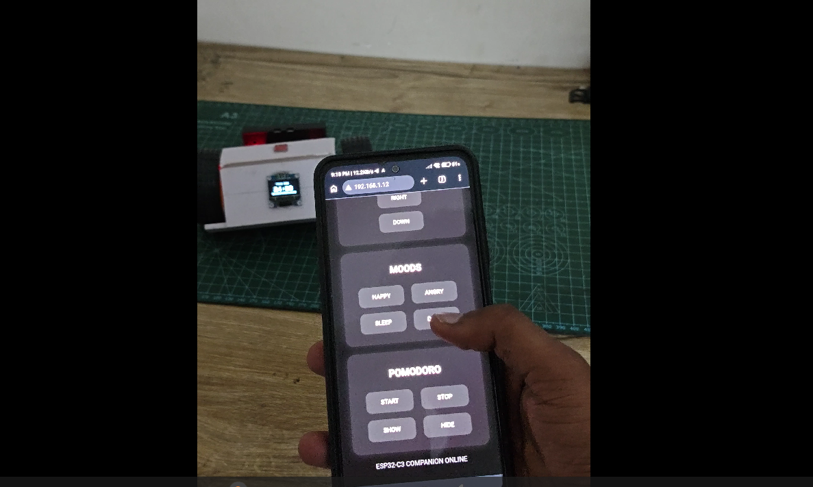
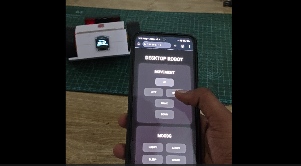
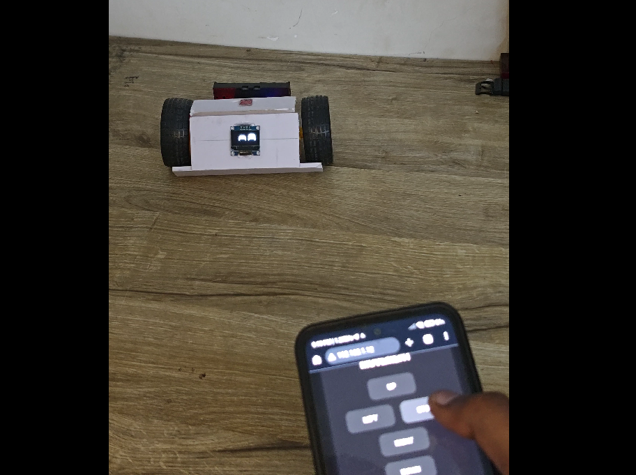
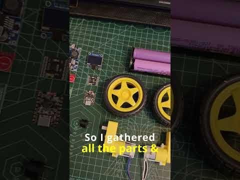
Once the hardware and software were ready, I tested the robot as a complete system.