DIY ESP32 Wifi Self Balancing Robot - B-Robot ESP32 Arduino Programing
by bluino_electronics in Circuits > Arduino
34580 Views, 84 Favorites, 0 Comments
DIY ESP32 Wifi Self Balancing Robot - B-Robot ESP32 Arduino Programing

This article is proudly sponsored by PCBWAY.
PCBWAY make high quality prototyping PCBs for people all over the world. Try it for your self and get 10 PCBs for just $5 at PCBWAY with very great quality, Thanks PCBWAY. The ESP32 Balancing Robot Shield that I developed in this project uses PCBWAY PCB services. In this instructable, I will show you how to build Self Balancing Robot use ESP32 Wifi. Let's get started!
This self balancing robot is based on:
Circuit Diagram

Parts List

- 1 x PCB ESP32 Balancing Robot Shield (https://www.pcbway.com/project/shareproject/ESP32_Balancing_Robot_Shield.html)
- 1 x ESP32 DEVKIT V1 board
- 2 x Stepper Motor Driver A4988
- 1 x 3 axis Acc. and Gyro sensor MPU6050
- 2 x Stepper Motor Nema17
- 1 x Servo Motor MG90S
- 1 x LED 3mm
- 2 x LED 3mm White Super Bright
- 1 x Active BUzzer
- 2 x V-Regulator 5V AMS1117 (SMD)
- 1 x Resistor 1K Ohm
- 1 x Capacitor 0.1uF
- 1 x Capacitor 100uF/16V
- 2 x Capacitor 220uF/16V
- 1 x Rocker Switch Dia. 20mm
- 2 x Rechargeable Battery Li-ion 18650 3,7V
- 1 x Battery Holder 2x 18650
- 1 x Micro USB Cable
- 1 x OTG Adapter
- 1 x Terminal Screw 2 pin 5mm
- 2 x Female Header 15 pin
- 5 x Female Header 8 pin
- 2 x Female Header 4 pin
- 1 x Male Header 2 pin
- 1 x Male Header 3 pin
- 1 x Jumper cap
- 1 x Set screw 5mm
- 1 x Set M3 set screw 10mm
- 2 x O-ring 3mm ID 82mm
- 1 x Set 3D Printed Parts
Order PCB on PCBWAY


To make this project you need to order a prototype PCB on PCBWAY. How to order is very easy and you will get 10 Pcs PCB for $5 with very great PCB quality.
Step to Order:
1. SignUp/Log in on pcbway.com
2. Open this PCB project link ESP32 Wifi Balancing Robot Shield
3. Click Add to cart.
4. Wait moment for PCB review, then Click Check Out.
Solder SMD Component (AMS1117 5V)

This project has two SMD component, it is not too difficult to solder because the size of the SMD component is quite large, so don't worry.
You will need tweezers as a tool to hold the components when soldered.
Place the Components

After finish solder SMD component, next attach other trough hole components on the PCB following the pictures and symbols on the PCB, for details you can follow step by step in the video.
Soldering


Solder all the component legs on the back of the PCB, for details you can follow step by step in the video.
After finish solder, cut all the long legs of the component wire
Attach Modules
.jpg)
.jpg)
Attach the ESP32 board, MPU6050 and two Driver Stepper Motor A4988 into the female header socket as shown, look at the pin name don't get the wrong orientation.
3D Printed Parts
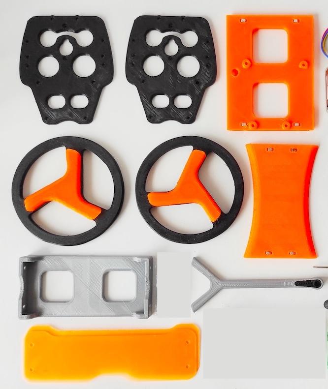
Print all of 3D parts Balancing robot, get design file from thingiverse.com/thing:2306541
List 3D Printed Parts:
- 2x Wheels
- 2x Hub Arm
- 2x Side Panel
- Top Shelf
- Motor Shelf
- Electronics Shelf
- 2x Bumpers
Install 3D Parts
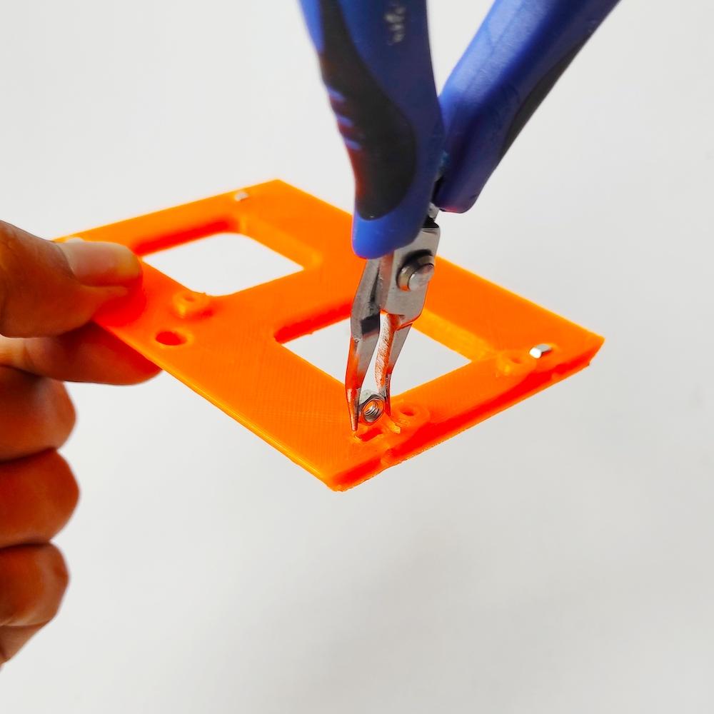
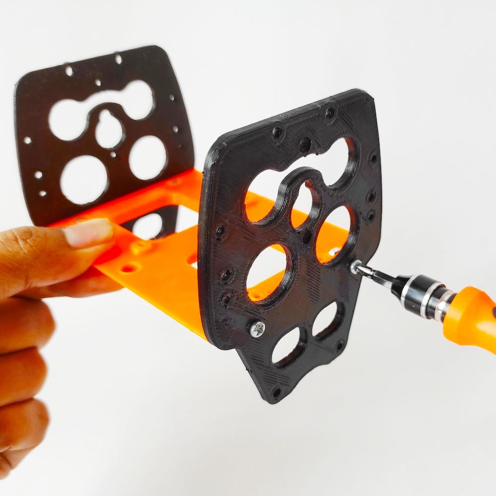
- Insert four M3 nuts into each hole on the edge of the Electronics Shelf (3d printed part).
- Install two Side Panel (3d printed part) on both sides then tie it with a machine screw.
Install Stepper Motor

- Attach two stepper motor Nema17 to the Motor Shelf (3d printed part) then tie it with a machine screw.
Assembly Parts

- Attach Motor Shelf assy with Electronic Shelf Assy then tie it with a machine screw.
Install Electronics Shield
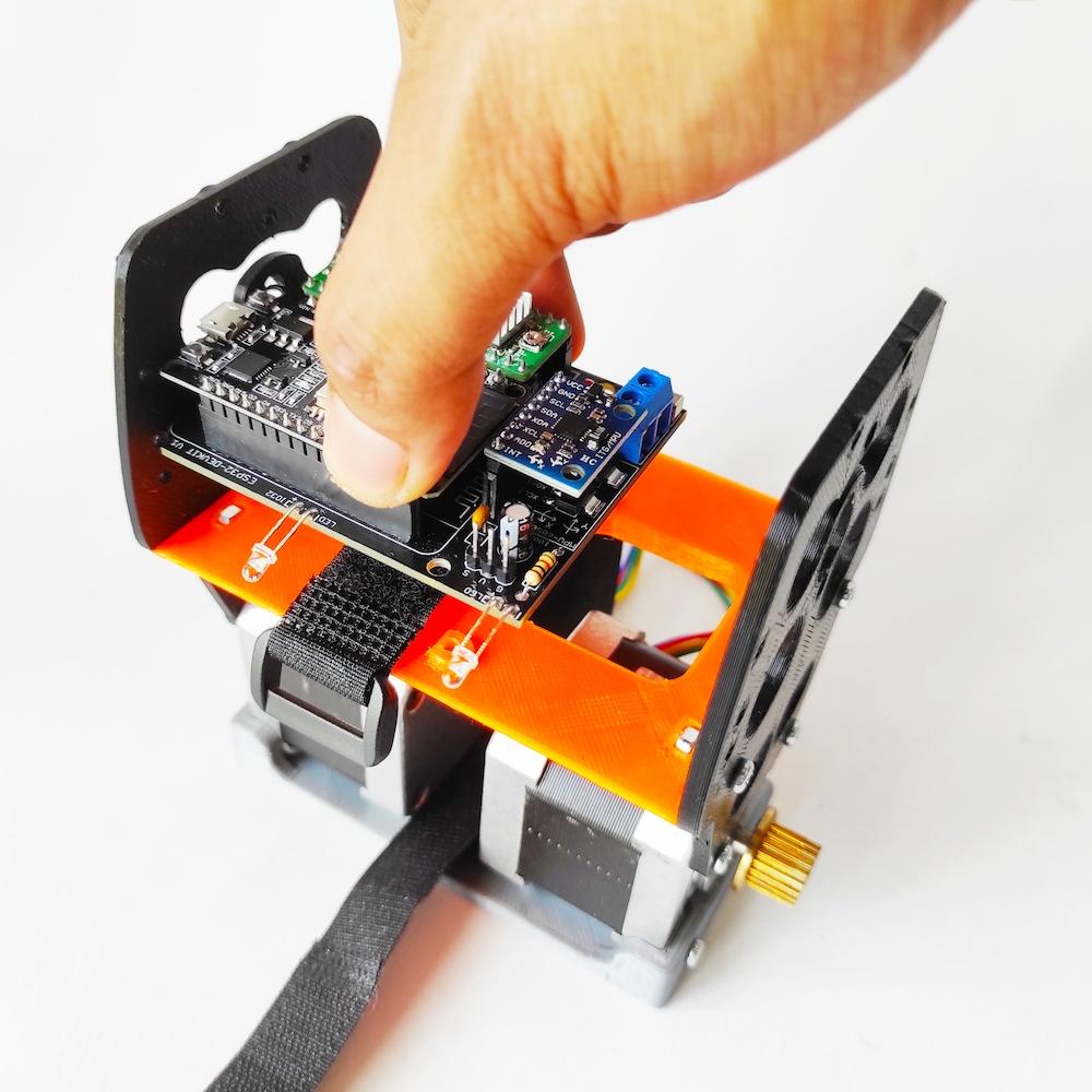
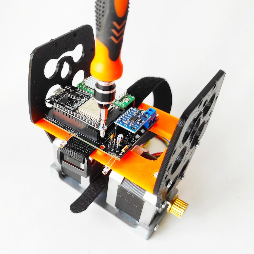
- Put the battery scrap under the electronic shield as shown.
- Attach ESP32 Balancing Robot Shield into Electronic Shelf then tie it with a wood screw.


- Solder dupont jumper cable to rocker switch pin
- Insert the rocker switch into left side hole of Side Panel
- Connect dupont jumper female header to pin on shield as shown
Install Servo Motor

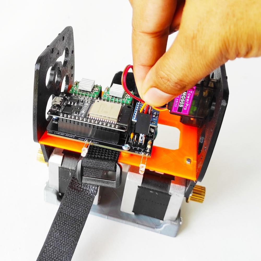
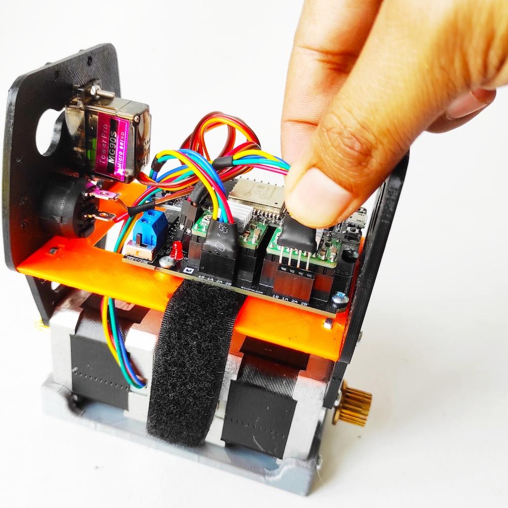
- Insert the motor servo MG90 into left side hole of Side Panel as shown, tie in with M2 machine screw.
- Connect female header servo motor to pin on shield as shown, look at the pin name don't get the wrong orientation.
- Connect two male header of stepper motor to socket on shield as shown.
Install Battery

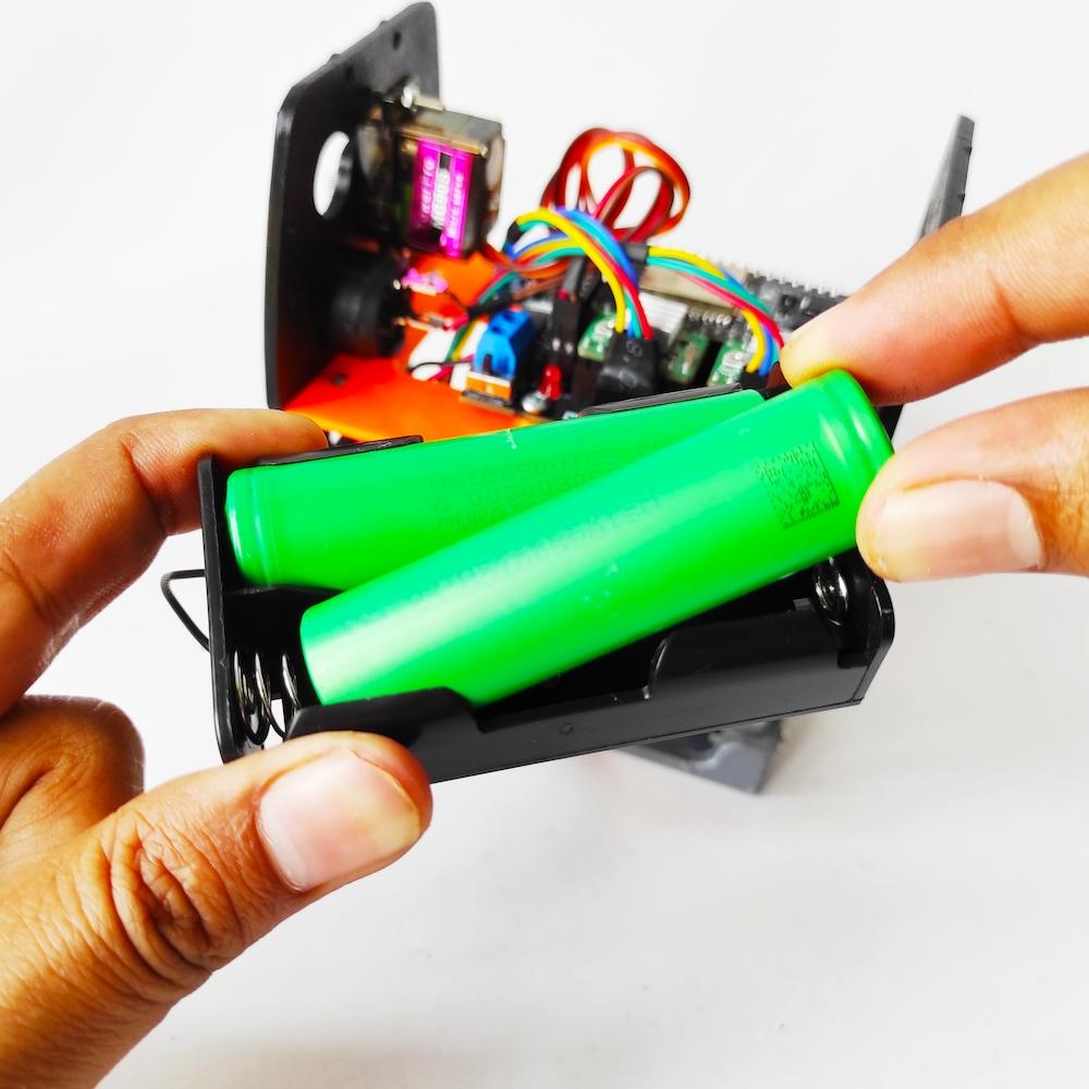
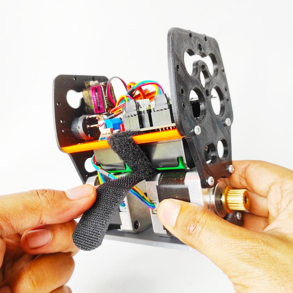
- Connect and screw cable of battery holder into terminal screw on shield, red cable to VM and black cable to GND.
- Attach two batteryto battery holder.
- Insert it below between the Electronic Shelf and the top of the stepper motor then tie it with a scrap battery.
Attach Top Shelf
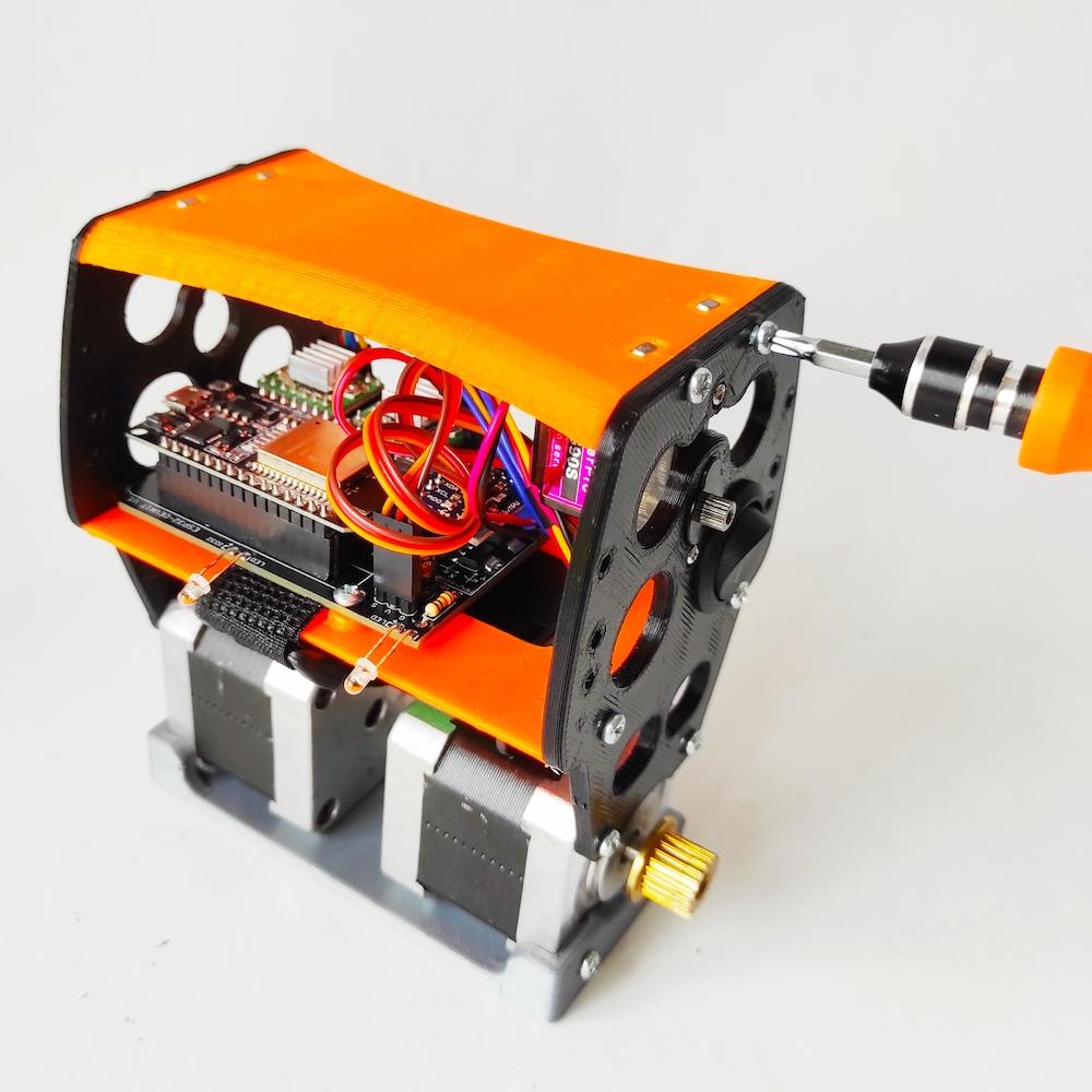
- Insert four M3 nuts into each hole on the edge of the Top Shelf (3d printed part).
- Install on top of Side Panel then tie it with a machine screw.
Install Bumper
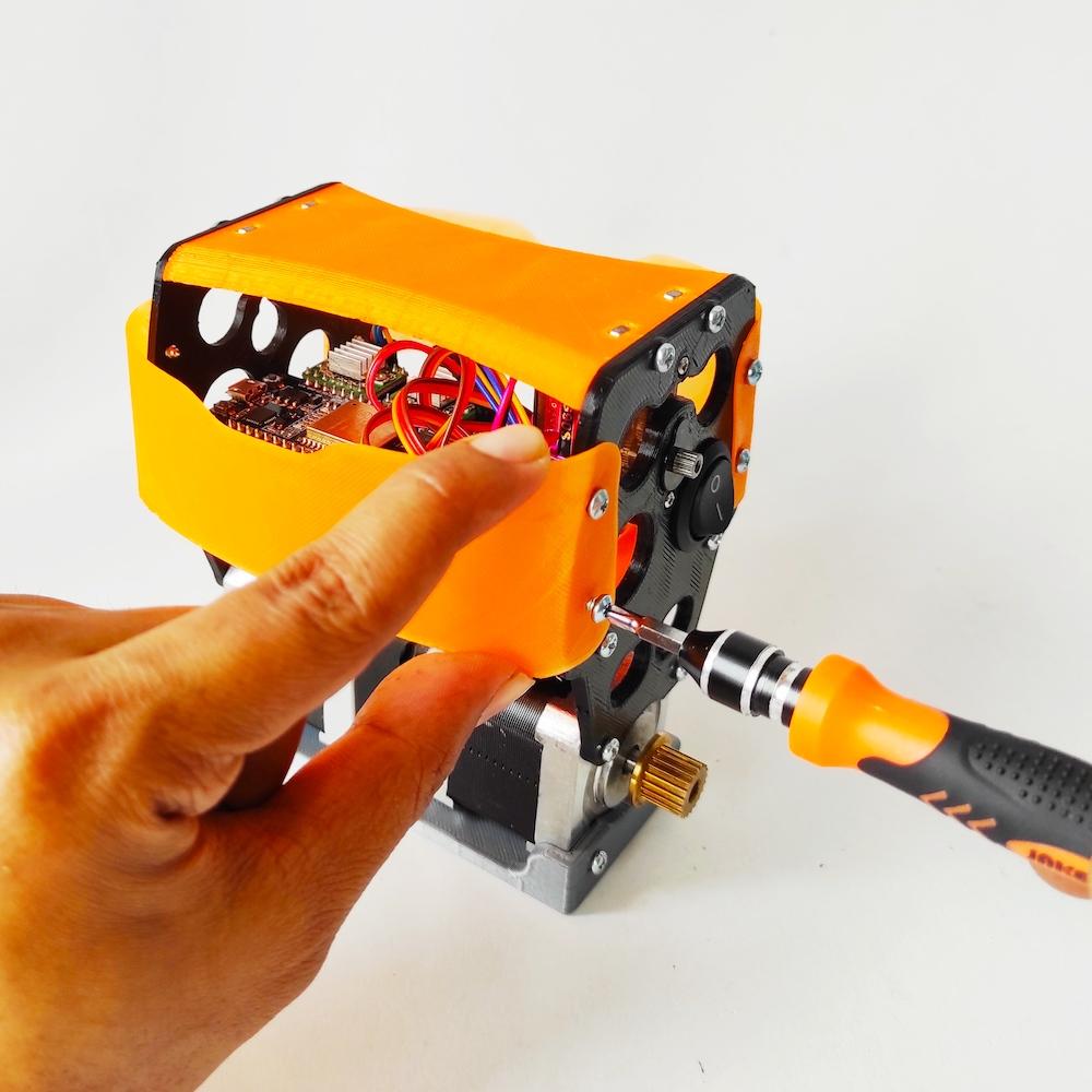
- Install two bumper on the front and back of Side Panel then tie it with a wood screw.
Install Arm
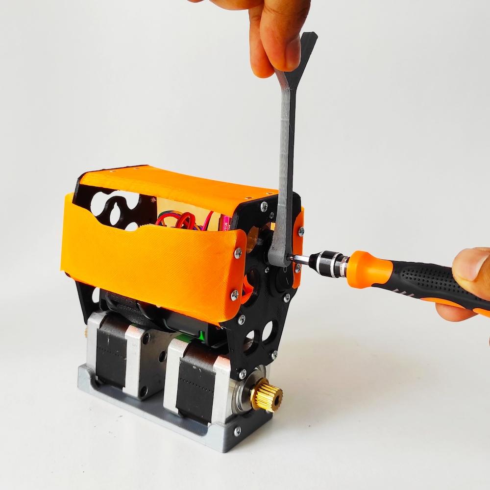
- Turn the servo motor shaft to the center position or half a turn, then attach Addon Arm (3D printed part) into shaft and tie it with screw.
Install Wheels

- Attach Wheel (3D printed part) with HUB (3D printed part)
- Put the O-ring on the edge of the wheel
- Insert whell to shaft of stepper motor
Programming Robot

To make WiFi Self Balancing Robot can controlled by smartphone Android, you have to program ESP32 first. The easy way to program ESP32 that you can use this Android App follow this step:
- Install ESP32 Wifi Balancing Robot from Google Playstore
- Open app, on menu bar select Circuit diagram & Code icon
- Select menu settings, on option Upload Firmware Via select USB OTG, if you want to connect the balancing robot with network of router you can set SSID name & Password.
- Connect ESP32 to your smartphone use USB OTG adapter.
- The last step click icon upload, and wait moment until completed.
-
After finish uploaded program, press reset button.
Otherwise, you can program ESP32 board through a computer using the Arduino IDE software use this sketch download full source code here:
Note: First, your Arduino IDE must be setup to be able use to programming ESP8266 board
/*
 * esp32_wifi_balancing_robot.ino
 *
 *  Created on: 23.02.2021
 *      Author: anonymous
 */

#include <Wire.h>
#include <WiFi.h>
#include <ArduinoOTA.h>
#include <Arduino.h>
#include <AsyncTCP.h>
#include <ESPAsyncWebServer.h>
#include "Control.h"
#include "MPU6050.h"
#include "Motors.h"
#include "defines.h"
#include "globals.h"
#include <stdio.h>
#include "esp_types.h"
#include "soc/timer_group_struct.h"
#include "driver/periph_ctrl.h"
#include "driver/timer.h"
#include "driver/ledc.h"
#include "esp32-hal-ledc.h"

const char* PARAM_FADER1 = "fader1";
const char* PARAM_FADER2 = "fader2";
const char* PARAM_PUSH1 = "push1";
const char* PARAM_PUSH2 = "push2";
const char* PARAM_PUSH3 = "push3";
const char* PARAM_PUSH4 = "push4";
const char* PARAM_TOGGLE1 = "toggle1";
const char* PARAM_FADER3 = "fader3";
const char* PARAM_FADER4 = "fader4";
const char* PARAM_FADER5 = "fader5";
const char* PARAM_FADER6 = "fader6";

/* Wifi Crdentials */
String sta_ssid = "$your_ssid_maximum_32_characters";     // set Wifi network you want to connect to
String sta_password = "$your_pswd_maximum_32_characters";        // set password for Wifi network

unsigned long previousMillis = 0;

AsyncWebServer server(80);

void initMPU6050() {
  MPU6050_setup();
  delay(500);
  MPU6050_calibrate();
}

void initTimers();

void notFound(AsyncWebServerRequest *request) {
  request->send(404, "text/plain", "Not found");
}

void setup() {
  Serial.begin(115200);         // set up seriamonitor at 115200 bps
  Serial.setDebugOutput(true);
  Serial.println();
  Serial.println("*ESP32 Camera Balancing Robot*");
  Serial.println("--------------------------------------------------------");


  pinMode(PIN_ENABLE_MOTORS, OUTPUT);
  digitalWrite(PIN_ENABLE_MOTORS, HIGH);

  pinMode(PIN_MOTOR1_DIR, OUTPUT);
  pinMode(PIN_MOTOR1_STEP, OUTPUT);
  pinMode(PIN_MOTOR2_DIR, OUTPUT);
  pinMode(PIN_MOTOR2_STEP, OUTPUT);
  pinMode(PIN_SERVO, OUTPUT);

  pinMode(PIN_LED, OUTPUT);
  digitalWrite(PIN_LED, LOW);

  pinMode(PIN_WIFI_LED, OUTPUT);
  digitalWrite(PIN_WIFI_LED, LOW);

  pinMode(PIN_BUZZER, OUTPUT);
  digitalWrite(PIN_BUZZER, LOW);

  ledcSetup(6, 50, 16); // channel 6, 50 Hz, 16-bit width
  ledcAttachPin(PIN_SERVO, 6);   // GPIO 22 assigned to channel 1
  delay(50);
  ledcWrite(6, SERVO_AUX_NEUTRO);

  Wire.begin();
  initMPU6050();

  // Set NodeMCU Wifi hostname based on chip mac address
  char chip_id[15];
  snprintf(chip_id, 15, "%04X", (uint16_t)(ESP.getEfuseMac()>>32));
  String hostname = "esp32brobot-" + String(chip_id);

  Serial.println();
  Serial.println("Hostname: "+hostname);

  // first, set NodeMCU as STA mode to connect with a Wifi network
  WiFi.mode(WIFI_STA);
  WiFi.begin(sta_ssid.c_str(), sta_password.c_str());
  Serial.println("");
  Serial.print("Connecting to: ");
  Serial.println(sta_ssid);
  Serial.print("Password: ");
  Serial.println(sta_password);

  // try to connect with Wifi network about 8 seconds
  unsigned long currentMillis = millis();
  previousMillis = currentMillis;
  while (WiFi.status() != WL_CONNECTED && currentMillis - previousMillis <= 8000) {
    delay(500);
    Serial.print(".");
    currentMillis = millis();
  }

  // if failed to connect with Wifi network set NodeMCU as AP mode
  IPAddress myIP;
  if (WiFi.status() == WL_CONNECTED) {
    Serial.println("");
    Serial.println("*WiFi-STA-Mode*");
    Serial.print("IP: ");
    myIP=WiFi.localIP();
    Serial.println(myIP);
    digitalWrite(PIN_WIFI_LED, HIGH);    // Wifi LED on when connected to Wifi as STA mode
    delay(2000);
  } else {
    WiFi.mode(WIFI_AP);
    WiFi.softAP(hostname.c_str());
    myIP = WiFi.softAPIP();
    Serial.println("");
    Serial.println("WiFi failed connected to " + sta_ssid);
    Serial.println("");
    Serial.println("*WiFi-AP-Mode*");
    Serial.print("AP IP address: ");
    Serial.println(myIP);
    digitalWrite(PIN_WIFI_LED, LOW);   // Wifi LED off when status as AP mode
    delay(2000);
  }


  // Send a GET request to <ESP_IP>/?fader=<inputValue>
    server.on("/", HTTP_GET, [] (AsyncWebServerRequest *request) {
    String inputValue;
    String inputMessage;
    OSCnewMessage = 1;

    // Get value for Forward/Backward
    if (request->hasParam(PARAM_FADER1)) {
      OSCpage = 1;
      inputValue = request->getParam(PARAM_FADER1)->value();
      inputMessage = PARAM_FADER1;
      OSCfader[0] = inputValue.toFloat();
    }
    // Get value for Right/Left
    else if (request->hasParam(PARAM_FADER2)) {
      OSCpage = 1;
      inputValue = request->getParam(PARAM_FADER2)->value();
      inputMessage = PARAM_FADER2;
      OSCfader[1] = inputValue.toFloat();
    }
    // Get value for Servo0
    else if (request->hasParam(PARAM_PUSH1)) {
      OSCpage = 1;
      inputValue = request->getParam(PARAM_PUSH1)->value();
      inputMessage = PARAM_PUSH1;
      if(inputValue.equals("1")) OSCpush[0]=1;
      else OSCpush[0]=0;
    }
    // Get value for Setting
    else if (request->hasParam(PARAM_PUSH2)) {
      OSCpage = 2;
      inputValue = request->getParam(PARAM_PUSH2)->value();
      inputMessage = PARAM_PUSH2;
      if(inputValue.equals("1")) OSCpush[2]=1;
      else OSCpush[2]=0;
    }
    // Get value for Buzzer
    else if (request->hasParam(PARAM_PUSH3)) {
      inputValue = request->getParam(PARAM_PUSH3)->value();
      inputMessage = PARAM_PUSH3;
      if(inputValue.equals("1")) {
        digitalWrite(PIN_BUZZER, HIGH);
        delay(150);
        digitalWrite(PIN_BUZZER, LOW);
        delay(80);
        digitalWrite(PIN_BUZZER, HIGH);
        delay(150);
        digitalWrite(PIN_BUZZER, LOW);
        delay(80);
      }
    }
    // Get value for Led
    else if (request->hasParam(PARAM_PUSH4)) {
      inputValue = request->getParam(PARAM_PUSH4)->value();
      inputMessage = PARAM_PUSH4;
      if(inputValue.equals("1")) digitalWrite(PIN_LED, HIGH);
      else digitalWrite(PIN_LED, LOW);
    }
    // Get value for mode PRO
    else if (request->hasParam(PARAM_TOGGLE1)) {
      OSCpage = 1;
      inputValue = request->getParam(PARAM_TOGGLE1)->value();
      inputMessage = PARAM_TOGGLE1;
      if(inputValue.equals("1")) OSCtoggle[0]=1;
      else OSCtoggle[0]=0;
    }
    // Get value for P-Stability
    else if (request->hasParam(PARAM_FADER3)) {
      OSCpage = 2;
      inputValue = request->getParam(PARAM_FADER3)->value();
      inputMessage = PARAM_FADER3;
      OSCfader[0] = inputValue.toFloat();
    }
    // Get value for D-Stability
    else if (request->hasParam(PARAM_FADER4)) {
      OSCpage = 2;
      inputValue = request->getParam(PARAM_FADER4)->value();
      inputMessage = PARAM_FADER4;
      OSCfader[0] = inputValue.toFloat();
    }
    // Get value for P-Speed
    else if (request->hasParam(PARAM_FADER5)) {
      OSCpage = 2;
      inputValue = request->getParam(PARAM_FADER5)->value();
      inputMessage = PARAM_FADER5;
      OSCfader[0] = inputValue.toFloat();
    }
    // Get value for I-Speed
    else if (request->hasParam(PARAM_FADER6)) {
      OSCpage = 2;
      inputValue = request->getParam(PARAM_FADER6)->value();
      inputMessage = PARAM_FADER6;
      OSCfader[0] = inputValue.toFloat();
    }
    else {
      inputValue = "No message sent";
    }
    Serial.println(inputMessage+'='+inputValue);
    request->send(200, "text/text", "");
  });

  server.onNotFound (notFound);    // when a client requests an unknown URI (i.e. something other than "/"), call function "handleNotFound"
  server.begin();                           // actually start the server

  initTimers();

  // default neutral values
  OSCfader[0] = 0.5;
  OSCfader[1] = 0.5;
  OSCfader[2] = 0.5;
  OSCfader[3] = 0.5;

  digitalWrite(PIN_ENABLE_MOTORS, LOW);
  for (uint8_t k = 0; k < 5; k++) {
    setMotorSpeedM1(5);
    setMotorSpeedM2(5);
    ledcWrite(6, SERVO_AUX_NEUTRO + 250);
    delay(200);
    setMotorSpeedM1(-5);
    setMotorSpeedM2(-5);
    ledcWrite(6, SERVO_AUX_NEUTRO - 250);
    delay(200);
  }
  ledcWrite(6, SERVO_AUX_NEUTRO);

  ArduinoOTA.begin();   // enable to receive update/upload firmware via Wifi OTA
}

void loop() {
  ArduinoOTA.handle();

  if (OSCnewMessage) {
    OSCnewMessage = 0;
    processOSCMsg();
  }

  timer_value = micros();

  if (MPU6050_newData()) {

    MPU6050_read_3axis();

    dt = (timer_value - timer_old) * 0.000001; // dt in seconds
    //Serial.println(timer_value - timer_old);
    timer_old = timer_value;

    angle_adjusted_Old = angle_adjusted;
    // Get new orientation angle from IMU (MPU6050)
    float MPU_sensor_angle = MPU6050_getAngle(dt);
    angle_adjusted = MPU_sensor_angle + angle_offset;
    if ((MPU_sensor_angle > -15) && (MPU_sensor_angle < 15))
      angle_adjusted_filtered = angle_adjusted_filtered * 0.99 + MPU_sensor_angle * 0.01;


    // We calculate the estimated robot speed:
    // Estimated_Speed = angular_velocity_of_stepper_motors(combined) - angular_velocity_of_robot(angle measured by IMU)
    actual_robot_speed = (speed_M1 + speed_M2) / 2; // Positive: forward

    int16_t angular_velocity = (angle_adjusted - angle_adjusted_Old) * 25.0; // 25 is an empirical extracted factor to adjust for real units
    int16_t estimated_speed = -actual_robot_speed + angular_velocity;
    estimated_speed_filtered = estimated_speed_filtered * 0.9 + (float) estimated_speed * 0.1; // low pass filter on estimated speed


    if (positionControlMode) {
      // POSITION CONTROL. INPUT: Target steps for each motor. Output: motors speed
      motor1_control = positionPDControl(steps1, target_steps1, Kp_position, Kd_position, speed_M1);
      motor2_control = positionPDControl(steps2, target_steps2, Kp_position, Kd_position, speed_M2);

      // Convert from motor position control to throttle / steering commands
      throttle = (motor1_control + motor2_control) / 2;
      throttle = constrain(throttle, -190, 190);
      steering = motor2_control - motor1_control;
      steering = constrain(steering, -50, 50);
    }

    // ROBOT SPEED CONTROL: This is a PI controller.
    //    input:user throttle(robot speed), variable: estimated robot speed, output: target robot angle to get the desired speed
    target_angle = speedPIControl(dt, estimated_speed_filtered, throttle, Kp_thr, Ki_thr);
    target_angle = constrain(target_angle, -max_target_angle, max_target_angle); // limited output

    // Stability control (100Hz loop): This is a PD controller.
    //    input: robot target angle(from SPEED CONTROL), variable: robot angle, output: Motor speed
    //    We integrate the output (sumatory), so the output is really the motor acceleration, not motor speed.
    control_output += stabilityPDControl(dt, angle_adjusted, target_angle, Kp, Kd);
    control_output = constrain(control_output, -MAX_CONTROL_OUTPUT,  MAX_CONTROL_OUTPUT); // Limit max output from control

    // The steering part from the user is injected directly to the output
    motor1 = control_output + steering;
    motor2 = control_output - steering;

    // Limit max speed (control output)
    motor1 = constrain(motor1, -MAX_CONTROL_OUTPUT, MAX_CONTROL_OUTPUT);
    motor2 = constrain(motor2, -MAX_CONTROL_OUTPUT, MAX_CONTROL_OUTPUT);

    int angle_ready;
    if (OSCpush[0])     // If we press the SERVO button we start to move
      angle_ready = 82;
    else
      angle_ready = 74;  // Default angle
    if ((angle_adjusted < angle_ready) && (angle_adjusted > -angle_ready)) // Is robot ready (upright?)
        {
      // NORMAL MODE
      digitalWrite(PIN_ENABLE_MOTORS, LOW);  // Motors enable
      // NOW we send the commands to the motors
      setMotorSpeedM1(motor1);
      setMotorSpeedM2(motor2);
    } else   // Robot not ready (flat), angle > angle_ready => ROBOT OFF
    {
      digitalWrite(PIN_ENABLE_MOTORS, HIGH);  // Disable motors
      setMotorSpeedM1(0);
      setMotorSpeedM2(0);
      PID_errorSum = 0;  // Reset PID I term
      Kp = KP_RAISEUP;   // CONTROL GAINS FOR RAISE UP
      Kd = KD_RAISEUP;
      Kp_thr = KP_THROTTLE_RAISEUP;
      Ki_thr = KI_THROTTLE_RAISEUP;
      // RESET steps
      steps1 = 0;
      steps2 = 0;
      positionControlMode = false;
      OSCmove_mode = false;
      throttle = 0;
      steering = 0;
    }

    // Push1 Move servo arm
    if (OSCpush[0]) {
      if (angle_adjusted > -40)
        ledcWrite(6, SERVO_MAX_PULSEWIDTH);
      else
        ledcWrite(6, SERVO_MIN_PULSEWIDTH);
    } else
      ledcWrite(6, SERVO_AUX_NEUTRO);

    // Servo2
    //ledcWrite(6, SERVO2_NEUTRO + (OSCfader[2] - 0.5) * SERVO2_RANGE);

    // Normal condition?
    if ((angle_adjusted < 56) && (angle_adjusted > -56)) {
      Kp = Kp_user;            // Default user control gains
      Kd = Kd_user;
      Kp_thr = Kp_thr_user;
      Ki_thr = Ki_thr_user;
    } else // We are in the raise up procedure => we use special control parameters
    {
      Kp = KP_RAISEUP;         // CONTROL GAINS FOR RAISE UP
      Kd = KD_RAISEUP;
      Kp_thr = KP_THROTTLE_RAISEUP;
      Ki_thr = KI_THROTTLE_RAISEUP;
    }

  } // End of new IMU data

}


void processOSCMsg() {
  if (OSCpage == 1) {
    if (modifing_control_parameters)  // We came from the settings screen
    {
      OSCfader[0] = 0.5; // default neutral values
      OSCfader[1] = 0.5; // default neutral values
      OSCtoggle[0] = 0;  // Normal mode
      mode = 0;
      modifing_control_parameters = false;
    }

    if (OSCmove_mode) {
      Serial.print("M ");
      Serial.print(OSCmove_speed);
      Serial.print(" ");
      Serial.print(OSCmove_steps1);
      Serial.print(",");
      Serial.println(OSCmove_steps2);
      positionControlMode = true;
      OSCmove_mode = false;
      target_steps1 = steps1 + OSCmove_steps1;
      target_steps2 = steps2 + OSCmove_steps2;
    } else {
      positionControlMode = false;
      throttle = (OSCfader[0] - 0.5) * max_throttle;
      // We add some exponential on steering to smooth the center band
      steering = OSCfader[1] - 0.5;
      if (steering > 0)
        steering = (steering * steering + 0.5 * steering) * max_steering;
      else
        steering = (-steering * steering + 0.5 * steering) * max_steering;
    }

    if ((mode == 0) && (OSCtoggle[0])) {
      // Change to PRO mode
      max_throttle = MAX_THROTTLE_PRO;
      max_steering = MAX_STEERING_PRO;
      max_target_angle = MAX_TARGET_ANGLE_PRO;
      mode = 1;
    }
    if ((mode == 1) && (OSCtoggle[0] == 0)) {
      // Change to NORMAL mode
      max_throttle = MAX_THROTTLE;
      max_steering = MAX_STEERING;
      max_target_angle = MAX_TARGET_ANGLE;
      mode = 0;
    }
  } else if (OSCpage == 2) { // OSC page 2
    if (!modifing_control_parameters) {
      for (uint8_t i = 0; i < 4; i++)
        OSCfader[i] = 0.5;
      OSCtoggle[0] = 0;

      modifing_control_parameters = true;
      //OSC_MsgSend("$P2", 4);
    }
    // User could adjust KP, KD, KP_THROTTLE and KI_THROTTLE (fadder3,4,5,6)
    // Now we need to adjust all the parameters all the times because we dont know what parameter has been moved
    Kp_user = KP * 2 * OSCfader[0];
    Kd_user = KD * 2 * OSCfader[1];
    Kp_thr_user = KP_THROTTLE * 2 * OSCfader[2];
    Ki_thr_user = KI_THROTTLE * 2 * OSCfader[3];
    // Send a special telemetry message with the new parameters
    char auxS[50];
    sprintf(auxS, "$tP,%d,%d,%d,%d", int(Kp_user * 1000), int(Kd_user * 1000), int(Kp_thr_user * 1000), int(Ki_thr_user * 1000));
    //OSC_MsgSend(auxS, 50);


    // Calibration mode??
    if (OSCpush[2] == 1) {
      Serial.print("Calibration MODE ");
      angle_offset = angle_adjusted_filtered;
      Serial.println(angle_offset);
    }

    // Kill robot => Sleep
    while (OSCtoggle[0] == 1) {
      //Reset external parameters
      PID_errorSum = 0;
      timer_old = millis();
      setMotorSpeedM1(0);
      setMotorSpeedM2(0);
      digitalWrite(PIN_ENABLE_MOTORS, HIGH);  // Disable motors
    }
  }
}
Balancing Robot Is Ready
.jpg)


Let's Play

The WiFi Balancing Robot can be controlled via the Android app in two ways, controlled directly from android to ESP32 (AP mode), connect android to SSID of ESP32 then set IP address on app 192.168.4.1.
Other way is ESP32 (STA mode), android is connected to the same router network then set the IP address on app according to the IP address that is owned by ESP32(i.e. 192.168.0.2).